wiring ISUZU TROOPER 1995 Workshop Manual
[x] Cancel search | Manufacturer: ISUZU, Model Year: 1995, Model line: TROOPER, Model: ISUZU TROOPER 1995Pages: 1928
Page 31 of 1928
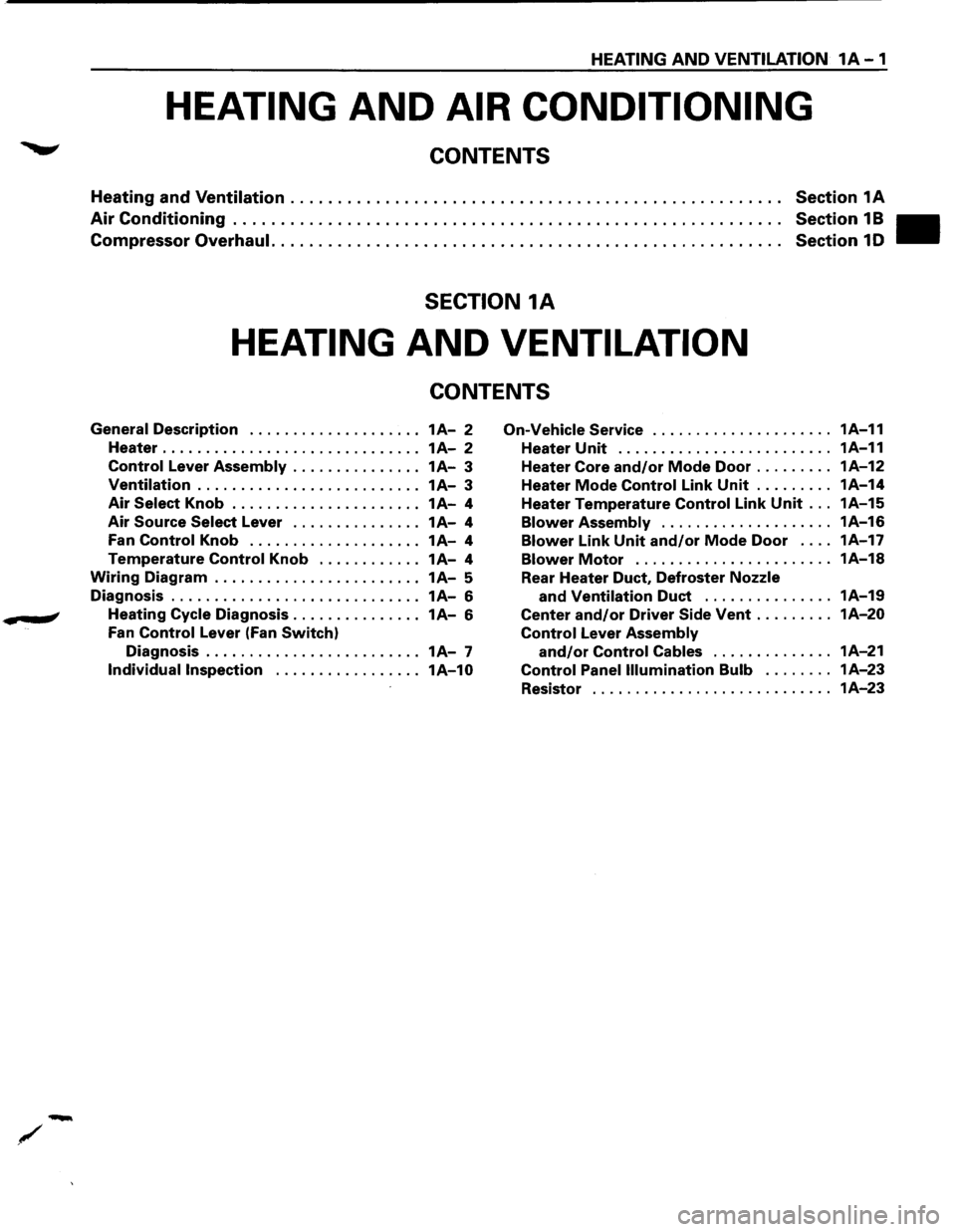
HEATING AND VENTILATION 1A-1
HEATING AND AIR CONDITIONING
CONTENTS
Heating and Ventilation .................................................... Section 1A
Air Conditioning . . . . . . . . . . . . . . . . . . . . . . . . . . . . . . . . . . . . . . . . . . . . . . . . . . . . . . . . . . Section 1 B
Compressor Overhaul. . .
. . . . . . . . . . . . . . . . . . . . . . . . . . . . . . . . . . . . . . . . . . . . . . . . . . . Section 1 D
SECTION 1A
HEATING AND VENTILATION
CONTENTS
General Description .................... 1A-2 On-Vehicle Service ..................... 1A-11
Heater . . . . . . . . . . . . . . . . . . . . . . . . . . . . . . 1
A-2 Heater Unit . . . . . . . . . . . . . . . . . . . . . . . . . 1A-11
Control Lever Assembly . . . . . . . . . . . . . . . 1 A-3 Heater Core and/or Mode Door ......... 1A-12
Ventilation .......................... 1A-3 Heater Mode Control Link Unit ......... 1A-14
Air Select Knob . . . . . . . . . . . . . . . . . . . . . . 1 A-4 Heater Temperature Control Link Unit ... 1A-15
Air Source Select Lever ............... 1A-4 Blower Assembly .................... 1A-16
Fan Control Knob .................... 1A-4 Blower Link Unit and/or Mode Door . . . . 1A-17
Temperature Control Knob ............ 1A-4 Blower Motor ....................... 1A-18
Wiring Diagram . . . . . . . . . . . . . . . . . . . . . . . . 1A-5
Rear Heater Duct, Defroster Nozzle
Diagnosis ............................. 1A-6 and Ventilation Duct ............... 1A-19
.. # Heating Cycle Diagnosis ............... 1A-6 Center and/or Driver Side Vent ......... 1A-20
Fan Control Lever (Fan Switch) Control Lever Assembly
Diagnosis . . . . . . . . . . . . . . . . . . . . . . . . . 1 A-7 and/or Control Cables .............. 1A-21
Individual Inspection ................. 1A-10 Control Panel Illumination Bulb ........ 1A-23
Resistor ............................ 1A-23
Page 35 of 1928
~~[II] BODY ENG. FRAME
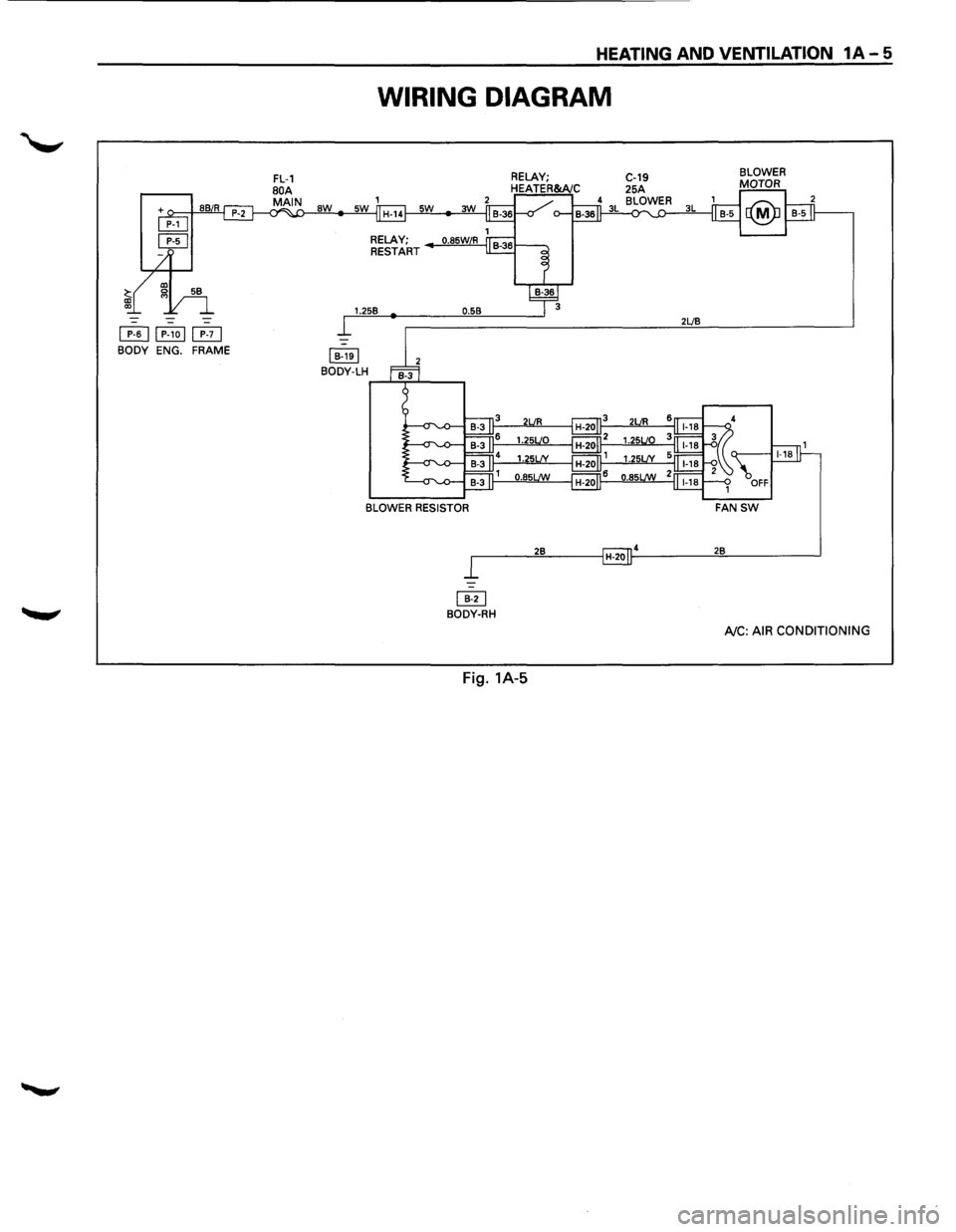
HEATING AND VENTILATION 1A-5
WIRING DIAGRAM
aw
RELAY;
RESTART
1.258
I 8-1el BODY-LH
0.58 2LJ8
BLOWER RESISTOR
r------'2::.::8:,__ __ _,H-201~4 ____ __,2""8 _____ __,
~ BODY-RH
AJC: AIR CONDITIONING
Fig. 1A-5
Page 55 of 1928
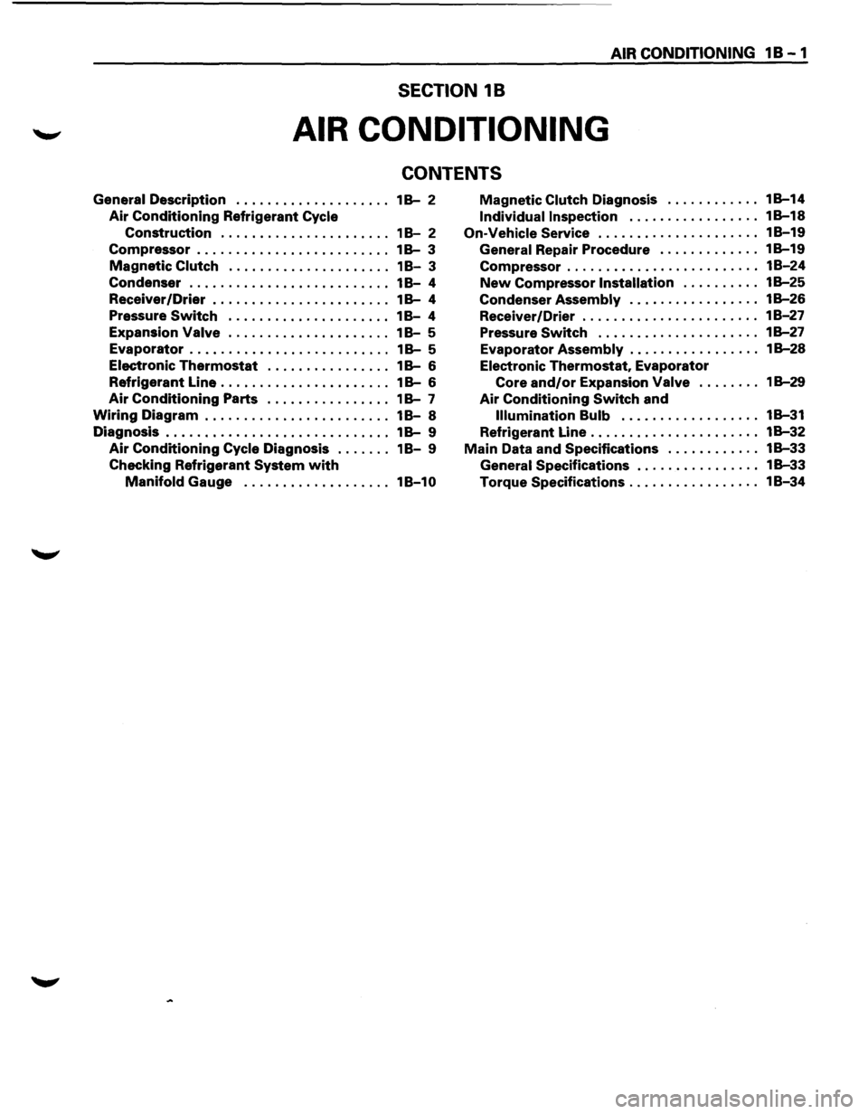
AIR CONDITIONING 1 B - 1
SECTION 18
AIR CONDITIONING
CONTENTS
General Description . . . . . . . . . . . . . . . . . . . . 1 B-2
Air Conditioning Refrigerant Cycle
Construction . . . . . . . . . . . . . . . . . . . . . . 1 8-2
Compressor . . . . . . . . . . . . . . . . . . . . . . . . . 1
B-3
Magnetic Clutch . . . . . . . . . . . . . . . . . . . . . 1 8-3
Condenser . . . . . . . . . . . . . . . . . . . . . . . . . . 1
8-4
Receiver
/Drier . . . . . . . . . . . . . . . . . . . . . . . 1 B-4
Pressure
Switch . . . . . . . . . . . . . . . . . . . . . 1 8-4
Expansion
Valve . .
. . . . . . . . . . . . . . . . . . .
18-5
Evaporator . . . . . . . . . . . . . . . . . . . . . . . . . . 1 B-5
Electronic Thermostat . . . . . . . . . . . . . . . . 1 B-6
Refrigerant Line . . . . . . . . . . . . . . . . . . . . . . 1
B-6
Air Conditioning Parts . . . . . . . . . . . . . . . . 1 B-7
Wiring Diagram . . . . . . . . . . . . . . . . . . . . . . . . 18-8
Diagnosis . . . . . . . . . . . . . . . . . . . . . . . . . . . . . 1
B-9
Air Conditioning Cycle Diagnosis . . . . . . . 18-9
Checking Refrigerant
System with
Manifold Gauge ................... 18-10
Magnetic Clutch Diagnosis ............ 18-14
Individual Inspection ................. 18-18
On-Vehicle Service ..................... 18-19
General Repair Procedure ............. 18-19
Compressor . . . . . . . . . . . . . . . . . . . . . . . . . 18-24
New Compressor Installation . . . . . . . . . . 1 B-25
Condenser Assembly . . . . . . . . . . . . . . . . . 1 B-26
Receiver/Drier ....................... 18-27
Pressure Switch ..................... 18-27
Evaporator Assembly . . . . . . . . . . . . . . . . . 1 B-28
Electronic Thermostat, Evaporator
Core
and/or Expansion Valve ........ 18-29
Air Conditioning Switch and
Illumination Bulb . . . . . . . . . . . . . . . . . . 1 B-31
Refrigerant Line ...................... 18-32
Main Data and Specifications ............ 18-33
General Specifications . . . . . . . . . . . . . . . . 18-33
Torque Specifications ................. 18-34
Page 62 of 1928
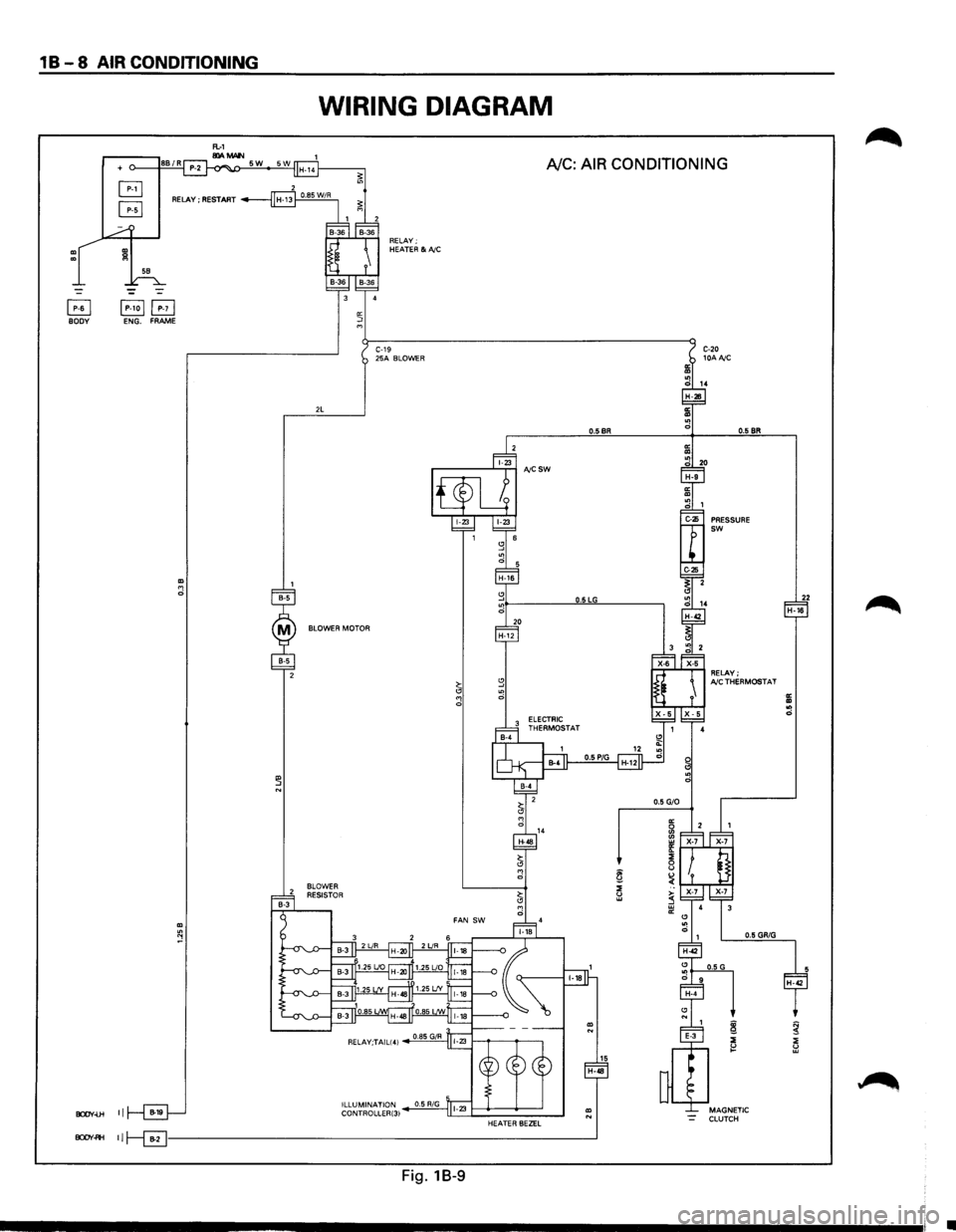
1 B - 8 AIR CONDITIONING
+
RELAY; RESTART
~ ~B BOOV ENG. FRAME
BOOV-Ui II
WIRING DIAGRAM
RELAY; HEATER &NC
A/C: AIR CONDITIONING
BOOV~ 11~--------------------------------------------------------------_j
Fig. 18-9
•
Page 217 of 1928
SUPPLEMENTAL RESTRAINT SYSTEM (SRS) STEERING WHEEL & COLUMN 3F4-7
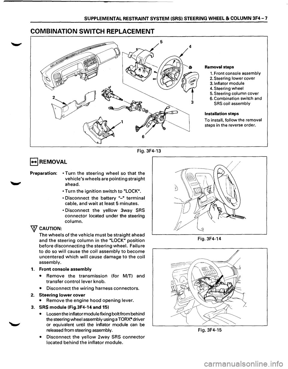
COMBINATION SWITCH REPLACEMENT
Fig. 3F4-13
E) REMOVAL
Preparation: • Turn the steering wheel so that the
vehicle's wheels are pointing straight
ahead.
W CAUTION: •
Turn the ignition switch to "LOCK".
•
Disconnect the battery "-" terminal
cable, and wait at least 5 minutes.
• Disconnect the yellow 3way SRS
connector located under the steering
column.
The wheels ofthe vehicle must be straight ahead
and
the steering column in the "LOCK" position
before disconnecting the steering wheel. Failure
to do so will cause the coil assembly to become
uncentered
which will cause damage to the coil
assembly.
1.
Front console assembly
•
Remove the transmission (for M{f) and
transfer control lever knob.
• Disconnect the wiring harness connectors.
2. Steering lower cover
• Remove the engine hood opening lever.
3. SRS module (Fig.3F4-14 and 15)
• Loosen the inflator module fixing bolt from behind
the steering
wheel assembly using a TORxe driver
or
equivalent until the inflator module can be
released from steering assembly.
•
Disconnect the yellow 2way SRS connector
located behind the inflator module.
3
Removal steps
1. Front console assembly
2. Steering lower cover
3.1nflator module
4. Steering wheel
5. Steering column cover
6. Combination switch and
SRS coil assembly
Installation steps
To install, follow the removal
steps in the reverse order.
Fig. 3F4-14
Fig. 3F4-15
Page 218 of 1928
3F4-8 SUPPLEMENTAL RESTRAINT SYSTEM (SRS) STEERING WHEEL & COLUMN
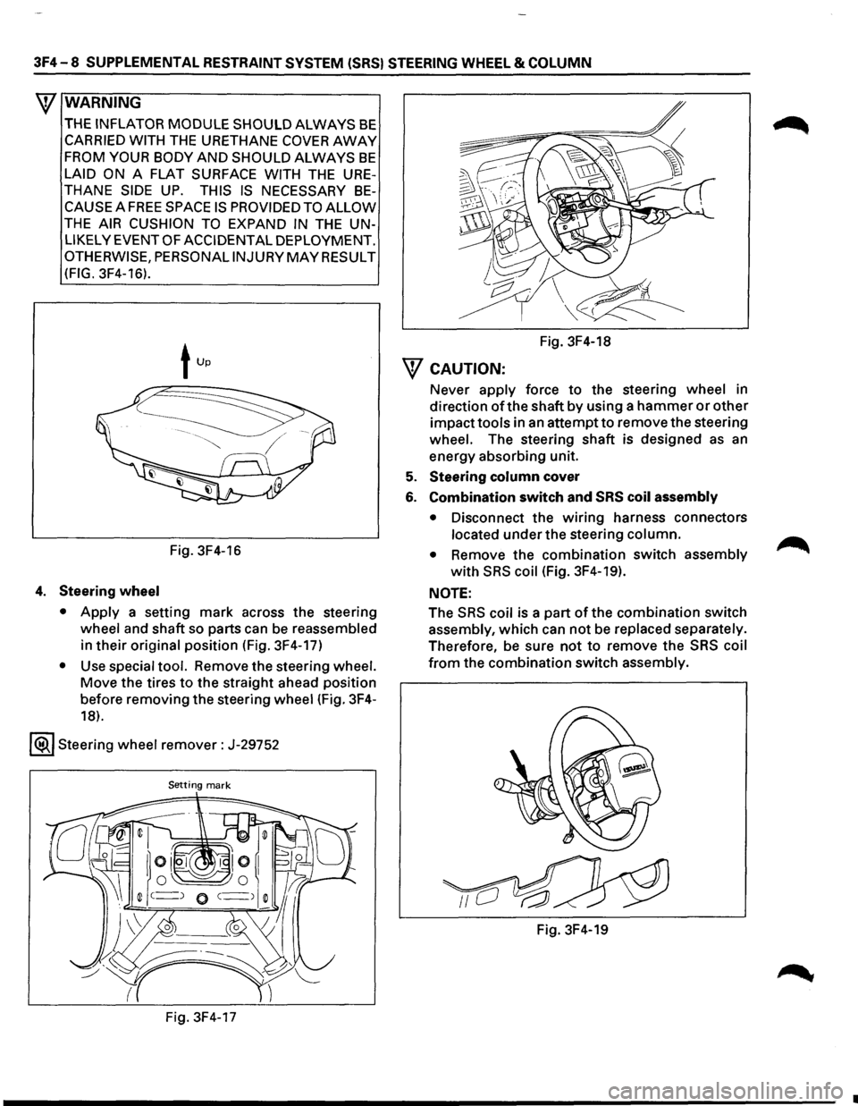
W WARNING
THE INFLATOR MODULE SHOULD ALWAYS BE
CARRIED WITH THE URETHANE COVER AWAY
FROM YOUR BODY AND SHOULD ALWAYS BE
LAID ON A FLAT SURFACE WITH THE URE
THANE SIDE UP. THIS IS NECESSARY BE
CAUSE A FREE SPACE IS PROVIDED TO ALLOW
THE AIR CUSHION TO EXPAND IN THE UN
LIKELY EVENT
OF ACCIDENTAL DEPLOYMENT.
OTHERWISE, PERSONAL INJURY MAY RESULT
(FIG. 3F4-16).
Fig. 3F4-16
4. Steering wheel
•
Apply a setting mark across the steering
wheel and shaft so parts can be reassembled
in
their original position (Fig. 3F4-17)
• Use special tool. Remove the steering wheel.
Move the tires
to the straight ahead position
before removing the steering wheel (Fig.
3F4-
18).
l®..l Steering wheel remover: J-29752
Setting mark
Fig. 3F4-17 Fig.
3F4-18
\V CAUTION:
Never apply force to the steering wheel in
direction
of the shaft by using a hammer or other
impact
tools in an attempt to remove the steering
wheel. The steering shaft is designed as an
energy absorbing unit.
5. Steering column cover
6. Combination switch and SRS coil assembly
•
Disconnect the wiring harness connectors
located under the steering column.
• Remove the combination switch assembly
with SRS coil (Fig. 3F4-19).
NOTE:
The
SRS coil is a part of the combination switch
assembly, which can
not be replaced separately.
Therefore, be sure
not to remove the SRS coil
from the combination switch assembly.
Fig. 3F4-19
•
Page 219 of 1928
SUPPLEMENTAL RESTRAINT SYSTEM (SRS) STEERING WHEEL & COLUMN 3F4-9
B INSTALLATION
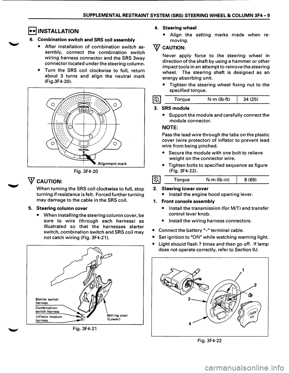
6. Combination switch and SRS coil assembly
•
After installation of combination switch as
sembly, connect the combination switch
wiring harness connector and the SRS 3way
connector located under the steering column.
•
Turn the SRS coil clockwise to full, return
about 3
turns and align the neutral mark
(Fig.3F4-20).
Alignment mark
Fig. 3F4-20
WcAUTION:
When turning the SRS coil clockwise to full, stop
turning if resistance is felt. Forced further turning
may damage to the cable in the SRS coil.
5. Steering column cover
• When installing the steering column cover, be
sure
to wire (through each harness) as
illustrated so that the harnesses starter
switch,
combination switch and SRS coil may
not catch wiring (Fig. 3F4-21 ).
Starter switch
harness
Combination switch harness
Inflator module harness
Fig. 3F4-21
4. Steering wheel
• Align the setting marks made when re
moving.
W CAUTION:
Never apply force to the steering wheel in
direction
of the shaft by using a hammer or other
impact tools in an attempt to remove the steering
wheel. The steering shaft is designed as an
energy absorbing unit.
• Tighten the steering wheel fixing nut to the
specified torque.
Torque
N·m (lb-ft) 34 (25)
3. SRS module
• Support the module and carefully connect the
module connector.
NOTE:
Pass the lead wire through the tabs on the plastic
cover (wire protector) of inflator to prevent lead
wire from being pinched.
• Secure the module with one bolt to relieve
weight on the connector wire.
• Tighten bolts to specified sequence as figure
(Fig. 3F4-22).
Torque
N·m (lb·in) 8 (69)
2. Steering lower cover
• Install the engine hood opening lever.
1. Front console assembly
• Install
the transmission (for MfT) and transfer
control lever knob.
• Install the wiring harness connectors.
• Connect the battery "-"terminal cable.
• Set
ignition to ·oN" while watching warning light.
•
Light should flash 7 times and then go off. If lamp
does not operate correctly, refer to Section 9J.
Fig. 3F4-22
Page 220 of 1928
3F4-10 SUPPLEMENTAL RESTRAINT SYSTEM (SRS) STEERING WHEEL & COLUMN
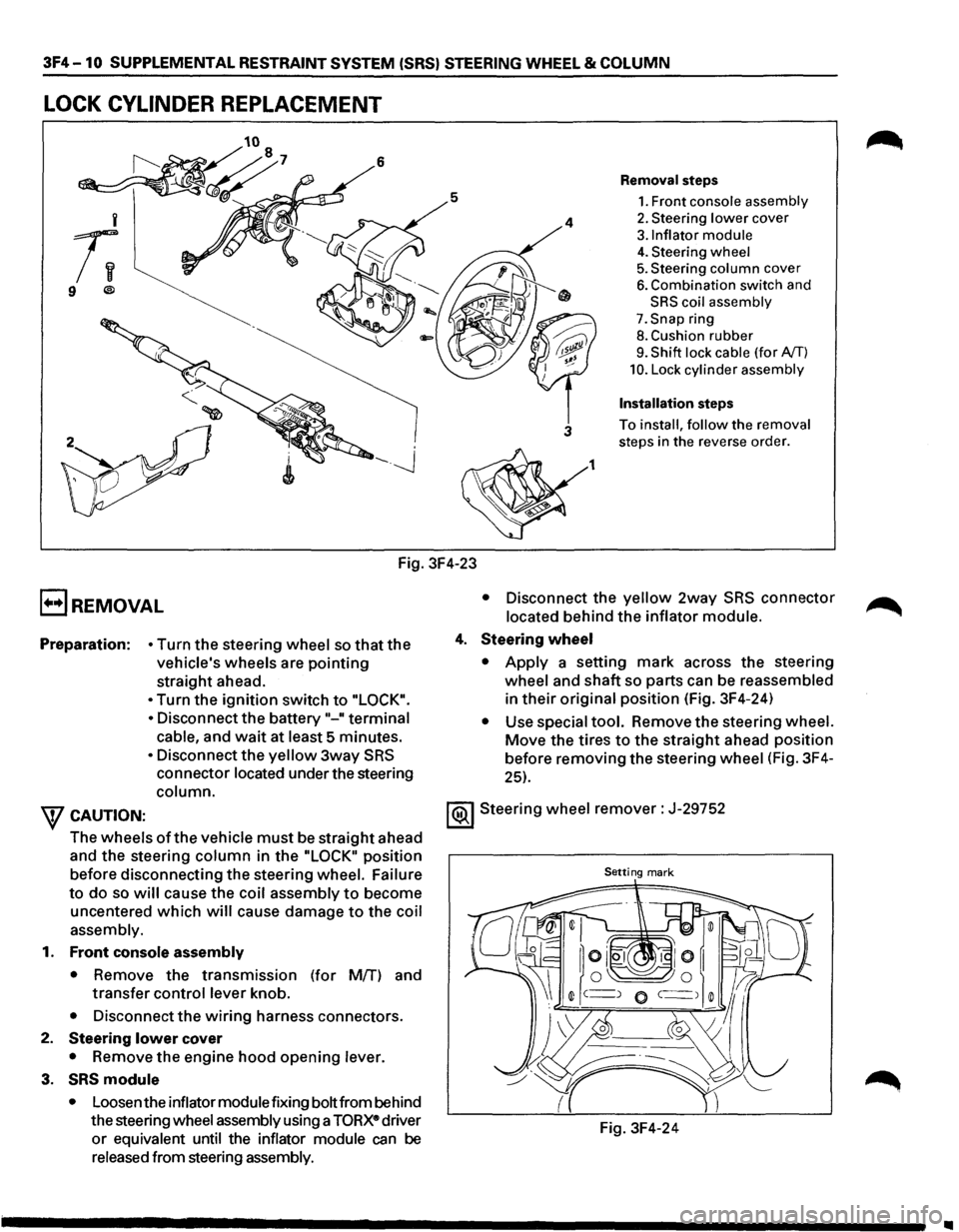
LOCK CYLINDER REPLACEMENT
5
i
;;
9 ®
Fig. 3F4-23
E) REMOVAL
4
3
1
Removal steps
1. Front console assembly
2. Steering lower cover
3.1nflator module
4. Steering wheel
5. Steering column cover
6. Combination switch and
SRS coil assembly
7. Snap ring
8. Cushion rubber
9. Shift lock cable (for AfT)
10. Lock cylinder assembly
Installation steps
To install, follow the removal
steps in the reverse order.
• Disconnect the yellow 2way SRS connector
located behind the inflator module.
Preparation:
• Turn the steering wheel so that the
vehicle's wheels are
pointing
straight ahead.
4. Steering wheel
• Turn the ignition switch to "LOCK".
•
Disconnect the battery"-" terminal
cable, and wait at least 5 minutes.
• Disconnect the yellow 3way SRS
connector located under the steering
column.
• Apply a setting mark across the steering
wheel and
shaft so parts can be reassembled
in
their original position (Fig. 3F4-24)
• Use special tool. Remove the steering wheel.
Move the tires to the straight ahead position
before removing the steering wheel (Fig. 3F4-
25).
W CAUTION: 1®.1 Steering wheel remover: J-29752
The wheels
of the vehicle must be straight ahead
and the steering
column in the "LOCK" position
before disconnecting the steering wheel. Failure
Setting mark
to do so will cause the coil assembly to become
uncentered
which will cause damage to the coil
assembly.
1.
Front console assembly
• Remove the transmission (for Mff) and
transfer
control lever knob.
• Disconnect the wiring harness connectors.
2. Steering lower cover
• Remove the engine hood opening lever.
3. SRS module
• Loosen the inflator module fixing bolt from behind
the steering wheel assembly using a
TORXe driver
or equivalent until the inflator module can be
released from steering assembly. Fig.
3F4-24
•
Page 221 of 1928
SUPPLEMENTAL RESTRAINT SYSTEM (SRS) STEERING WHEEL & COLUMN 3F4-11
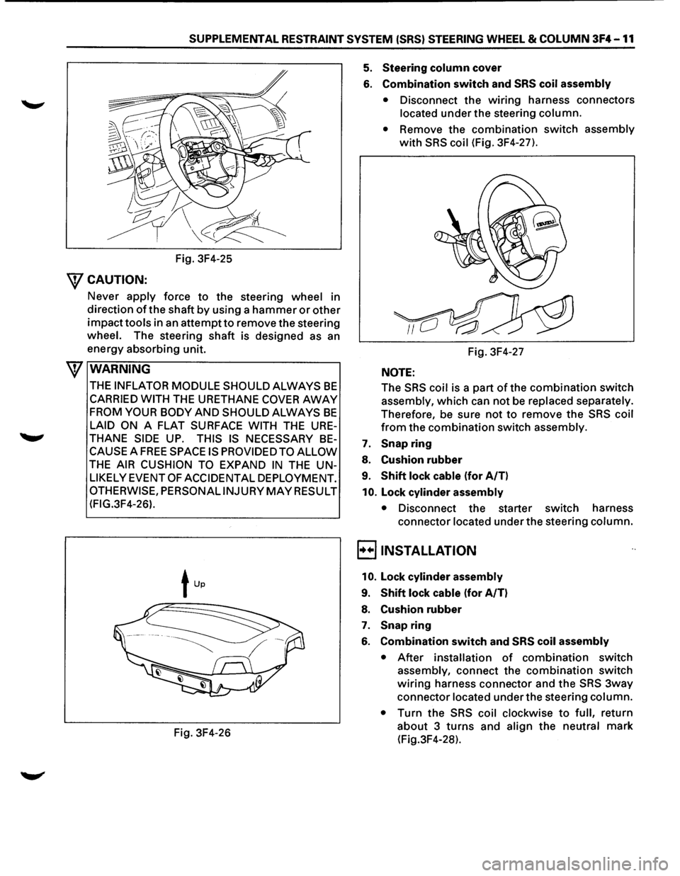
Fig. 3F4-25
WCAUTION:
Never apply force to the steering wheel in
direction
of the shaft by using a hammer or other
impacttools in an attempt to remove the steering
wheel. The steering shaft is designed as an
energy absorbing unit.
\f WARNING
THE INFLATOR MODULE SHOULD ALWAYS BE
CARRIED WITH THE URETHANE COVER AWAY
FROM YOUR BODY AND SHOULD ALWAYS BE
LAID ON A FLAT SURFACE WITH THE URE
THANE SIDE UP. THIS IS NECESSARY BE
CAUSE A FREE SPACE IS PROVIDED TO ALLOW
THE AIR CUSHION TO EXPAND IN THE UN
LIKELY EVENT OF ACCIDENTAL DEPLOYMENT.
OTHERWISE, PERSONALINJURY MAY RESULT
(FIG.3F4-26).
Fig. 3F4-26
5. Steering column cover
6. Combination switch and SRS coil assembly
• Disconnect the wiring harness connectors
located under the steering column.
•
Remove the combination switch assembly
with SRS coil (Fig. 3F4-27).
Fig. 3F4-27
NOTE:
The
SRS coil is a part of the combination switch
assembly, which can not be
replaced separately.
Therefore, be sure not
to remove the SRS coil
from the combination switch assembly.
7. Snapring
8. Cushion rubber
9. Shift lock cable (for A/T)
10. Lock cylinder assembly
• Disconnect the starter switch harness
connector
located under the steering column.
E) INSTALLATION
10. Lock cylinder assembly
9. Shift lock cable (for A/T)
8. Cushion rubber
7. Snap ring
6. Combination switch and SRS coil assembly
• After installation of combination switch
assembly, connect the combination switch
wiring harness connector and the SRS 3way
connector
located under the steering column.
•
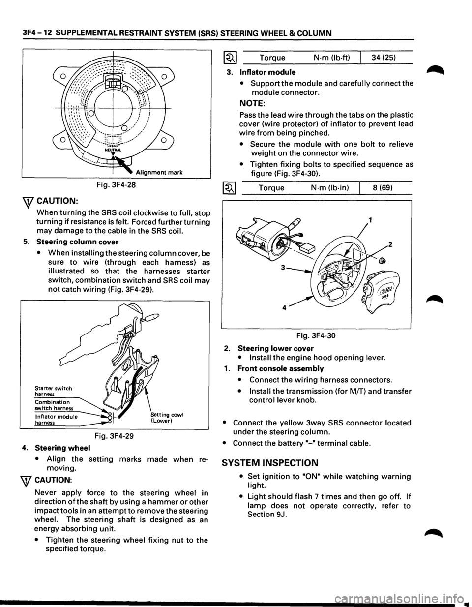
Turn the SRS coil clockwise to full, return
about 3
turns and align the neutral mark
(Fig.3F4-28).
Page 222 of 1928
3F4 -12 SUPPLEMENTAL RESTRAINT SYSTEM (SRS) STEERING WHEEL & COLUMN
Alignment mark
Fig. 3F4-28
\fCAUTION:
When turning the SRS coil clockwise to full, stop
turning if resistance is felt. Forced further turning
may damage to the cable in the SRS coil.
5. Steering column cover
• When installing the steering column cover, be
sure
to wire (through each harness) as
illustrated so that the harnesses starter
switch,
combination switch and SRS coil may
not catch wiring (Fig. 3F4-29).
Starter switch
harness
Combination
switch harness
Inflator module
harness
4. Steering wheel
Fig. 3F4-29
• Align the setting marks made when re
moving.
\fCAUTION:
Never apply force to the steering wheel in
direction
of the shaft by using a hammer or other
impacttools in an attemptto remove the steering
wheel. The steering shaft is designed as an
energy absorbing unit.
• Tighten the steering wheel fixing nut to the
specified torque.
~~~ Torque N·m (lb-ft) 34 (25)
3. Inflator module
• Support the module and carefully connect the
module connector.
NOTE:
Pass the lead wire through the tabs on the plastic
cover (wire protector) of inflator to prevent lead
wire from being pinched.
• Secure the module with one bolt to relieve
weight on the connector wire.
• Tighten fixing bolts to specified sequence as
figure (Fig. 3F4-30).
1~1 Torque N·m (lb-in) 8 (69)
Fig.
3F4-30
2. Steering lower cover
• Install the engine hood opening lever.
1. Front console assembly
• Connect the wiring harness connectors.
• Install the transmission (for Mff) and transfer
control lever knob.
• Connect the yellow 3way SRS connector located
under the steering column.
• Connect the battery"-" terminal cable.
SYSTEM INSPECTION
• Set ignition to "ON" while watching warning
light.
•
Light should flash 7 times and then go off. If
lamp does not operate correctly, refer to
Section 9J.