brake rotor ISUZU TROOPER 1995 Workshop Manual
[x] Cancel search | Manufacturer: ISUZU, Model Year: 1995, Model line: TROOPER, Model: ISUZU TROOPER 1995Pages: 1928
Page 22 of 1928
OB-6 MAINTENANCE AND LUBRICATION
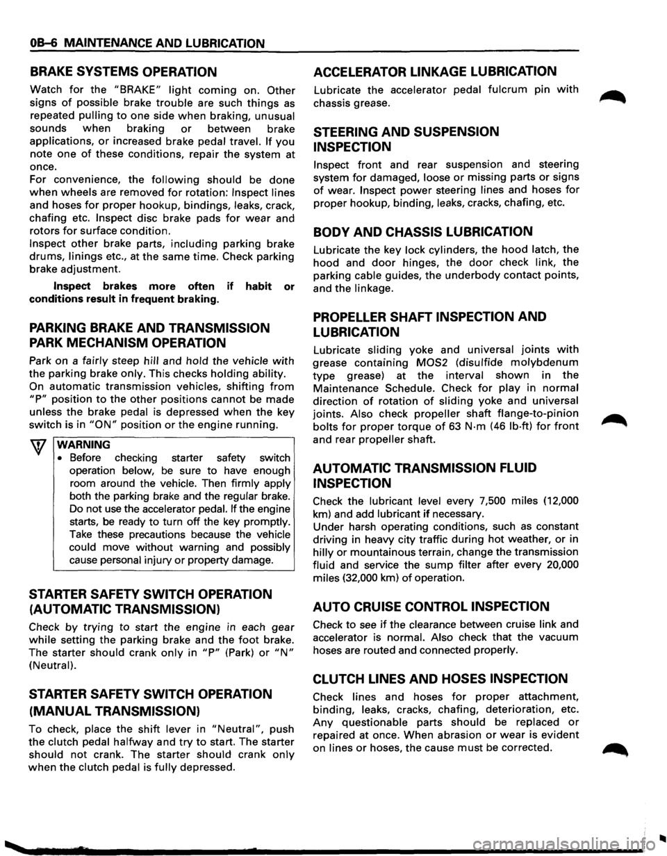
BRAKE SYSTEMS OPERATION
Watch for the "BRAKE" light coming on. Other
signs of possible brake trouble are such things as
repeated pulling to one side when braking, unusual
sounds
when braking or between brake
applications,
or increased brake pedal travel. If you
note one of these conditions, repair the system at
once.
For convenience, the
following should be done
when wheels are removed for rotation: Inspect lines
and hoses
for proper hookup, bindings, leaks, crack,
chafing etc.
Inspect disc brake pads for wear and
rotors
for surface condition.
Inspect other brake parts, including parking brake
drums, linings etc., at the same time. Check parking
brake adjustment.
Inspect brakes more often if habit or
conditions
result in frequent braking.
PARKING BRAKE AND TRANSMISSION
PARK MECHANISM OPERATION
Park on a fairly steep hill and hold the vehicle with
the parking brake only. This checks holding ability.
On
automatic transmission vehicles, shifting from
"P" position to the other positions cannot be made
unless
the brake pedal is depressed when the key
switch is in
"ON" position or the engine running.
WARNING
•
Before checking starter safety switch
operation below,
be sure to have enough
room around the
vehicle. Then firmly apply
both the parking brake and the regular brake.
Do not
use the accelerator pedal. If the engine
starts, be ready
to turn off the key promptly.
Take these precautions because the vehicle
could move
without warning and possibly
cause personal injury
or property damage.
STARTER SAFETY SWITCH OPERATION
(AUTOMATIC TRANSMISSION)
Check by trying to start the engine in each gear
while setting the parking brake and the foot brake.
The starter
should crank only in "P" (Park) or "N"
(Neutral).
STARTER SAFETY SWITCH OPERATION
(MANUAL TRANSMISSION)
To check, place the shift lever in "Neutral", push
the clutch pedal halfway and try to start. The starter
should not crank. The starter should crank only
when the clutch pedal is fully depressed.
ACCELERATOR LINKAGE LUBRICATION
Lubricate the accelerator pedal fulcrum pin with
chassis grease.
STEERING AND SUSPENSION
INSPECTION
Inspect front and rear suspension and steering
system
for damaged, loose or missing parts or signs
of wear. Inspect power steering lines and hoses for
proper hookup, binding, leaks, cracks, chafing, etc.
BODY AND CHASSIS LUBRICATION
Lubricate the key lock cylinders, the hood latch, the
hood and door hinges, the door check link, the
parking cable guides,
the underbody contact points,
and the linkage.
PROPELLER SHAFT INSPECTION AND
LUBRICATION
Lubricate sliding yoke and universal joints with
grease containing MOS2 (disulfide molybdenum
type grease) at the interval shown in the
Maintenance Schedule. Check for play in normal
direction of rotation of sliding yoke and universal
joints. Also check
propeller shaft flange-to-pinion
bolts for proper torque of 63 N·m (46 lb·ft) for front
and rear propeller shaft.
AUTOMATIC TRANSMISSION FLUID
INSPECTION
Check the lubricant level every 7,500 miles (12,000
km) and add lubricant
if necessary.
Under harsh operating conditions, such as constant
driving in heavy city traffic during
hot weather, or in
hilly or mountainous terrain, change the transmission
fluid and service the
sump filter after every 20,000
miles (32,000 km) of operation.
AUTO CRUISE CONTROL INSPECTION
Check to see if the clearance between cruise link and
accelerator is normal. Also check that the vacuum
hoses are routed and connected properly.
CLUTCH LINES AND HOSES INSPECTION
Check lines and hoses for proper attachment,
binding, leaks, cracks, chafing, deterioration, etc.
Any questionable parts should be replaced or
repaired at once. When abrasion or wear is evident
on lines or hoses, the cause must be corrected.
..
Page 321 of 1928
HYDRAULIC BRAKES SA-1
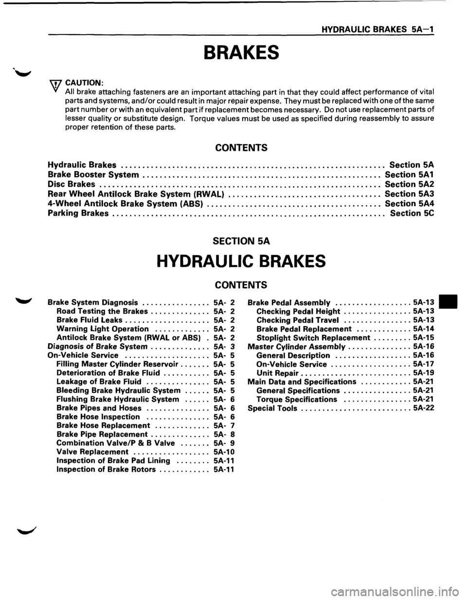
BRAKES
w CAUTION:
• All
brake attaching fasteners are an important attaching part in that they could affect performance of vital
parts and systems, and/or could result in major repair expense. They must be replaced with one of the same
part
number or with an equivalent part if replacement becomes necessary. Do not use replacement parts of
lesser quality or substitute design. Torque values must be used as specified during reassembly to assure
proper retention
of these parts.
CONTENTS
Hydraulic Brakes . . . . . . . . . . . . . . . . . . . . . . . . . . . . . . . . . . . . . . . . . . . . . . . . . . . . . . . . . . . . . . Section SA
Brake Booster System ........................................................ Section 5A1
Disc Brakes . . . . . . . . . . . . . . . . . . . . . . . . . . . . . . . . . . . . . . . . . . . . . . . . . . . . . . . . . . . . . . . . . . Section 5A2
Rear
Wheel Antilock Brake System (RWAL) .................................... Section 5A3
4-Wheel Antilock Brake System (ABS) ......................................... Section 5A4
Parking Brakes . . . . . . . . . . . . . . . . . . . . . . . . . . . . . . . . . . . . . . . . . . . . . . . . . . . . . . . . . . . . . . . .
Section 5C
SECTION 5A
HYDRAULIC BRAKES
CONTENTS
Brake System Diagnosis ................ SA-2
Road
Testing the Brakes . . . . . . . . . . . . . . SA-2
Brake
Fluid Leaks . . . . . . . . . . . . . . . . . . . . SA-2
Warning Light Operation . . . . . . . . . . . . . SA-2
Antilock Brake System (RWAL or ABS) . SA- 2
Diagnosis of Brake System . . . . . . . . . . . . . . SA-3
On-Vehicle Service .................... SA- S
Filling Master Cylinder Reservoir . . . . . . . SA-S
Deterioration of Brake Fluid . . . . . . . . . . . SA-S
Leakage
of Brake Fluid . . . . . . . . . . . . . . . SA-S
Bleeding Brake Hydraulic System . . . . . . SA-S
Flushing Brake Hydraulic System . . . . . . SA-6
Brake Pipes
and Hoses . . . . . . . . . . . . . . . SA-6
Brake Hose
Inspection . . . . . . . . . . . . . . . SA-6
Brake Hose
Replacement . . . . . . . . . . . . . SA-7
Brake Pipe
Replacement . . . . . . . . . . . . . . SA-8
Combination Valve/P & B Valve . . . . . . . SA-9
Valve Replacement . . . . . . . . . . . . . . . . . . SA-1 0
Inspection of Brake Pad Lining . . . . . . . . SA-11
Inspection of Brake Rotors . . . . . . . . . . . . SA-11
Brake Pedal Assembly .................. SA-13 •
Checking Pedal Height ................ SA-13
Checking Pedal Travel ................ SA-13
Brake
Pedal Replacement ............. SA-14
Stoplight Switch Replacement ......... SA-1S
Master Cylinder Assembly ............... SA-16
General Description .................. SA-16
On-Vehicle Service ................... SA-17
Unit Repair .......................... SA-19
Main Data and Specifications ............ SA-21
General Specifications ................ SA-21
Torque Specifications ................ SA-21
Special Tools .......................... SA-22
Page 323 of 1928
HYDRAULIC BRAKES 5A-3
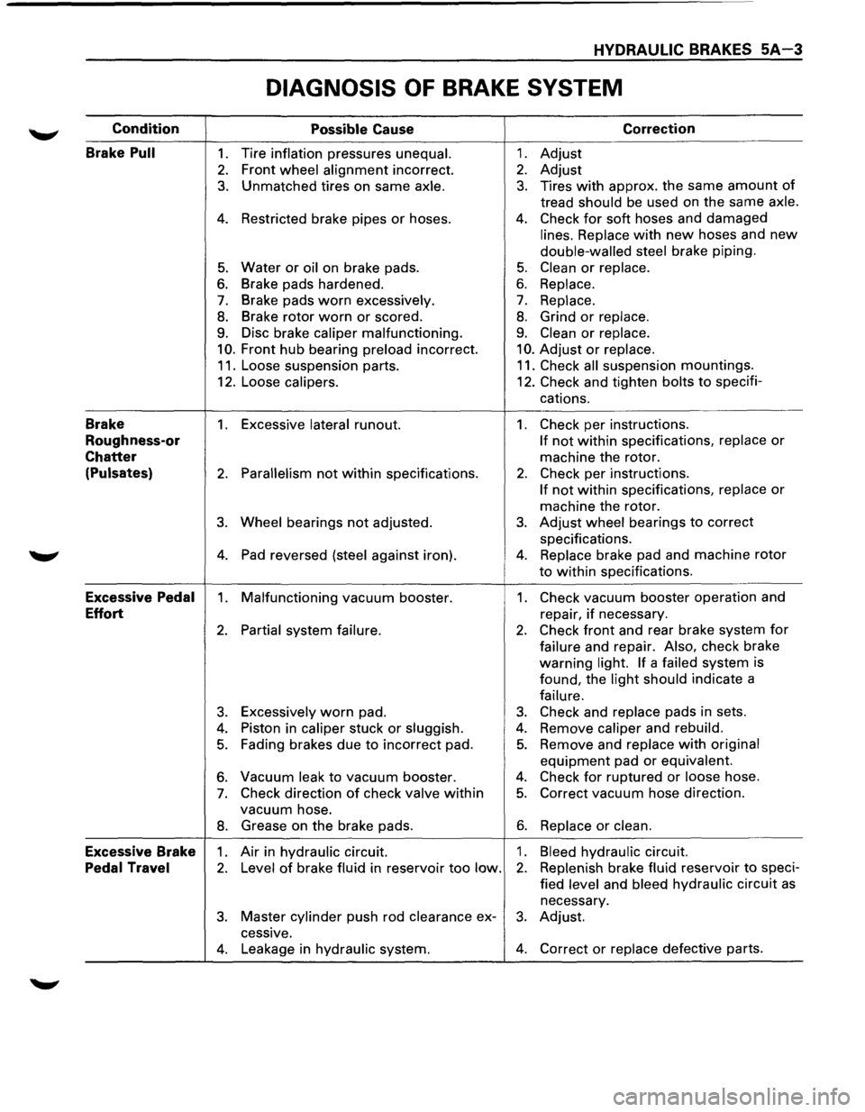
DIAGNOSIS OF BRAKE SYSTEM
Condition
Possible Cause Correction
Brake
Pull 1. Tire inflation pressures unequal. 1. Adjust
2. Front wheel alignment incorrect. 2. Adjust
3. Unmatched tires on same axle. 3. Tires with approx. the same amount of
tread should be used on the same axle.
4. Restricted brake pipes or hoses. 4. Check for soft hoses and damaged
lines. Replace with new hoses and new
double-walled steel brake piping.
5. Water or oil on brake pads. 5. Clean or replace.
6. Brake pads hardened. 6. Replace.
7. Brake pads worn excessively. 7. Replace.
8. Brake rotor worn or scored. 8. Grind or replace.
9. Disc brake caliper malfunctioning. 9. Clean or replace.
10. Front hub bearing preload incorrect. 10. Adjust or replace.
11. Loose suspension parts. 11. Check all suspension mountings.
12. Loose
calipers. 12. Check and tighten bolts to specifi-
cations.
Brake 1. Excessive lateral runout. 1. Check per instructions.
Roughness-or If not within specifications, replace or
Chatter machine the rotor.
(Pulsates) 2. Parallelism not within specifications. 2. Check per instructions.
If not within specifications, replace or
machine the rotor.
3. Wheel bearings not adjusted. 3. Adjust wheel bearings to correct
specifications.
4. Pad reversed (steel against iron). 4. Replace brake pad and machine rotor
to within specifications.
Excessive Pedal 1. Malfunctioning vacuum booster. 1. Check vacuum booster operation and
Effort repair, if necessary.
2. Partial system failure. 2. Check front and rear brake system for
failure and repair. Also, check brake
warning
light. If a failed system
is
found, the
light should indicate a
failure.
3. Excessively worn pad. 3. Check and replace pads in sets.
4. Piston in caliper stuck or sluggish. 4. Remove caliper and rebuild.
5. Fading brakes due to incorrect pad. 5. Remove and replace with original
equipment pad or equivalent.
6. Vacuum leak to vacuum booster. 4. Check for ruptured or loose hose.
7. Check direction of check valve within 5. Correct vacuum hose direction.
vacuum hose.
8. Grease on the brake pads. 6. Replace or clean.
Excessive Brake 1. Air in hydraulic circuit. 1. Bleed hydraulic circuit.
Pedal Travel 2. Level of brake fluid in reservoir too low. 2. Replenish brake fluid reservoir to speci-
fied
level and bleed hydraulic circuit as
necessary.
3. Master cylinder push rod clearance ex-3. Adjust.
cessive.
4. Leakage in hydraulic system. 4. Correct or replace defective parts.
Page 324 of 1928
SA-4 HYDRAULIC BRAKES
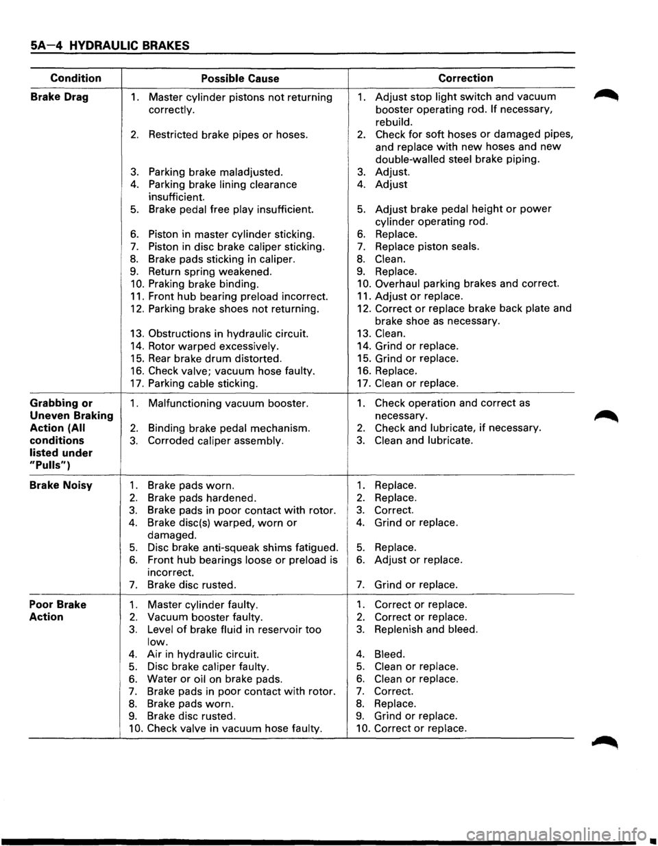
Condition Possible Cause Correction
Brake Drag
1. Master cylinder pistons not returning 1. Adjust stop light switch and vacuum
correctly. booster operating rod. If necessary,
rebuild.
2. Restricted brake pipes or hoses. 2. Check for soft hoses or damaged pipes,
and
replace with new hoses and new
double-walled steel brake piping.
3. Parking brake maladjusted. 3. Adjust.
4. Parking brake lining clearance 4. Adjust
insufficient.
5. Brake pedal free play insufficient. 5. Adjust brake pedal height or power
cylinder operating rod.
6. Piston in master cylinder sticking. 6. Replace.
7. Piston in disc brake caliper sticking. 7. Replace piston seals.
8. Brake pads sticking in caliper. 8. Clean.
9. Return spring weakened. 9. Replace.
10. Praking brake binding. 10. Overhaul parking brakes and correct.
11. Front hub bearing preload incorrect. 11.
Adjust or replace.
12. Parking brake shoes not returning. 12.
Correct or replace brake back plate and
brake shoe
as necessary.
13. Obstructions in hydraulic circuit. 13. Clean.
14. Rotor warped excessively. 14.
Grind or replace.
15. Rear brake drum distorted. 15.
Grind or replace.
16. Check valve; vacuum hose faulty. 16. Replace.
17. Parking cable sticking. 17. Clean or replace.
Grabbing
or 1. Malfunctioning vacuum booster. 1. Check operation and correct as
Uneven Braking necessary.
Action
(All 2. Binding brake pedal mechanism. 2. Check and lubricate, if necessary.
conditions
3. Corroded caliper assembly. 3. Clean and lubricate.
listed
under
"Pulls")
Brake Noisy 1 . Brake pads worn. 1. Replace.
2. Brake pads hardened. 2. Replace.
3. Brake pads in poor contact with rotor. 3. Correct.
4. Brake disc(s) warped, worn or 4. Grind or replace.
damaged.
5. Disc brake anti-squeak shims fatigued. 5. Replace.
6. Front hub bearings loose or preload is 6. Adjust or replace.
incorrect.
7. Brake disc rusted. 7. Grind or replace.
Poor Brake 1. Master cylinder faulty. 1. Correct or replace.
Action 2. Vacuum booster faulty. 2. Correct or replace.
3. Level of brake fluid in reservoir too 3. Replenish and bleed.
low.
4. Air in hydraulic circuit. 4. Bleed.
5. Disc brake caliper faulty. 5. Clean or replace.
6. Water or oil on brake pads. 6. Clean or replace.
7. Brake pads in poor contact with rotor. 7. Correct.
8. Brake pads worn. 8. Replace.
9. Brake disc rusted. 9. Grind or replace.
10. Check valve in vacuum hose faulty. 10. Correct or replace.
•
Page 331 of 1928
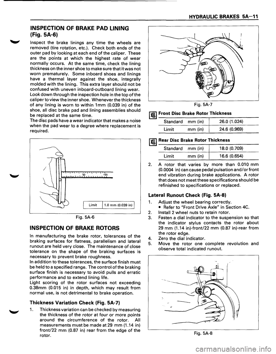
INSPECTION OF BRAKE PAD LINING
(Fig. SA-6)
Inspect the brake linings any time the wheels are
removed (tire rotation, etc.). Check both ends
of the
outer pad by
looking at each end of the caliper. These
are the points at which the highest rate
of wear
normally occurs. At the same time, check the lining
thickness on the inner shoe to make sure that it was not
worn prematurely. Some inboard shoes and linings
have a thermal layer against the shoe, integrally
molded
with the lining. This extra layer should not be
confused with uneven inboard-outboard lining wear.
Look
down through the inspection hole in the top of the
caliper to view the inner shoe. Whenever the thickness
of any lining is worn to within 1 mm (0.039 in) of the
shoe,
all disc brake pad and lining assemblies should
be replaced at the same time.
The disc pads have a
wear indicator that makes a noise
when the pad wear to a degree where replacement is
required.
100
Limit 11.0 mm (0.039 in) I
Fig. 5A-6
INSPECTION OF BRAKE ROTORS
In manufacturing the brake rotor, tolerances of the
braking surfaces
for flatness, parallelism and lateral
runout are held very close. The maintenance of close
tolerance
on the shape of the braking surfaces is
necessary to prevent brake roughness.
In addition to these tolerances, the surface finish must
be held to a specified range. The control ofthe braking
surface finish is necessary to avoid
pulls and erratic
performance and to extend
lining life.
Light scoring of the rotor surfaces not exceeding
0.38mm (0.015 in) in depth, which may result from
normal use, is not detrimental to brake operation.
Thickness Variation Check (Fig. 5A-7)
1. Thickness variation can be checked by measuring
the thickness
of the rotor at four or more points
around the circumference
of the rotor. All
measurements must be made at 29 mm (1.14 in)
front/22 mm (0.87 in) rear from the edge of the
rotor.
HYDRAULIC BRAKES 5A-11
Fig. 5A-7
~~~ Front Disc Brake Rotor Thickness
Standard mm (in) 26.0 (1.024)
Limit mm(in) 24.6 (0.969)
~~~Rear Disc Brake Rotor Thickness
Standard mm (in) 18.0 (0.709)
Limit mm (in) 16.6 (0.654)
2. A rotor that varies by more than 0.010 mm
(0.0004 in) can cause pedal pulsation and/or front
end vibration during brake applications. A rotor
that does not meet these specifications should be
refinished
to specifications or replaced.
Lateral Runout Check (Fig. 5A-8)
1. Adjust the wheel bearing correctly.
• Refer to "Front Drive Axle" in Section 4C.
2. Install 2 wheel nuts to retain rotor.
3. Fasten a dial indicator to the suspension so that
the indicator stylus contacts the rotor about
29 mm (1.14 in)-front/22 mm (0.87 in)-rear from
the rotor edge.
4. Zero the dial indicator.
5. Move the rotor one complete revolution and
observe
total indicated runout.
Fig. 5A-8
Page 332 of 1928
SA-12 HYDRAULIC BRAKES
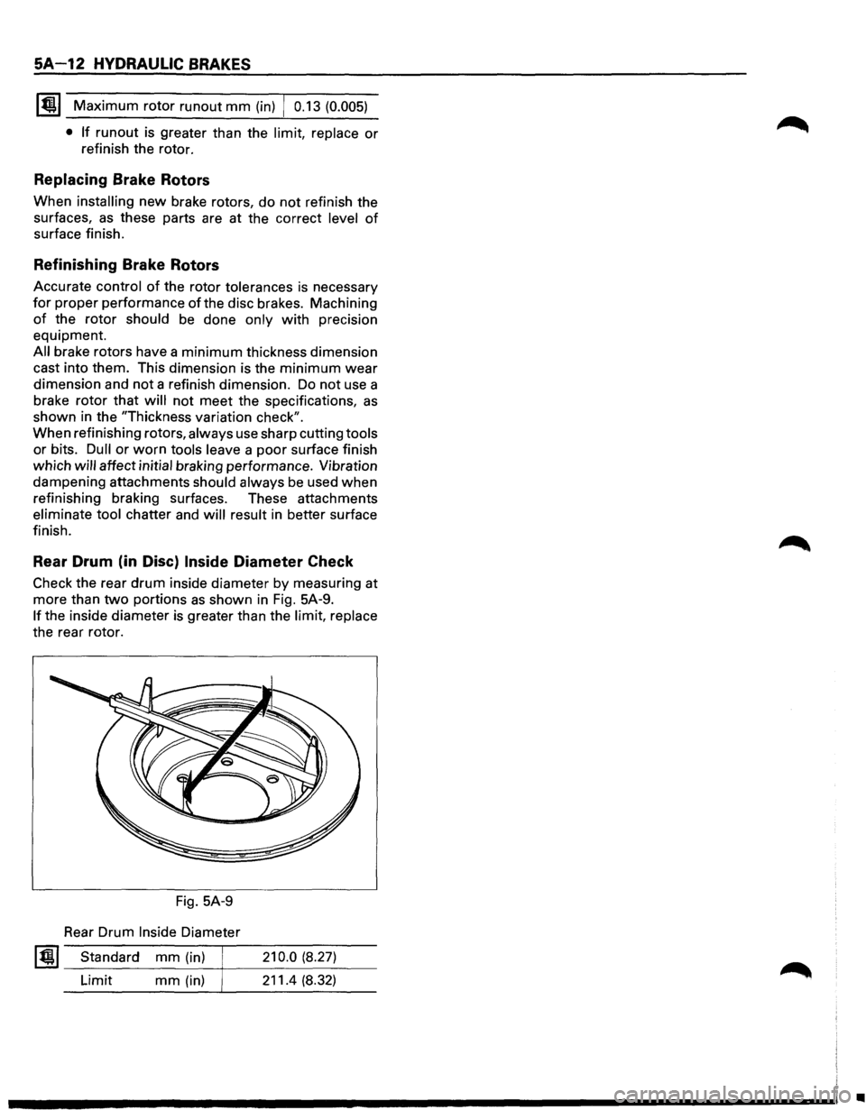
ltilU Maximum rotor runout mm (in) 0.13 (0.005)
• If
runout is greater than the limit, replace or
refinish the rotor.
Replacing Brake Rotors
When installing new brake rotors, do not refinish the
surfaces,
as these parts are at the correct level of
surface finish.
Refinishing Brake Rotors
Accurate control of the rotor tolerances is necessary
for proper performance of the disc brakes. Machining
of the rotor should be done only with precision
equipment.
All brake rotors have a minimum thickness dimension
cast into them. This dimension is the
minimum wear
dimension and
not a refinish dimension. Do not use a
brake rotor
that will not meet the specifications, as
shown in the "Thickness variation check".
When refinishing rotors,
always use sharp cutting tools
or bits. Dull or worn tools leave a poor surface finish
which
will affect initial braking performance. Vibration
dampening attachments
should always be used when
refinishing braking surfaces. These attachments
eliminate tool chatter and will result in better surface
finish.
Rear Drum (in Disc) Inside Diameter Check
Check the rear drum inside diameter by measuring at
more than
two portions as shown in Fig. 5A-9.
If the inside diameter is greater than the limit, replace
the rear rotor.
Fig. 5A-9
Rear Drum
Inside Diameter
ltil!.l Standard mm (in)
Limit
mm (in)
210.0 (8.27)
211.4 (8.32)
•
Page 351 of 1928
DISC BRAKES 5A2-1
SECTION 5A2
DISC BRAKES
w CAUTION:
All brake attaching fasteners are an important attaching part in that they could affect performance of vital
parts and systems, and/or could result in major repair expense. They must be replaced with one of the same
part
number or with an equivalent part if replacement becomes necessary. Do not use replacement parts of
lesser quality or substitute design. Torque values must be used as specified during reassembly to assure
proper retention of these parts.
CONTENTS
General Description . . . . . . . . . . . . . . . . . . . . 5A2-1
Operation . . . . . . . . . . . . . . . . . . . . . . . . . . . . 5A2-1
Diagnosis
..................... See Section SA
On-Vehicle Service . . . . . . . . . . . . . . . . . . . . 5A2-2
Front Disc Brakes . . . . . . . . . . . . . . . . . . . . 5A2-2
Brake Pads
Inspection . .
. . . . . . . . . . . . 5A2-2
Brake Pads Replacement . . . . . . . . . . . 5A2-3
Servicing
the Rotor . . . . . . . . . . . . . . . . 5A2-4
Caliper Replacement . .
. . . . . . . . . . . . . 5A2-6
Rebuilding
the Caliper . . . . . . . . . . . . . 5A2-8 Rear
Disc Brakes .................... 5A2-1 0
Brake
Pads Inspection ............. 5A2-1 0
Brake Pads Replacement ........... 5A2-1 0
Servicing the Rotor ............... 5A2-12
Caliper Replacement .............. 5A2-14
Rebuilding the
Caliper ............. 5A2-17
Parking Brakes . . . . . . . . . . . . . . . .
See Section SC
Main Data and Specifications ........... 5A2-19
General Specifications ............... 5A2-19
Torque Specifications
............... 5A2-19
GENERAL DESCRIPTION
The disc brake assembly consists of a caliper, piston,
rotor, pad assembly and
support bracket. The caliper
assembly has a single bore and is mounted to the
support bracket with 2 mounting bolts. The support
bracket allows the caliper to move laterally against the
rotor. The
caliper is a one-piece casting with the
inboard side containing the piston bore. A square cut
rubber
seal is located in a groove in the piston bore
which provides the hydraulic seal between the piston
and the cylinder
wall.
NOTE:
• Replace all components included in repair kits
used
to service this caliper.
• Lubricate rubber parts with clean brake fluid to
ease assembly.
• If any hydraulic component is removed or
disconnected, it may be necessary to bleed all or
part of the brake system.
• Replace pads in axle sets only.
•
The torque values specified are for dry,
unlubricated fasteners.
• Perform service operation a clean bench free
from all mineral oil materials.
OPERATION
Hydraulic pressure, created by applying the brake
pedal, is converted by the caliper to a stopping force.
This force acts
equally against the piston and the
bottom of the caliper bore to move the piston outward
and to move (slide) the caliper inward resulting in a
clamping action on the rotor. This clamping action
forces the
linings against the rotor, creating friction to
stop the vehicle.
Page 353 of 1928
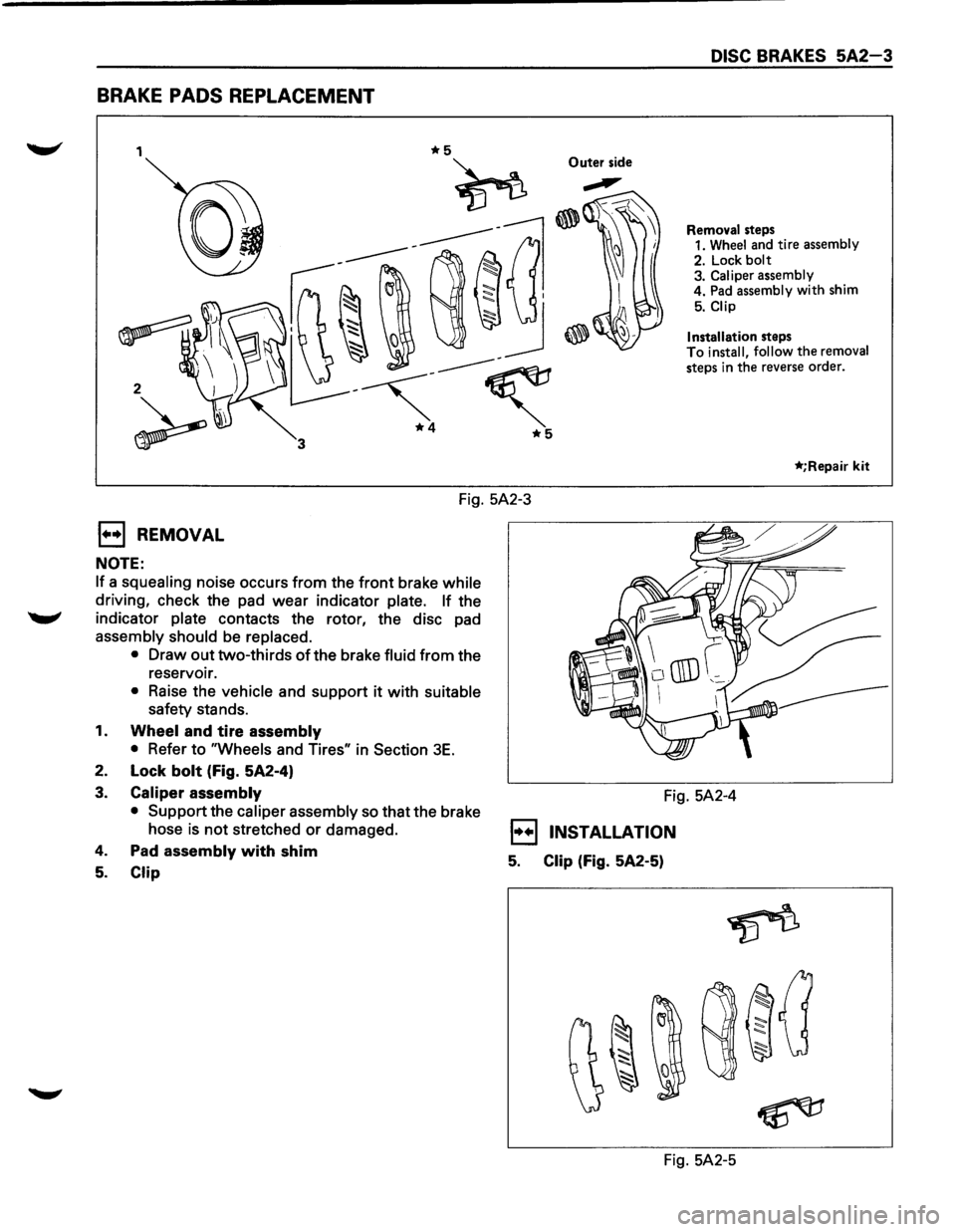
BRAKE PADS REPLACEMENT
1 Outer side
2
DISC BRAKES 5A2-3
Removal steps
1. Wheel and tire assembly
2. Lock
bolt 3. Caliper assembly
4. Pad assembly with shim
5. Clip
Installation
steps To install, follow the removal
steps in the reverse order.
*;Repair kit
Fig. 5A2-3
1••1 REMOVAL
NOTE:
If a squealing noise occurs from the front brake while
driving, check the pad wear indicator plate. If the
........., indicator plate contacts the rotor, the disc pad
assembly should be replaced.
•
Draw out two-thirds of the brake fluid from the
reservoir.
• Raise the vehicle and support it with suitable
safety stands.
1. Wheel and tire assembly
•
Refer to "Wheels and Tires" in Section 3E.
2. Lock bolt (Fig. 5A2-4)
3. Caliper assembly
• Support
the caliper assembly so that the brake
hose
is not stretched or damaged.
4. Pad assembly with shim
5. Clip
Fig. 5A2-4
1••1 INSTALLATION
5. Clip (Fig. 5A2-5)
Fig. 5A2-5
Page 354 of 1928
5A2-4 DISC BRAKES
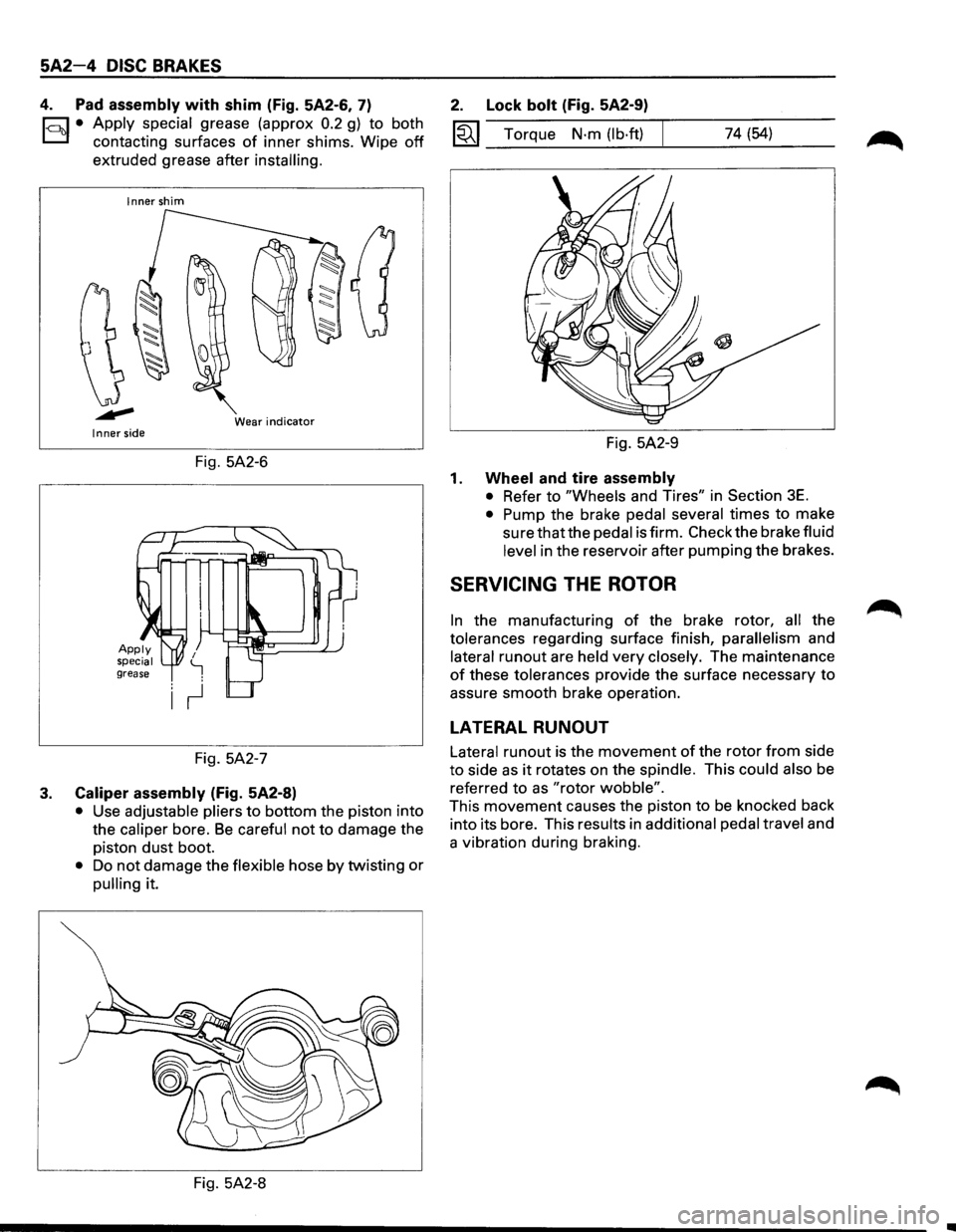
4. Pad assembly with shim (Fig. 5A2-6, 7)
1-c::~t:.l• Apply ~pecial grease (approx 0.2 g) to both
contactmg surfaces
of inner shims. Wipe off
extruded grease after installing.
Inner shim
Wear
indicator Inner side
Fig. 5A2-6
Fig. 5A2-7
3. Caliper assembly (Fig. 5A2-8)
• Use adjustable pliers to bottom the piston into
the
caliper bore. Be careful not to damage the
piston
dust boot.
• Do not damage the flexible hose by twisting or
pulling it.
Fig. 5A2-8
2. Lock bolt (Fig. 5A2-9)
1«1 Torque N·m (lb·ft) 74 (54)
Fig. 5A2-9
1. Wheel and tire assembly
• Refer to "Wheels and Tires" in Section 3E.
• Pump the brake pedal several times to make
sure that the pedal is firm. Check the brake fluid
level in the reservoir after pumping the brakes.
SERVICING THE ROTOR
In the manufacturing of the brake rotor, all the
tolerances regarding surface finish,
parallelism and
lateral
runout are held very closely. The maintenance
of these tolerances provide the surface necessary to
assure smooth brake operation.
LATERAL RUNOUT
Lateral runout is the movement of the rotor from side
to side as it rotates on the spindle. This could also be
referred
to as "rotor wobble".
This movement causes the piston to be knocked back
into its bore. This results in
additional pedal travel and
a vibration during braking.
Page 355 of 1928
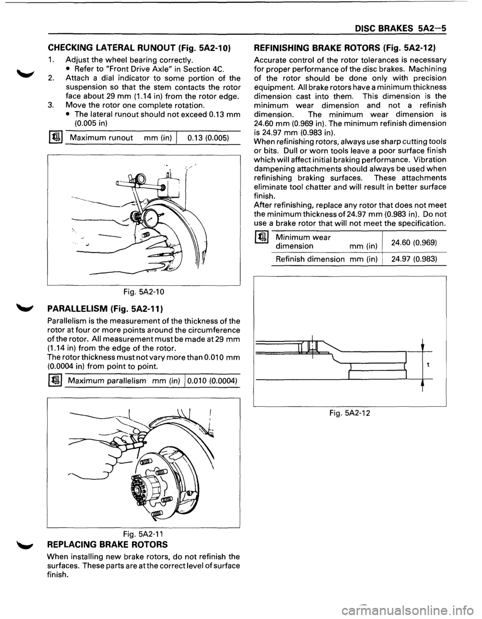
CHECKING LATERAL RUNOUT (Fig. 5A2-10)
1. Adjust the wheel bearing correctly.
•
Refer to "Front Drive Axle" in Section 4C.
2. Attach a dial indicator to some portion of the
suspension so that the stem contacts the
rotor
face about 29 mm (1.14 in) from the rotor edge.
3. Move the rotor one complete rotation.
• The lateral runout should not exceed 0.13 mm
(0.005 in)
~~~ Maximum runout mm (in) I 0.13 (0.005)
Fig. 5A2-1 0
'-' PARALLELISM (Fig. 5A2-11)
Parallelism is the measurement of the thickness of the
rotor at
four or more points around the circumference
of the rotor. All measurement must be made at 29 mm
(1.14 in) from the edge of the rotor.
The
rotor thickness must not vary more than 0.010 mm
(0.0004 in) from point to point.
~~~ Maximum parallelism mm (in) I 0.010 (0.0004)
----------1 '-----...
Fig. 5A2-11
'-' REPLACING BRAKE ROTORS
When installing new brake rotors, do not refinish the
surfaces. These parts are
atthe correct level of surface
finish.
DISC BRAKES 5A2-5
REFINISHING BRAKE ROTORS (Fig. 5A2-12)
Accurate control of the rotor tolerances is necessary
for proper performance ofthe disc brakes. Machining
of the rotor should be done only with precision
equipment.
All brake rotors have a minimum thickness
dimension cast into them. This dimension
is the
minimum wear dimension and not a refinish
dimension. The
minimum wear dimension is
24.60 mm (0.969 in). The minimum refinish dimension
is 24.97
mm (0.983 in).
When refinishing rotors,
always use sharp cutting tools
or bits. Dull or worn tools leave a poor surface finish
which
will affect initial braking performance. Vibration
dampening attachments
should always be used when
refinishing braking surfaces. These attachments
eliminate tool chatter and will result in better surface
finish.
After refinishing, replace any rotor that does not meet
the minimum thickness of 24.97 mm (0.983 in). Do not
use a brake rotor that will not meet the specification.
~~~ Minimum wear
dimension mm (in) 24.60 (0.969)
Refinish dimension
mm (in) 24.97
(0.983)
I
II lllJl I
1 t
I
Fig. 5A2-12