brake rotor ISUZU TROOPER 1995 Owner's Manual
[x] Cancel search | Manufacturer: ISUZU, Model Year: 1995, Model line: TROOPER, Model: ISUZU TROOPER 1995Pages: 1928
Page 495 of 1928
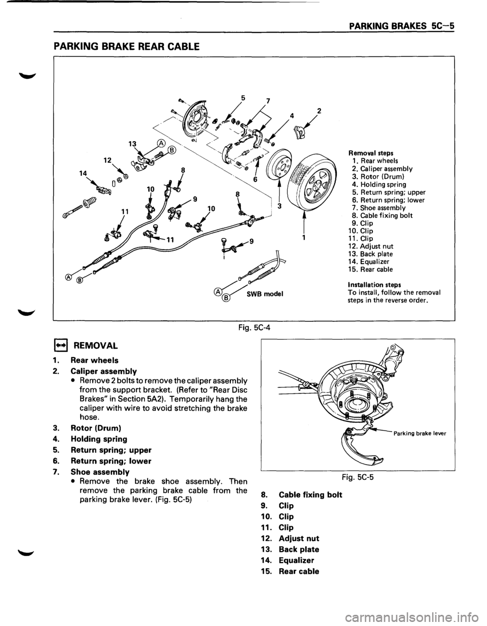
PARKING BRAKE REAR CABLE
1
v9
;#
~SWBmodel
Fig. 5C-4
E) REMOVAL
1. Rear wheels
2. Caliper assembly
• Remove 2 bolts to remove the caliper assembly
from the support bracket. (Refer to "Rear Disc
Brakes" in
Section 5A2). Temporarily hang the
caliper with wire to avoid stretching the brake
hose.
3. Rotor (Drum)
4.
Holding spring
5. Return spring; upper
6. Return spring; lower
7. Shoe assembly
• Remove the brake shoe assembly. Then
remove the parking brake
cable from the
parking brake
lever. (Fig. 5C-5) 8.
9.
10.
11.
12.
13.
14. 15.
Cable fixing bolt
Clip
Clip
Clip
Adjust nut
Back
plate
Equalizer
Rear cable
PARKING BRAKES SC-5
Removal steps
1. Rear wheels
2. Caliper assembly 3. Rotor (Drum)
4. Holding spring 5. Return spring; upper
6. Return spring; lower 7. Shoe assembly 8. Cable fixing bolt 9. Clip 10.Ciip 11. Clip
12. Adjust nut 13. Back plate 14. Equalizer 15. Rear cable
Installation
steps To install, follow the removal steps in the reverse order.
Parking brake lever
Fig. SC-5
Page 496 of 1928
5C-6 PARKING BRAKES
1••1 INSTALLATION
15. Rear cable
hl • Apply grease (BESCO L-2 or equivalent) to the
D connecting portion of the rear cable and
equalizer.
14. Equalizer
13. Back plate
12. Adjust nut
• Tighten the adjust nut to the specified torque.
1~1 Torque N-m (lb-in) I 6 (52)
• To adjust the parking brake, refer to "Parking
Brake Adjustment" in this Section.
11,10, 9. Clip
~~~ Torque N·m (lb·in) I 6 (52)
8. Cable fixing bolt
• Tighten the cable fixing bolt to the specified
torque.
~~~ Torque N·m (lb·in) 6 (52)
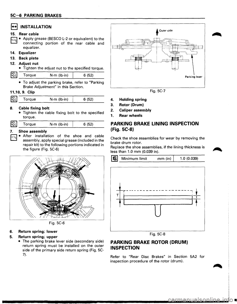
7. Shoe assembly
h1 • After installation of the shoe and cable
D assembly, apply special grease (included in the
repair kit)
to the following portions indicated in
the figure (Fig.
5C-6)
Fig. 5C-6
6. Return spring; lower
5. Return spring; upper
• The parking brake lever side (secondary side)
return spring
must be installed on the outer
side
of the primary side return spring (Fig. 5C-
7).
+Outer side
Fig. 5C-7
4. Holding spring
3. Rotor (Drum)
2. Caliper assembly
1. Rear wheels
Parking lever
PARKING BRAKE LINING INSPECTION
(Fig. SC-8)
Check the shoe assemblies for wear by removing the
brake
drum rotor.
Replace the shoe assemblies, if the lining thickness is
less than 1.0 mm (0.039 in).
1@1 Minimum limit mm (in) J 1.0 (0.039)
-1---r-----------------------,_1_ . '
T I It
u
Fig. 5C-8
PARKING BRAKE ROTOR (DRUM)
INSPECTION
Refer to "Rear Disc Brakes" in Section 5A2 for
inspection procedure
of the rotor (drum).
•
Page 497 of 1928
PARKING BRAKE ADJUSTMENT
1. Adjustment of parking brake assembly
• Prior to lever stroke adjustment, adjust the rear
brake
shoe/rotor (drum) gap. Perform this
procedure
by loosening the adjust nut of the
equalizer.
a) Remove the adjusting hole plug (rubber) and
turn the shoe adjusting screw
downward with a
small screwdriver so that shoes will expand
until
they get into close touch with the rotor.
(Turn
down the adjusting screw notch by notch
until the rotor does not turn.)
b) Turn the adjusting screw in the opposite
direction (upward) until the rotor can
be turned
lightly. Standard
number of notches to turn
upward: 7 or 8.
Turn the rotor and make sure that there is no
brake dragging.
2. Adjustment of parking brake cable
a) Turn the equalizer nut so that the parking brake
lever travels 6
or 7 notches when pulled up with
a force of 30 kg (66 lb).
b) Make sure there is no brake dragging and
tighten the cable lock nut.
l~l Torque N·m (lb·in) 6 (52)
3. Break-in of parking brake shoe
• When poor braking effect possibly resulting
from insufficient break-in is felt, or just after
replacement
of parking brake shoe, be sure to
conduct break-in by driving vehicle as follows:
a) Forward 50 km/h (30 mph) x 400 m (About 30
seconds) with a lever pull force of 15 kg (33 lb),
and
b) Backward 10 km/h (6 mph) x 50 m (18 sec-
onds)
with a lever pull force of 15 kg (33 lb).
NOTE:
Break-in procedure must be performed under the
safety conditions and traffic rules.
• If braking effect still remains poor after the
above break-in,
wait for some time until
parking brake shoe cools
down and repeat the
procedures
a) and b) noted above.
• On completion of break-in, inspect parking
brake lever stroke, and
if the lever does not
come within the specified number of notches
when pulled up, readjust.
• Excessive brake-in may cause premature wear
of the parking brake lining.
PARKING BRAKES SC-7
Page 498 of 1928
SC-8 PARKING BRAKES
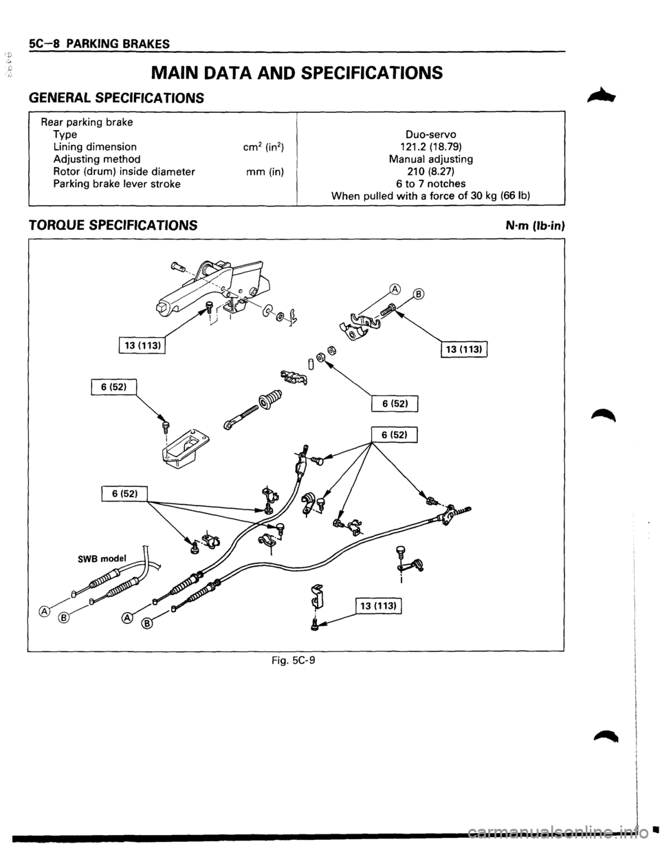
MAIN DATA AND SPECIFICATIONS
GENERAL SPECIFICATIONS
Rear parking brake
Type Lining dimension
Adjusting method
Rotor (drum) inside diameter
Parking brake
lever stroke
mm (in) Duo-servo
121.2
(18.79)
Manual adjusting
210 (8.27)
6 to 7 notches
When pulled
with a force of 30 kg (66 lb)
TORQUE SPECIFICATIONS N·m (lb·in}
Fig. 5C-9
•
Page 1368 of 1928
8 -178 CHASSIS ELECTRICAL
ANTI-LOCK BRAKE SYSTEM (ABS)
GENERAL DESCRIPTION
The circuit consists of the starter switch, stoplight switch (vehicle w/o cruise control), brake switch (vehicle
with cruise control), hydraulic unit, electronic brake control module, wheel speed sensor, G sensor, ABS and
4WD indicator, 4WD switch and data link connector.
When the service brake is applied while in the running mode,
the EBCM (Electronic Brake Control Module)
judges
which wheel is about to lock by using the wheel rotation speed signals sent from the four ABS speed
sensors at the
front and rear wheels. And the brake fluid pressure applied to the four wheels is controlled by
a hydraulic unit to prevent the wheels from locking.
Based on the wheel rotation speed signals
input from the ABS sensor, the EBCM sends out signals to the
solenoid valve in the hydraulic unit
to increase, maintain or decrease the brake fluid pressure. The solenoid
valve uses this signal
to control the fluid pressure which is applied to the calipers of the disk brakes of the
front wheels. (The system also controls at the same time the fluid pressure applied to the rear wheels.)
• EBCM (Electronic brake control module)
The EBCM uses the signals sent from the speed sensor to control the operation of the hydraulic unit.
When any malfunction occurs in the ABS, the
EBCM activates the fail-safe fuction while turning on the
ABS warning light.
• Hydraulic unit
The hydraulic unit consists of the motor, plunger pump, solenoid valve, and fluid pressure control
valves. The exterior
of the unit has a relay box consisting of the motor relay and valve relay. Three
solenoid valves, the
two of which are provided at the front wheels and the one at the rear wheels, control
the fluid pressure
of these wheels.
• Speed sensor
The speed sensor consists of the sensor and the rotor. It sends the EBCM the AC voltage generated by
the rotation of the rotor as the vehicle speed signal. ~
• G-sensor
The G-sensor, installed inside the center console, sends out signals to the EBCM by detecting the
decelerating speed
of the vehicle.
• ABS warning light
The ABS warning light in the instrument panel, lights up when any malfunction occurs in the ABS. It also
lights up
with the starter key at the "ON" position, as a self-check.
Refer
to Section 5A4, "ANTI-LOCK BRAKE SYSTEM" for detail.
II