brake rotor ISUZU TROOPER 1995 User Guide
[x] Cancel search | Manufacturer: ISUZU, Model Year: 1995, Model line: TROOPER, Model: ISUZU TROOPER 1995Pages: 1928
Page 357 of 1928
ll .. •l INSPECTION AND REPAIR
Make necessary parts replacement, if wear, damage,
"'-"' corrosion or any other abnormal conditions are found
through inspection.
Check the following parts;
• Rotor
• Cylinder body
• Cylinder bore
• Piston
•
Guide bolt, Lock bolt
•
Support bracket
NOTE:
The piston seal, boot ring and dust boot are to be
replaced each time the caliper is overhauled. Discard
these used rubber parts and
replace with new ones.
l*!•l REASSEMBLY
9. Caliper body
8. Bleeder with cap
~~~ Torque N·m (lb·in) 8 (69)
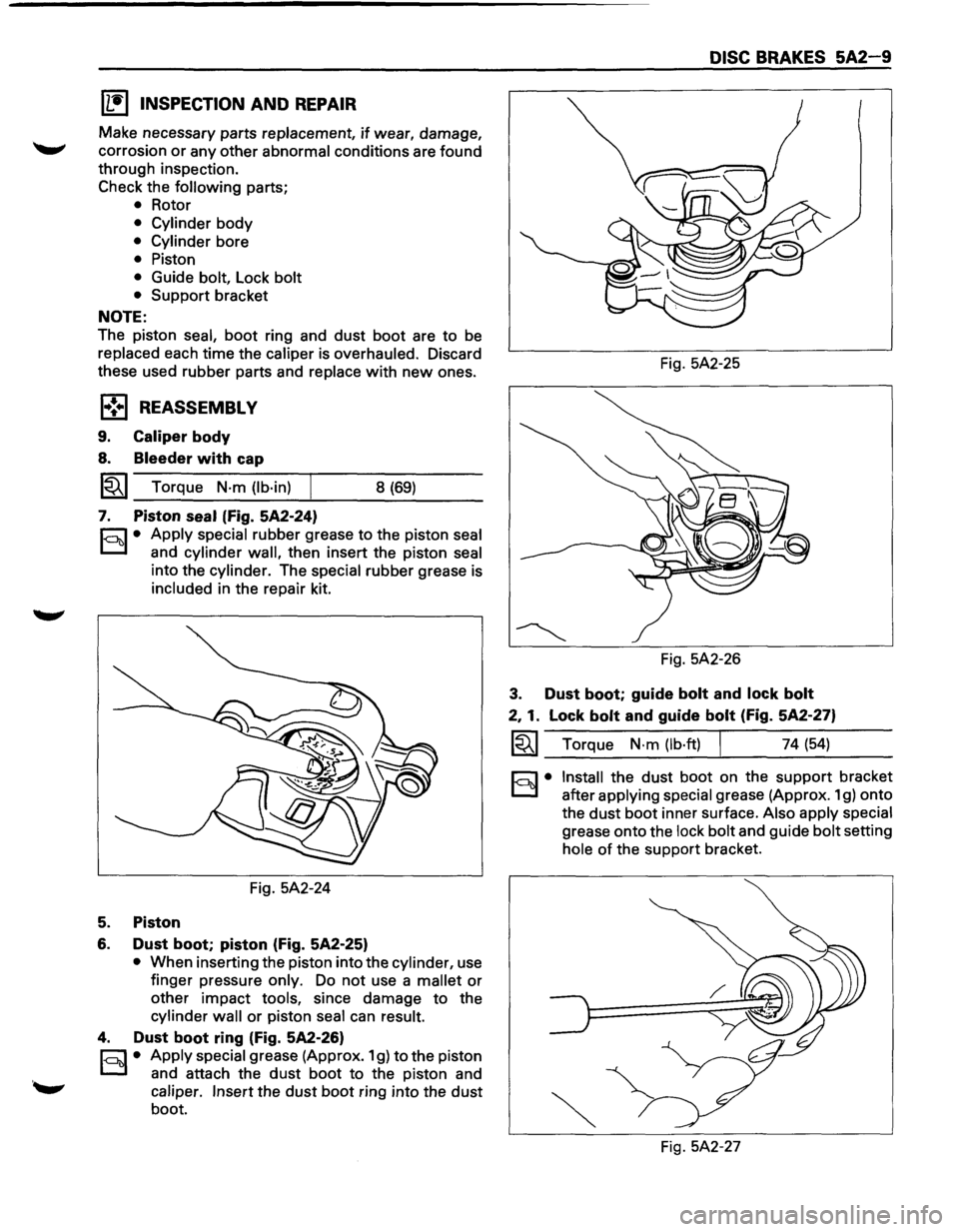
7. Piston seal (Fig. 5A2-24)
r.:;::'1 • Apply special rubber grease to the piston seal
0 and cylinder wall, then insert the piston seal
into the cylinder. The special rubber grease is
included in the repair kit.
Fig. 5A2-24
5. Piston
6. Dust boot; piston (Fig. 5A2-25)
• When inserting the piston into the cylinder, use
finger pressure
only. Do not use a mallet or
other impact tools, since damage to the
cylinder wall or piston seal can result.
4. Dust boot ring (Fig. 5A2-26)
r;::;:] • Apply special grease (Approx. 1 g) to the piston
0 and attach the dust boot to the piston and
caliper. Insert the dust boot ring into the dust
boot.
DISC BRAKES 5A2-9
Fig. 5A2-25
Fig. 5A2-26
3. Dust boot; guide bolt and lock bolt
2, 1. Lock bolt and guide bolt (Fig. 5A2-27)
~~~ Torque N·m (lb·ft) I 74 (54)
§)• Install the dust boot on the support bracket
after
applying special grease (Approx. 1 g) onto
the
dust boot inner surface. Also apply special
grease onto the lock bolt and guide bolt setting
hole of the support bracket.
Fig. 5A2-27
Page 358 of 1928
5A2-1 0 DISC BRAKES
REAR DISC BRAKE
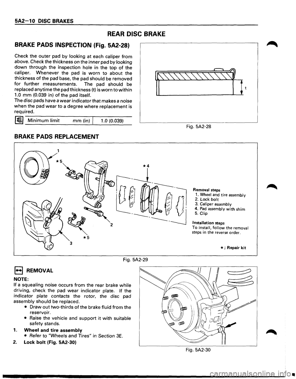
BRAKE PADS INSPECTION (Fig. 5A2-28)
Check the outer pad by looking at each caliper from
above. Check the thickness on the inner pad by looking
down through the inspection hole in the top of the
caliper. Whenever the pad is worn to about the
thickness
of the pad base, the pad should be removed
for further measurements. The pad should be
replaced anytime the pad thickness (t) is worn to within
1.0 mm (0.039 in) of the pad itself. 'f'-~1~
The disc pads have a wear indicator that makes a noise
when the pad wear to a degree where replacement is
required.
~~~-M--in-im __ u_m_l-im--it _____ m_m--(i-n)-rl--,-.-0-(0-.-03_9_) ___
BRAKE PADS REPLACEMENT
EJ REMOVAL
NOTE:
1
*5
3
Fig. 5A2-29
If a squealing noise occurs from the rear brake while
driving, check the pad wear indicator plate. If the
indicator
plate contacts the rotor, the disc pad
assembly should be replaced.
•
Draw out two-thirds of the brake fluid from the
reservoir.
• Raise the vehicle and support it with suitable
safety stands.
1. Wheel and tire assembly
•
Refer to "Wheels and Tires" in Section 3E.
2. Lock bolt (Fig. 5A2-30) Fig.
5A2-28
Removal steps
1. Wheel and tire assembly 2. Lock bolt 3. Caliper assembly
4. Pad assembly with shim 5. Clip
Installation
steps
To
install, follow the removal steps in the reverse order.
* ; Repair kit
Fig. 5A2-30
•
Page 360 of 1928
5A2-12 DISC BRAKES
1. Wheel and tire assembly
• Refer to "Wheels and Tires" in Section 3E.
• Pump the brake pedal several times to
make sure that the pedal
is firm. Check the
brake fluid level in the reservoir after
pumping the brakes.
SERVICING THE ROTOR
In the manufacturing of the brake rotor, all the
tolerances regarding surface finish, parallelism and
lateral runout are held very closely. The maintenance
of these tolerances provide the surface necessary to
assure smooth brake operation.
LATERAL RUNOUT
Lateral runout is the movement of the rotor from side
to side as it rotates on the spindle. This could also be
referred
to as "rotor wobble".
This movement causes the piston to be knocked back
into its bore. This
results in additional pedal travel and
a vibration during braking.
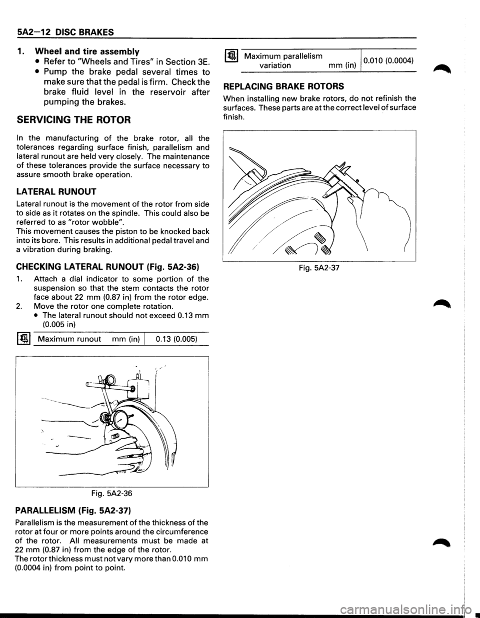
CHECKING LATERAL RUNOUT (Fig. 5A2-36)
1. Attach a dial indicator to some portion of the
suspension so
that the stem contacts the rotor
face about 22 mm (0.87 in) from the rotor edge.
2. Move the rotor one complete rotation.
• The lateral runout should not exceed 0.13 mm
(0.005 in)
~~~ Maximum runout mm (in) I 0.13 (0.005)
Fig. 5A2-36
PARALLELISM (Fig. 5A2-37)
Parallelism is the measurement of the thickness of the
rotor at
four or more points around the circumference
of the rotor. All measurements must be made at
22 mm (0.87 in) from the edge of the rotor.
The rotor thickness
must not vary more than 0.010 mm
(0.0004 in) from point to point.
Maximum parallelism variation mm (in) 0
·01 0 (0.000 4
)
REPLACING BRAKE ROTORS
When installing new brake rotors, do not refinish the
surfaces. These parts are at the correct
level of surface
finish.
Fig. 5A2-37
Page 361 of 1928
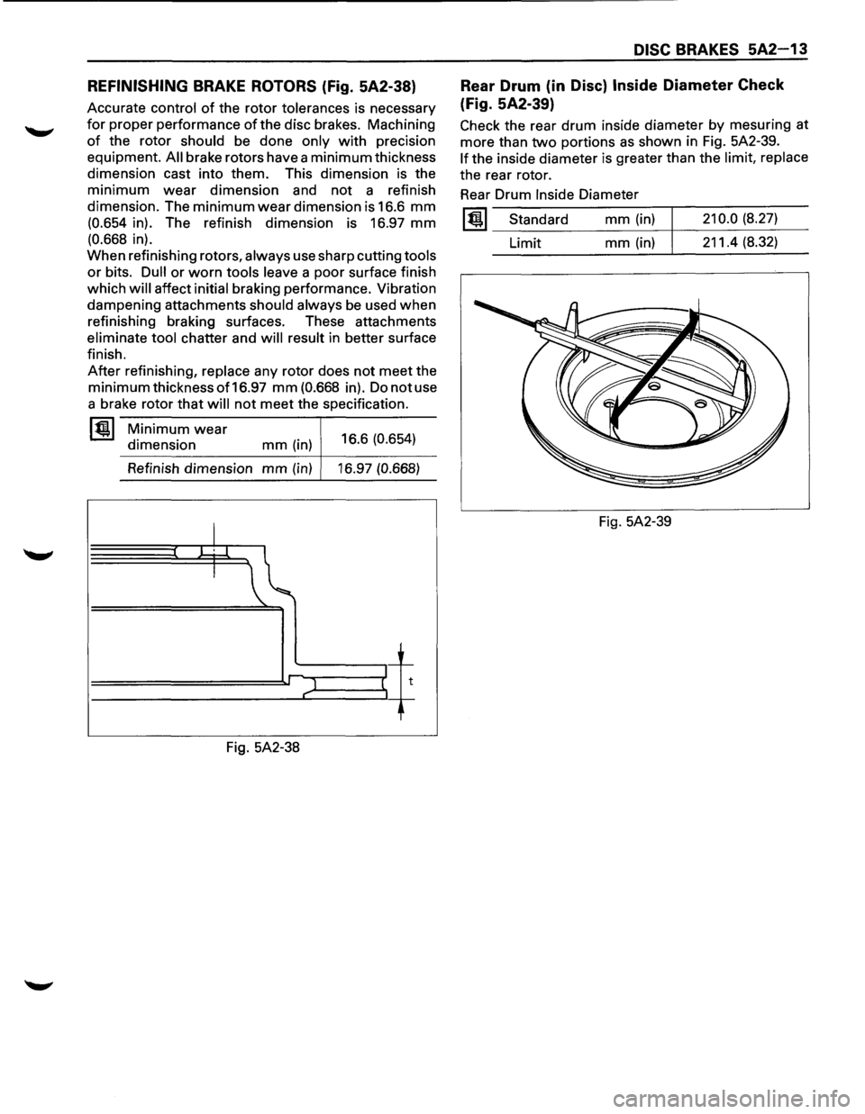
REFINISHING BRAKE ROTORS (Fig. 5A2-38)
Accurate control of the rotor tolerances is necessary
for proper performance of the disc brakes. Machining
of the rotor should be done only with precision
equipment.
All brake rotors have a minimum thickness
dimension cast into them. This dimension is the
minimum wear dimension and not a refinish
dimension. The
minimum wear dimension is 16.6 mm
(0.654 in). The refinish dimension is 16.97 mm
(0.668 in).
When refinishing rotors,
always use sharp cutting tools
or bits. Dull or worn tools leave a poor surface finish
which
will affect initial braking performance. Vibration
dampening attachments
should always be used when
refinishing braking surfaces. These attachments
eliminate tool chatter and will result in better surface
finish.
After refinishing, replace any rotor does not meet the
minimum thickness of 16.97 mm (0.668 in). Do not use
a brake rotor
that will not meet the specification.
~ Minimum wear
dimension mm (in) 16.6 (0.654)
Refinish dimension
mm (in) 16.97 (0.668)
I W.l.
I
~t
l t"
Fig. 5A2-38
DISC BRAKES 5A2-13
Rear Drum (in Disc) Inside Diameter Check
(Fig. 5A2-39)
Check the rear drum inside diameter by mesuring at
more than
two portions as shown in Fig. 5A2-39.
If the inside diameter is greater than the limit, replace
the rear rotor.
Rear Drum
Inside Diameter
lt!l Standard
Limit mm (in)
mm (in)
Fig. 5A2-39
210.0 (8.27)
211.4 (8.32)
Page 366 of 1928
![ISUZU TROOPER 1995 User Guide 5A2-18 DISC BRAKES
(1!] INSPECTION AND REPAIR
Make necessary parts replacement, if wear, damage,
corrosion
or any other abnormal conditions are found
through inspection.
Check the
followi](/img/61/57183/w960_57183-365.png "ISUZU TROOPER 1995 User Guide 5A2-18 DISC BRAKES
(1!] INSPECTION AND REPAIR
Make necessary parts replacement, if wear, damage,
corrosion
or any other abnormal conditions are found
through inspection.
Check the
followi")
5A2-18 DISC BRAKES
(1!] INSPECTION AND REPAIR
Make necessary parts replacement, if wear, damage,
corrosion
or any other abnormal conditions are found
through inspection.
Check the
following parts;
• Rotor
• Cylinder body
• Cylinder bore
• Piston
• Slide
pin
• Support bracket
NOTE:
The piston dust seal and dust boot are to be replaced
each time the caliper is overhauled. Discard these
used rubber parts and
replace with new ones.
1•! .. 1 REASSEMBLY
9. Caliper body
8. Bleeder with cap
1~1 Torque N·m (lb·in) 8 (69)
7. Piston seal (Fig. 5A2-51)
r:::;] • Apply special rubber grease to the piston seal
D and cylinder wall, then insert the piston seal
into the cylinder. The special rubber grease is
included in the repair kit.
Fig. 5A2-51
5. Piston
6. Dust boot; piston (Fig. 5A2-52)
• When inserting the piston into the cylinder, use
finger pressure
only. Do not use a mallet or
other impact tools, since damage to the
cylinder wall or piston seal can result.
4. Dust boot ring (Fig. 5A2-53)
r:::;] • Apply special grease (Approx. 1 g) to the piston
D and attach the dust boot to the piston and
caliper. Insert the dust boot ring into the dust
boot. Fig.
5A2-52
Fig. 5A2-53
3. Dust boot (Fig. 5A2-54)
r:::;] • Install the dust boot on the support bracket
D after applying special grease (Approx. 1 g) onto
the dust
boot inner surface. Also apply special
grease onto the lock bolt and guide bolt setting
hole of the support bracket.
2. Lock bolt
1. Guide bolt
Fig. 5A2-54
~~~ Torque N-m (lb·ft) 44 (32)
•
Page 414 of 1928
5A4-4 4-WHEEL ANTILOCK BRAKE SYSTEM (ABS)
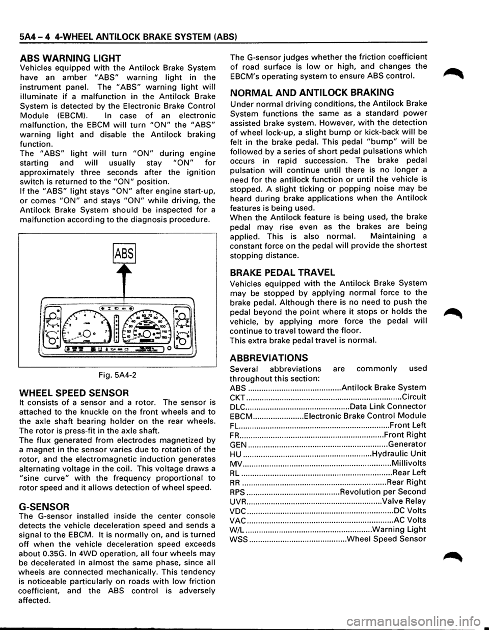
ABS WARNING LIGHT
Vehicles equipped with the Antilock Brake System
have an
amber "ABS" warning light in the
instrument panel. The "ABS" warning light will
illuminate if a malfunction in the Antilock Brake
System is detected by the Electronic Brake
Control
Module (EBCM). In case of an electronic
malfunction, the EBCM will turn "ON" the "ABS"
warning light and disable the Antilock braking
function.
The
"ABS" light will turn "ON" during engine
starting and
will usually stay "ON" for
approximately three seconds after the ignition
switch is returned to the "ON" position.
If the "ABS" light stays "ON" after engine start-up,
or comes "ON" and stays "ON" while driving, the
Antilock Brake System should be inspected
for a
malfunction according to the diagnosis procedure.
Fig. 5A4-2
WHEEL SPEED SENSOR
It consists of a sensor and a rotor. The sensor is
attached
to the knuckle on the front wheels and to
the axle shaft bearing holder on the rear wheels.
The
rotor is press-fit in the axle shaft.
The
flux generated from electrodes magnetized by
a magnet in the sensor varies due to rotation of the
rotor, and the electromagnetic
induction generates
alternating voltage in
the coil. This voltage draws a
"sine curve" with the frequency proportional to
rotor speed and it allows detection of wheel speed.
G-SENSOR
The G-sensor installed inside the center console
detects the vehicle deceleration speed and sends a
signal
to the EBCM. It is normally on, and is turned
off when the vehicle deceleration speed exceeds
about 0.35G.
In 4WD operation, all four wheels may
be decelerated in almost the same phase, since all
wheels are connected mechanically. This tendency
is noticeable particularly on roads
with low friction
coefficient, and the
ABS control is adversely
affected. The
G-sensor judges
whether the friction coefficient
of road surface is low or high, and changes the
EBCM's operating system to ensure ABS control.
NORMAL AND ANTILOCK BRAKING
Under normal driving conditions, the Antilock Brake
System functions the same
as a standard power
assisted brake system. However, with the detection
of wheel lock-up, a slight bump or kick-back will be
felt in the brake pedal. This pedal
"bump" will be
followed by a series of short pedal pulsations which
occurs in rapid succession. The brake pedal
pulsation
will continue until there is no longer a
need
for the antilock function or until the vehicle is
stopped. A
slight ticking or popping noise may be
heard
during brake applications when the Antilock
features is being used.
When the
Antilock feature is being used, the brake
pedal
may rise even as the brakes are being
applied. This is also
normal. Maintaining a
constant force on the pedal
will provide the shortest
stopping distance.
BRAKE PEDAL TRAVEL
Vehicles equipped with the Antilock Brake System
may be stopped by applying normal force to the
brake pedal.
Although there is no need to push the
pedal beyond the
point where it stops or holds the ~
vehicle, by applying more force the pedal will
continue to travel toward the floor.
This extra brake pedal travel is normal.
ABBREVIATIONS
Several abbreviations are commonly used
throughout this section:
ABS .......................................... Antilock Brake System
CKT ...................................................................... Circuit
DLC ............................................... Data Link Connector
EBCM ....................... Eiectronic Brake Control Module
FL. ................................................................... Front Left
FR ................................................................. Front Right
GEN ............................................................... Generator
HU .......................................................... Hydraulic Unit
MV ................................................................... Millivolts
RL .................................................................... Rear Left
RR ................................................................. Rear Right
RPS .......................................... Revolution per Second
UVR ............................................................. Valve Relay
VDC .................................................................. DC Volts
VAC .................................................................. AC Volts
W/L .........................................................
Warning Light
WSS ............................................ Wheel Speed Sensor
Page 418 of 1928
5A4-8 4-WHEEL ANTILOCK BRAKE SYSTEM (ABS)
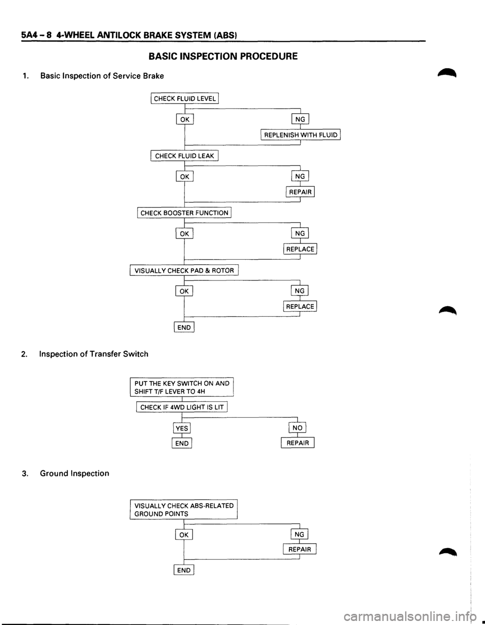
BASIC INSPECTION PROCEDURE
1. Basic Inspection of Service Brake
VISUALL V CHECK PAD & ROTOR
2. Inspection of Transfer Switch
3. Ground Inspection
PUT THE KEY SWITCH ON AND
SHIFT T/F LEVER TO 4H
CHECK IF 4WD LIGHT IS LIT
VISUALL
V CHECK ASS-RELATED
GROUND POINTS
•
Page 441 of 1928
4-WHEEL ANTILOCK BRAKE SYSTEM (ABS) 5A4-31
MODE F6: WHEEL SENSORS
When conducting the wheel sensor test, note the following:
1) Accelerate vehicle only slightly above 20 km/h (12 mph).
2) When this speed is attained, put transmission into neutral and allow vehicle to coast to a halt. (Parking
brake may be engaged slightly.)
3) When vehicle is at a standstill, actuate either foot brake or parking brake.
When the
wheel speed sensor test is being performed, the output or speed value of all four sensors is
monitored
by TECH 1. When the output of wheel sensors becomes too low to convert into speed value, the
last known vehicle speed is displayed and the values are fixed. If wheel sensors are normal, it is at the
vehicle speed
of 5 km/h (3 mph) or less that their output is lost. Therefore, if all the fixed speed values are
less than 5 km/h (3 mph), the wheel sensors are normal. If one or more of the four speed values is more
than 5 km/h
(3 mph), it suggests that the following abnormalities have occurred to the sensor(s):
1. Excess gap between the sensor and sensor rotor.
2. Broken or damaged sensor rotor teeth.
3. Momentary open in sensor harness.
Page 477 of 1928
4-WHEEL ANTILOCK BRAKE SYSTEM (ABS) 5A4-67
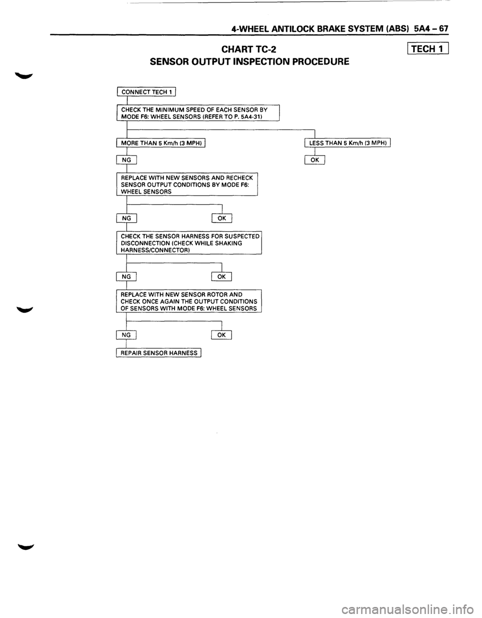
CHARTTC-2
SENSOR OUTPUT INSPECTION PROCEDURE
CHECK THE MINIMUM SPEED OF EACH SENSOR BY MODE F6: WHEEL SENSORS (REFER TOP. 5A4-31)
REPLACE
WITH NEW SENSORS AND RECHECK SENSOR OUTPUT CONDITIONS BY MODE F6: WHEEL SENSORS
CHECK THE
SENSOR HARNESS FOR SUSPECTED
DISCONNECTION (CHECK WHILE SHAKING HARNESS/CONNECTOR)
REPLACE
WITH NEW SENSOR ROTOR AND CHECK ONCE AGAIN THE OUTPUT CONDITIONS OF SENSORS WITH MODE F6: WHEEL SENSORS
I TECH 1 I
Page 491 of 1928
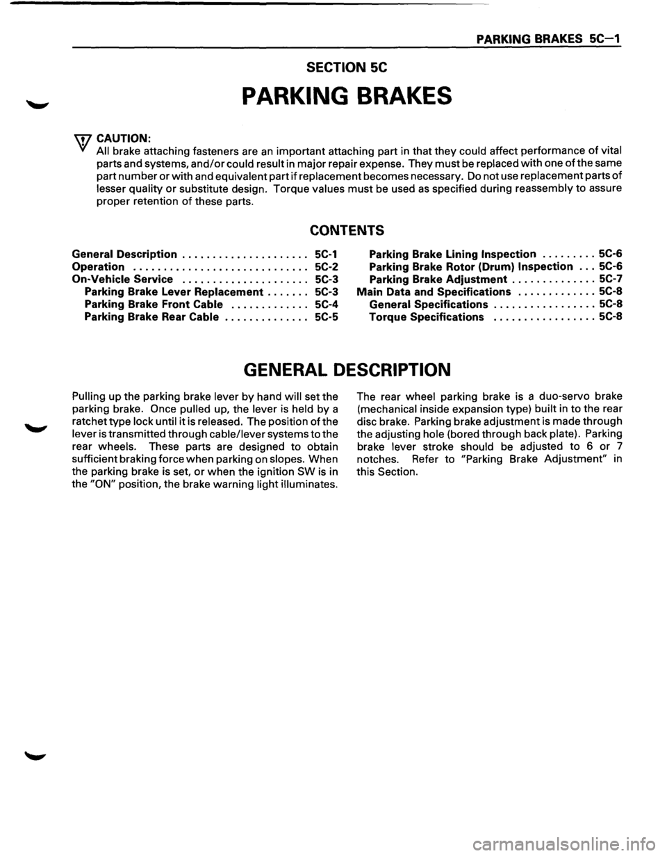
PARKING BRAKES 5C-1
SECTION 5C
PARKING BRAKES
'\f7 CAUTION:
Yf All brake attaching fasteners are an important attaching part in that they could affect performance of vital
parts and systems, and/or could result in major repair expense. They must be replaced with one ofthe same
part number
or with and equivalent part if replacement becomes necessary. Do not use replacement parts of
lesser quality or substitute design. Torque values must be used as specified during reassembly to assure
proper retention
of these parts.
CONTENTS
General Description ..................... 5C-1
Operation . . . . . . . . . . . . . . . . . . . . . . . . . . . . . 5C-2
On-Vehicle Service
..................... 5C-3
Parking Brake Lever Replacement . .
. . . . .
5C-3
Parking Brake Front Cable . .
. . . . . . . . . . .
5C-4
Parking Brake Rear Cable . .
. . . . . . . . . . . .
5C-5
Parking Brake Lining Inspection ......... 5C-6
Parking Brake Rotor (Drum) Inspection ... 5C-6
Parking Brake Adjustment .............. 5C-7
Main Data and Specifications ............. 5C-8
General
Specifications ................. 5C-8
Torque Specifications ................. 5C-8
GENERAL DESCRIPTION
Pulling up the parking brake lever by hand will set the
parking brake.
Once pulled up, the lever is held by a
ratchet type
lock until it is released. The position of the
lever is transmitted through cable/lever systems to the
rear
wheels. These parts are designed to obtain
sufficient braking force
when parking on slopes. When
the parking brake is set,
or when the ignition SW is in
the
"ON" position, the brake warning light illuminates.
The rear wheel parking brake is a duo-servo brake
(mechanical inside expansion type) built in to the rear
disc brake. Parking brake adjustment is made through
the adjusting
hole (bored through back plate). Parking
brake
lever stroke should be adjusted to 6 or 7
notches. Refer
to "Parking Brake Adjustment" in
this Section.