fuel type ISUZU TROOPER 1995 Workshop Manual
[x] Cancel search | Manufacturer: ISUZU, Model Year: 1995, Model line: TROOPER, Model: ISUZU TROOPER 1995Pages: 1928
Page 21 of 1928
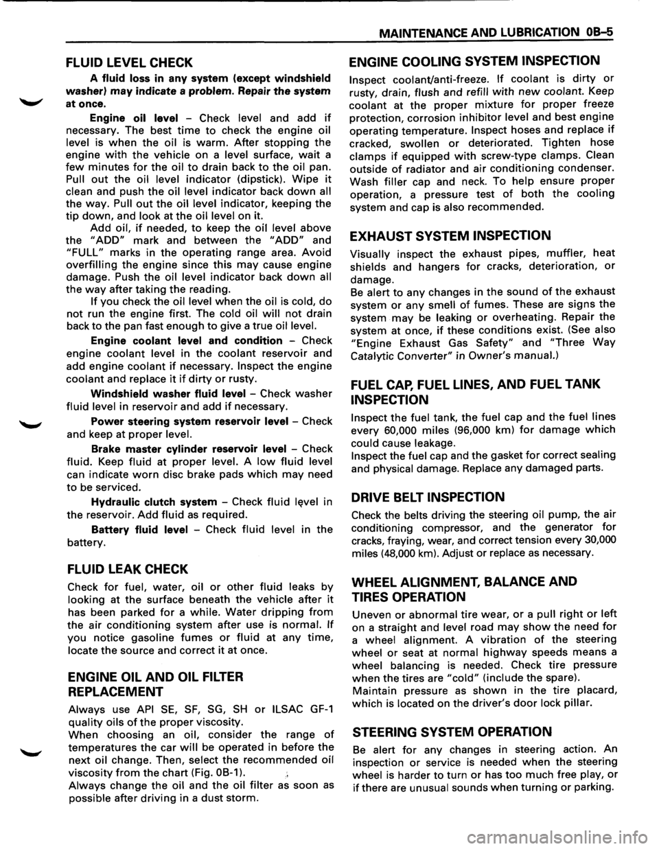
FLUID LEVEL CHECK
A fluid loss in any system (except windshield
washer) may indicate a problem. Repair the system
at once.
Engine
oil level -Check level and add if
necessary. The best time to check the engine oil
level is
when the oil is warm. After stopping the
engine with the vehicle on a level surface, wait a
few minutes for the oil to drain back to the oil pan.
Pull
out the oil level indicator (dipstick). Wipe it
clean and push the oil level indicator back down all
the
way. Pull out the oil level indicator, keeping the
tip down, and look at the oil level on it.
Add oil, if needed, to keep the oil level above
the
"ADD" mark and between the "ADD" and
"FULL" marks in the operating range area. Avoid
overfilling the engine since this may cause engine
damage. Push
the oil level indicator back down all
the
way after taking the reading.
If you check the oil level when the oil is cold, do
not run the engine first. The cold oil will not drain
back
to the pan fast enough to give a true oil level.
Engine coolant level and condition -Check
engine coolant level in the coolant reservoir and
add engine
coolant if necessary. Inspect the engine
coolant and replace it if dirty or rusty.
Windshield washer fluid level -Check washer
fluid level in reservoir and add if necessary.
Power steering system reservoir level-Check
and keep at
proper level.
Brake master cylinder reservoir level -Check
fluid. Keep fluid at proper level. A low fluid level
can indicate
worn disc brake pads which may need
to be serviced.
Hydraulic clutch system -Check fluid l~vel in
the reservoir.
Add fluid as required.
Battery fluid level -Check fluid level in the
battery.
FLUID LEAK CHECK
Check for fuel, water, oil or other fluid leaks by
looking at the surface beneath the vehicle after it
has been parked for a while. Water dripping from
the air conditioning system after use is normal. If
you notice gasoline fumes or fluid at any time,
locate the source and correct it at once.
ENGINE OIL AND OIL FILTER
REPLACEMENT
Always use API SE, SF, SG, SH or ILSAC GF-1
quality oils of the proper viscosity.
When choosing an oil, consider the range of
temperatures the car will be operated in before the
next oil change. Then, select the recommended oil
viscosity
from the chart (Fig. OB-1).
Always change the oil and the oil filter as soon as
possible after driving in a dust storm.
MAINTENANCE AND LUBRICATION OB-5
ENGINE COOLING SYSTEM INSPECTION
Inspect coolant/anti-freeze. If coolant is dirty or
rusty, drain, flush and refill with new coolant. Keep
coolant at the proper mixture for proper freeze
protection,
corrosion inhibitor level and best engine
operating temperature.
Inspect hoses and replace if
cracked, swollen or deteriorated. Tighten hose
clamps if equipped with screw-type clamps. Clean
outside of radiator and air conditioning condenser.
Wash
filler cap and neck. To help ensure proper
operation, a pressure test of both the cooling
system and cap is also recommended.
EXHAUST SYSTEM INSPECTION
Visually inspect the exhaust pipes, muffler, heat
shields and hangers
for cracks, deterioration, or
damage.
Be alert to any changes in the sound of the exhaust
system
or any smell of fumes. These are signs the
system may be leaking or overheating. Repair the
system at once,
if these conditions exist. (See also
"Engine Exhaust Gas Safety" and "Three Way
Catalytic Converter" in Owner's manual.)
FUEL CAP, FUEL LINES, AND FUEL TANK
INSPECTION
Inspect the fuel tank, the fuel cap and the fuel lines
every
60,000 miles (96,000 km) for damage which
could cause leakage.
Inspect the fuel cap and the gasket for correct sealing
and physical damage. Replace any damaged parts.
DRIVE BELT INSPECTION
Check the belts driving the steering oil pump, the air
conditioning compressor, and the generator
for
cracks, fraying, wear, and correct tension every 30,000
miles (48,000 km). Adjust or replace as necessary.
WHEEL ALIGNMENT, BALANCE AND
TIRES OPERATION
Uneven or abnormal tire wear, or a pull right or left
on a straight and level road may show the need for
a wheel alignment. A vibration of the steering
wheel or seat at normal highway speeds means a
wheel balancing is needed. Check tire pressure
when the tires are "cold" (include the spare).
Maintain pressure as shown in the tire placard,
which is located on the driver's door lock pillar.
STEERING SYSTEM OPERATION
Be alert for any changes in steering action. An
inspection
or service is needed when the steering
wheel is harder
to turn or has too much free play, or
if there are unusual sounds when turning or parking.
Page 24 of 1928
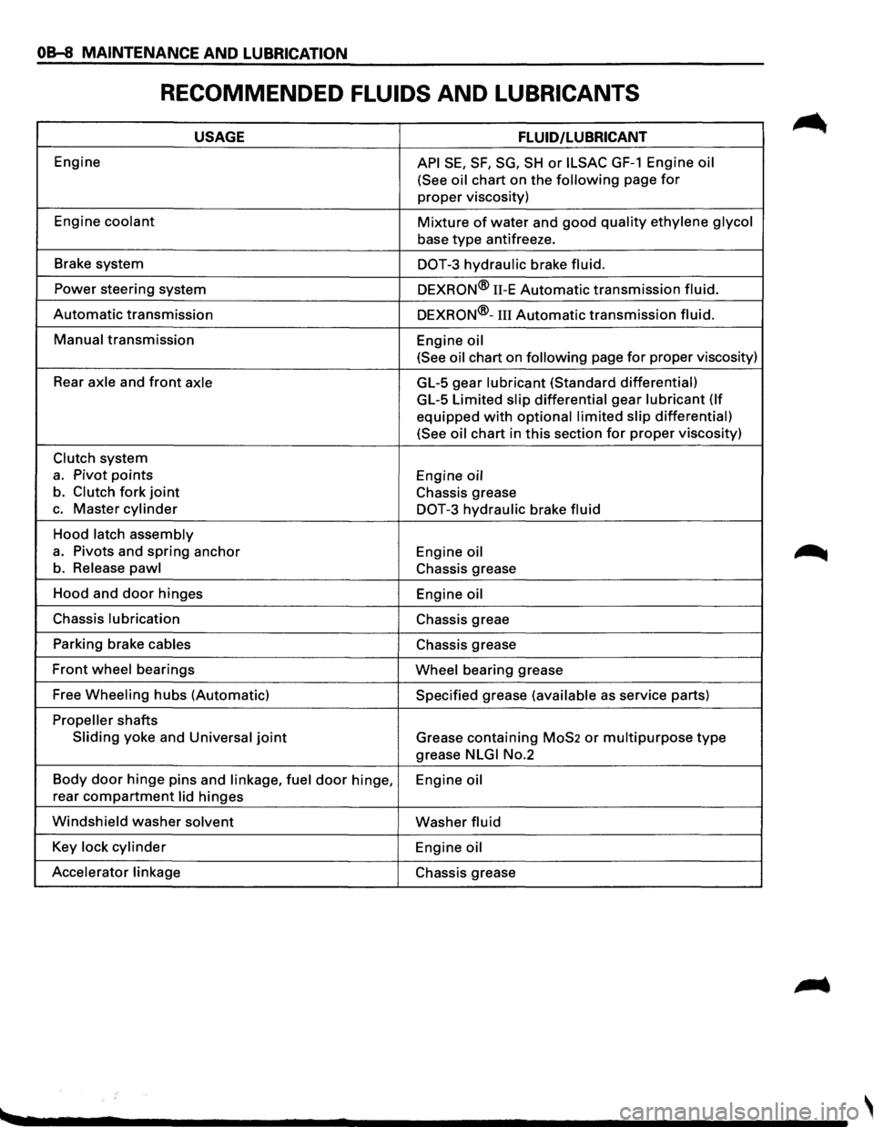
OB-8 MAINTENANCE AND LUBRICATION
RECOMMENDED FLUIDS AND LUBRICANTS
USAGE FLUID/LUBRICANT
Engine API SE, SF, SG, SH or ILSAC GF-1 Engine oil
(See oil
chart on the following page for
proper viscosity)
Engine
coolant Mixture of water and good quality ethylene glycol
base type antifreeze.
Brake system
DOT-3 hydraulic brake fluid.
Power steering system
DEXRON® 11-E Automatic transmission fluid.
Automatic transmission DEXRON®-III Automatic transmission fluid.
Manual transmission
Engine oil
(See oil
chart on following page for proper viscosity)
Rear
axle and front axle GL-5 gear lubricant (Standard differential)
GL-5 Limited slip differential gear lubricant (If
equipped with optional limited slip differential)
(See oil
chart in this section for proper viscosity)
Clutch system
a. Pivot points Engine oil
b. Clutch fork joint Chassis grease
c. Master cylinder DOT-3 hydraulic brake fluid
Hood latch assembly
a. Pivots and spring anchor
Engine oil
b. Release pawl Chassis grease
Hood and
door hinges
Engine oil
Chassis lubrication Chassis greae
Parking brake
cables Chassis grease
Front wheel bearings Wheel bearing grease
Free
Wheeling hubs (Automatic) Specified grease (available as service parts)
Propeller shafts
Sliding yoke and Universal joint Grease containing MoS2 or multipurpose type
grease NLGI No.2
Body
door hinge pins and linkage, fuel door hinge,
Engine oil
rear compartment lid hinges
Windshield washer solvent Washer fluid
Key lock cylinder Engine oil
Accelerator linkage
Chassis grease
Page 499 of 1928
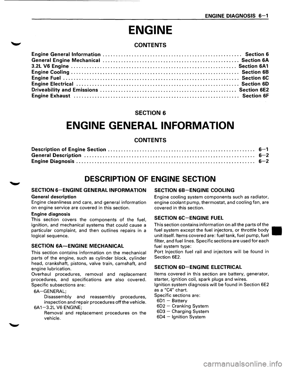
ENGINE DIAGNOSIS S-1
ENGINE
CONTENTS
Engine General Information . . . . . . . . . . . . . . . . . . . . . . . . . . . . . . . . . . . . . . . . . . . . . . . . . . . . . Section S
General
Engine Mechanical .................................................... Section SA
3.2L VS Engine ............................................................... Section SA1
Engine Cooling . . . . . . . . . . . . . . . . . . . . . . . . . . . . . . . . . . . . . . . . . . . . . . . . . . . . . . . . . . . . . . . . Section S8
Engine Fuel . . . . . . . . . . . . . . . . . . . . . . . . . . . . . . . . . . . . . . . . . . . . . . . . . . . . . . . . . . . . . . . . . . . Section SC
Engine Electrical . . . . . . . . . . . . . . . . . . . . . . . . . . . . . . . . . . . . . . . . . . . . . . . . . . . . . . . . . . . . . . Section SD
Driveability and Emissions . . . . . . . . . . . . . . . . . . . . . . . . . . . . . . . . . . . . . . . . . . . . . . . . . . . . Section SE2
Engine Exhaust . . . . . . . . . . . . . . . . . . . . . . . . . . . . . . . . . . . . . . . . . . . . . . . . . . . . . . . . . . . . . . . Section SF
SECTION 6
ENGINE GENERAL INFORMATION
CONTENTS
Description of Engine Section . . . . . . . . . . . . . . . . . . . . . . . . . . . . . . . . . . . . . . . . . . . . . . . . . . . . . . . . S-1
General Description . . . . . . . . . . . . . . . . . . . . . . . . . . . . . . . . . . . . . . . . . . . . . . . . . . . . . . . . . . . . . . . . . S-2
Engine Diagnosis . . . . . . . . . . . . . . . . . . . . . . . . . . . . . . . . . . . . . . . . . . . . . . . . . . . . . . . . . . . . . . . . . . . . S-2
DESCRIPTION OF ENGINE SECTION
SECTIONS-ENGINE GENERAL INFORMATION SECTION S8-ENGINE COOLING
General description
Engine cleanliness and care, and general information
on engine service are covered in this section.
Engine diagnosis
This section covers the components of the fuel,
ignition, and mechanical systems that could cause a
particular complaint, and then outlines repairs in a
logical sequence.
SECTION SA-ENGINE MECHANICAL
This section contains information on the mechanical
parts of the engine, such as cylinder block, cylinder
head, crankshaft, pistons, valve train, camshaft, and
engine
lubrication.
Overhaul
procedures, removal and replacement
procedures, and specifications are also covered.
Specific subsections are:
SA-GENERAL;
Disassembly and reassembly procedures,
inspection and repair procedures
off the vehicle.
6A 1-3.2L V6 ENGINE;
Removal
and replacement procedures on the
vehicle.
Engine cooling system components such as radiator,
engine
coolant pump, thermostat, and cooling fan, are
covered
in this section.
SECTION SC-ENGINE FUEL
This section contains information on all the parts of the
fuel system except the fuel injectors, or throttle body II
unit itself. Items covered are: fuel tank, fuel pump, fuel
filter,
and fuel lines. Specific sections are used for each
fuel system type:
Port
Injection fuel rail and injectors will be found in
Section
6E2.
SECTION SD-ENGINE ELECTRICAL
Items covered in this section are battery, generator,
starter, ignition
coil, spark plugs and wires.
Ignition system diagnosis will be found in Section 6E2
as a "C4" chart.
Specific sections are:
601 -Battery
602 - Cranking System
603 -Charging System
604 -Ignition System
Page 504 of 1928
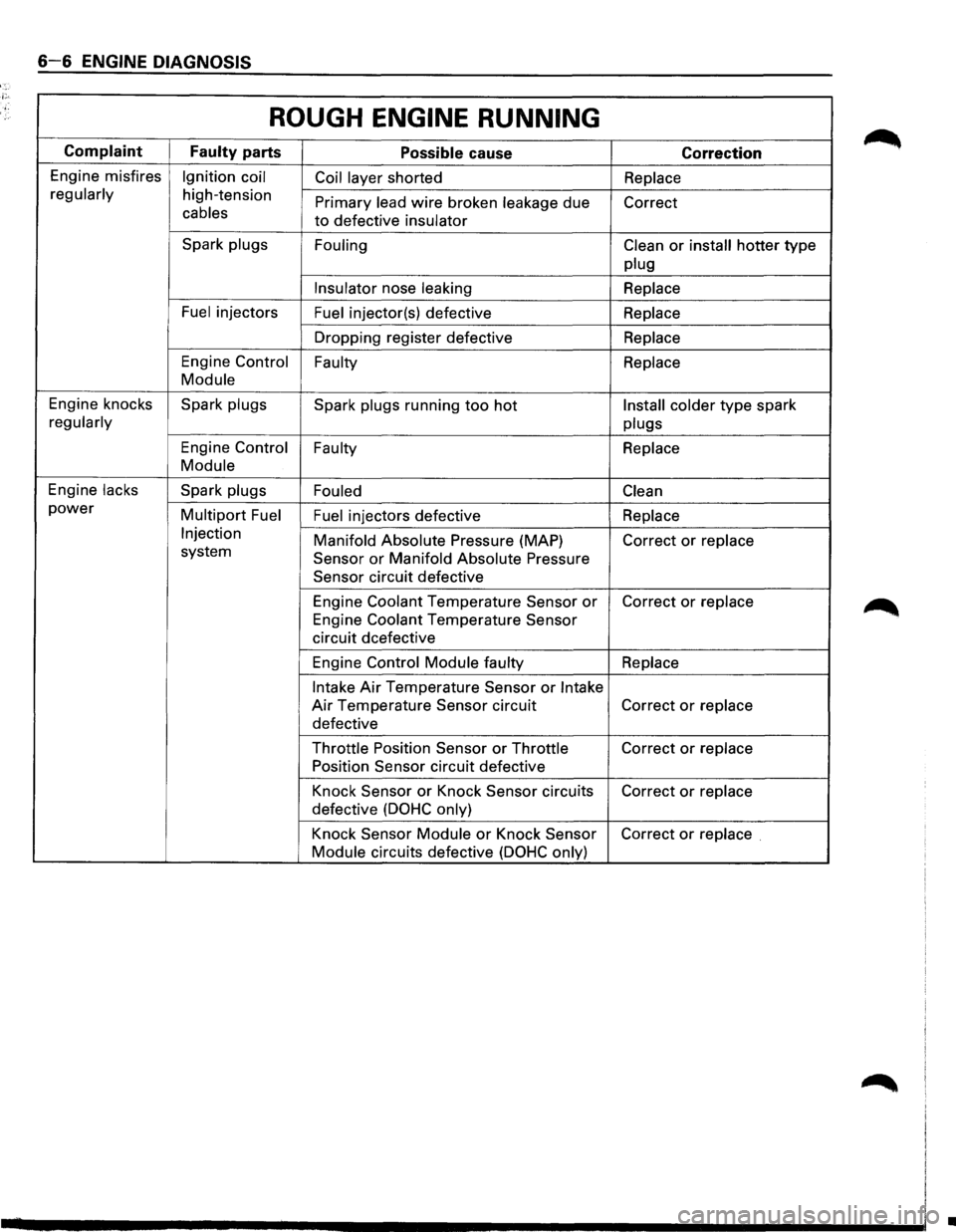
6-6 ENGINE DIAGNOSIS
ROUGH ENGINE RUNNING
Complaint
Faulty parts Possible cause Correction
Engine misfires Ignition coil
Coil layer shorted Replace
regularly
high-tension Primary lead wire broken leakage due
Correct cables to defective insulator
Spark plugs
Fouling Clean
or install hotter type
plug
Insulator
nose leaking Replace
Fuel
injectors Fuel injector(s) defective Replace
Dropping register defective Replace
Engine Control
Faulty Replace
Module
Engine knocks Spark plugs
Spark plugs running too hot Install colder type spark
regularly
plugs
Engine Control Faulty
Replace
Module
Engine lacks Spark plugs
Fouled Clean
power Multipart Fuel
Fuel injectors defective Replace
Injection Manifold Absolute Pressure (MAP)
Correct or replace system Sensor or Manifold Absolute Pressure
Sensor
circuit defective
Engine
Coolant Temperature Sensor or Correct or replace
Engine Coolant Temperature Sensor
circuit dcefective
Engine
Control Module faulty Replace
Intake
Air Temperature Sensor or Intake
Air Temperature Sensor circuit Correct or replace
defective
Throttle Position Sensor or Throttle Correct or replace
Position Sensor
circuit defective
Knock
Sensor or Knock Sensor circuits Correct or replace
defective (DOHC only)
Knock Sensor Module or Knock Sensor Correct or replace .
Module
circuits defective (DOHC only)
•
Page 561 of 1928
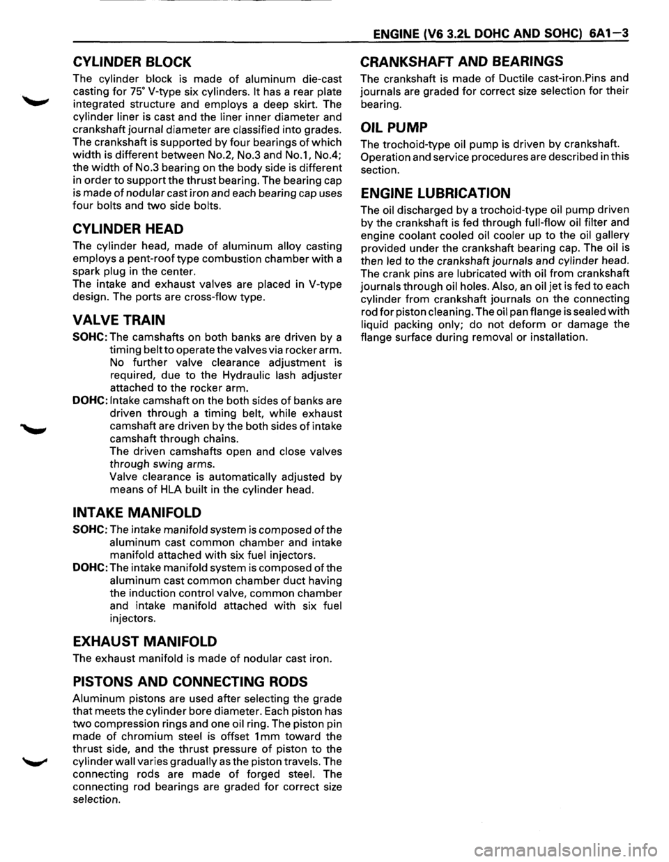
CYLINDER BLOCK
The cylinder block is made of aluminum die-cast
casting
for 75° V-type six cylinders. It has a rear plate
integrated structure and employs a deep skirt. The
cylinder liner is cast and the liner inner diameter and
crankshaft
journal diameter are classified into grades.
The crankshaft is supported by four bearings
of which
width is different between No.2, No.3 and No.1, No.4;
the
width of No.3 bearing on the body side is different
in order
to support the thrust bearing. The bearing cap
is made
of nodular cast iron and each bearing cap uses
four bolts and two side bolts.
CYLINDER HEAD
The cylinder head, made of aluminum alloy casting
employs a pent-roof type combustion chamber with a
spark
plug in the center.
The intake and exhaust
valves are placed in V-type
design. The ports are cross-flow type.
VALVE TRAIN
SOHC: The camshafts on both banks are driven by a
timing
belt to operate the valves via rocker arm.
No
further valve clearance adjustment is
required, due
to the Hydraulic lash adjuster
attachedtotherockerarm.
DOHC: Intake camshaft on the both sides of banks are
driven through a
timing belt, while exhaust
camshaft are driven by the both sides
of intake
camshaft through chains.
The driven camshafts open and
close valves
through swing arms.
Valve clearance is automatically adjusted by
means
of HLA built in the cylinder head.
INTAKE MANIFOLD
SOHC: The intake manifold system is composed ofthe
aluminum cast common chamber and intake
manifold attached with six fuel injectors.
DOHC: The intake manifold system is composed of the
aluminum cast common chamber duct having
the induction
control valve, common chamber
and intake
manifold attached with six fuel
injectors.
EXHAUST MANIFOLD
The exhaust manifold is made of nodular cast iron.
PISTONS AND CONNECTING RODS
Aluminum pistons are used after selecting the grade
that meets the cylinder bore diameter. Each piston has
two compression rings and one oil ring. The piston pin
made
of chromium steel is offset 1 mm toward the
thrust side, and the thrust pressure
of piston to the
cylinder wall varies gradually as the piston travels. The
connecting rods are made
of forged steel. The
connecting rod bearings are graded
for correct size
selection.
ENGINE (V6 3.2L DOHC AND SOHC) 6A1-3
CRANKSHAFT AND BEARINGS
The crankshaft is made of Ductile cast-iron.Pins and
journals are graded for correct size selection for their
bearing.
OIL PUMP
The trochoid-type oil pump is driven by crankshaft.
Operation and service procedures are described in this
section.
ENGINE LUBRICATION
The oil discharged by a trochoid-type oil pump driven
by the crankshaft is fed through full-flow oil filter and
engine
coolant cooled oil cooler up to the oil gallery
provided under the crankshaft bearing cap. The oil is
then
led to the crankshaft journals and cylinder head.
The crank pins are
lubricated with oil from crankshaft
journals through oil holes. Also, an oil jet is fed to each
cylinder from crankshaft journals on the connecting
rod
for piston cleaning. The oil pan flange is sealed with
liquid packing only; do not deform or damage the
flange surface during removal or installation.
Page 646 of 1928
![ISUZU TROOPER 1995 Workshop Manual 6C - 4 ENGINE FUEL
I1!]1NSPECTION
After installation, start engine and check for fuel leak
age.
IN-TANK FUEL FILTER
The filter is located on the lower end of fuel pickup
tube in the fuel tank](/img/61/57183/w960_57183-645.png "ISUZU TROOPER 1995 Workshop Manual 6C - 4 ENGINE FUEL
I1!]1NSPECTION
After installation, start engine and check for fuel leak
age.
IN-TANK FUEL FILTER
The filter is located on the lower end of fuel pickup
tube in the fuel tank")
6C - 4 ENGINE FUEL
I1!]1NSPECTION
After installation, start engine and check for fuel leak
age.
IN-TANK FUEL FILTER
The filter is located on the lower end of fuel pickup
tube in the fuel tank. It prevents dirt from entering the
fuel pipe and also stops water unless the filter is
completely submerged in the water. It is a self-cleaning
type, not requiring scheduled maintenance. Excess
water and sediment in the tank restricts fuel supply to
the engine, resulting in engine stop. In such a case, the
tank
must be cleaned throughly.
FUEL PUMP FLOW TEST
If reduction of fuel supply is suspected, perform
checking as follows.
Preparation:
• Make sure that there is fuel in the tank.
• With the engine running, check the fuel feed
pipe and hose
from fuel tank to injector for
evidence of leakage.
Retighten, if pipe or hose connection is loose.
Also,
check pipes and hoses for squashing or
clogging.
1. Receive the hose from fuel feed pipe with a clean
container, and check for fuel pump flow rate.
2. Connect the pump relay terminals with a jumper
wire as shown and start the fuel pump to measure
delivery. (Fig. 6C-4)
W CAUTION:
Never generate sparks when connecting a jumper
wire.
Fig. 6C-4
Delivery Delivery
15 seconds 0.38
liters minimum
If the measure value is out of standard, conduct the
pressure test.
Pressure test
For the pressure test to the fuel system, see Section 6E
"Fuel Control System".
II
Page 692 of 1928
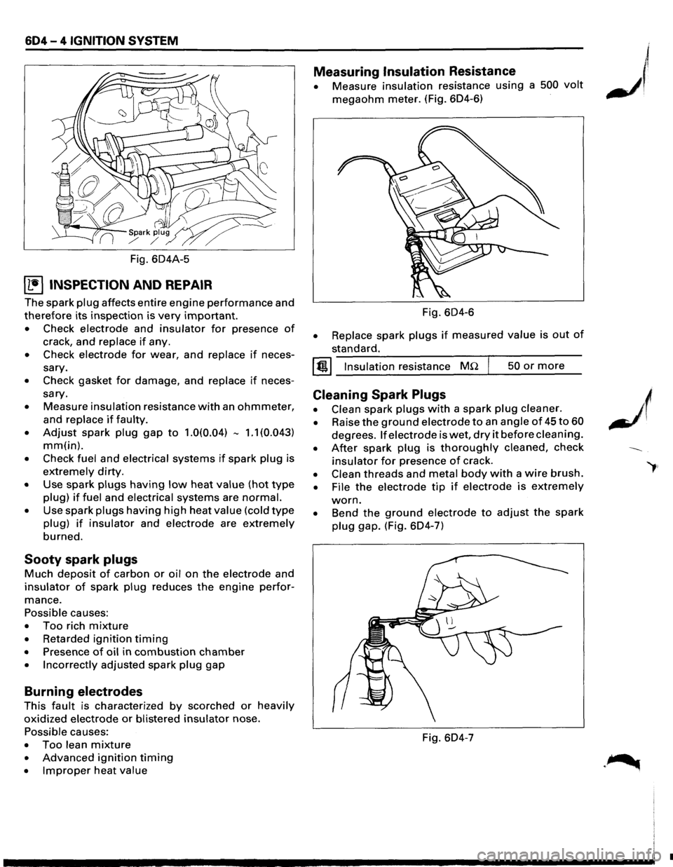
604-4 IGNITION SYSTEM
Fig. 604A-5
~ INSPECTION AND REPAIR
The spark plug affects entire engine performance and
therefore its inspection is very important.
• Check electrode and insulator for presence of
crack, and replace if any.
• Check electrode for wear, and replace if neces
sary.
• Check gasket for damage, and replace if neces
sary.
• Measure insulation resistance with an ohmmeter,
and replace if faulty.
• Adjust spark plug gap to 1.0(0.04) -1.1 (0.043)
mm(in).
• Check fuel and electrical systems if spark plug is
extremely dirty.
• Use spark plugs having low heat value (hot type
plug) if fuel and electrical systems are normal.
• Use spark plugs having high heat value (cold type
plug) if insulator and electrode are extremely
burned.
Sooty spark plugs
Much deposit of carbon or oil on the electrode and
insulator of spark plug reduces the engine perfor
mance.
Possible causes:
• Too rich mixture
• Retarded ignition timing
• Presence of oil in combustion chamber
• Incorrectly adjusted spark plug gap
Burning electrodes
This fault is characterized by scorched or heavily
oxidized electrode or blistered insulator nose.
Possible causes:
• Too lean mixture
• Advanced ignition timing
• Improper heat value
Measuring Insulation Resistance
• Measure insulation resistance using a 500 volt
megaohm meter. (Fig. 604-6)
Fig.
604-6
• Replace spark plugs if measured value is out of
standard.
I @!.j Insulation resistance MQ 50 or more
Cleaning Spark Plugs
• Clean spark plugs with a spark plug cleaner.
• Raise the ground electrode to an angle of 45 to 60
degrees. If electrode is wet, dry it before cleaning.
• After spark plug is thoroughly cleaned, check
insulator for presence of crack.
• Clean threads and metal body with a wire brush.
• File the electrode tip if electrode is extremely
worn.
• Bend the ground electrode to adjust the spark
plug gap. (Fig. 604-7)
Fig. 604-7
•
Page 707 of 1928
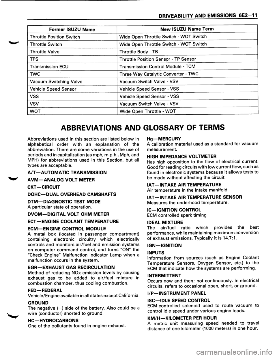
DRIVEABILITY AND EMISSIONS 6E2-11
Former ISUZU Name New ISUZU Name Term
Throttle Position Switch Wide Open Throttle Switch -WOT Switch
Throttle Switch
Wide Open Throttle Switch -WOT Switch
Throttle Valve Throttle
Body -TB
TPS Throttle Position Sensor -TP Sensor
Transmission ECU Transmission Control Module -TCM
TWC Three
Way
Catalytic Converter -TWC
Vacuum Switching Valve Vacuum Switch Valve -VSV
Vehicle Speed Sensor Vehicle
Speed Sensor
-VSS
vss Vehicle Speed Sensor -VSS
vsv Vacuum Switch Valve -VSV
WOT
Wide Open Throttle -WOT
ABBREVIATIONS AND GLOSSARY OF TERMS
Abbreviations used in this section are listed below in
alphabetical order with an explanation of the
abbreviation. There are some variations in the use
of
periods and in capitalization (as mph, m.p.h., Mph, and
MPH) for abbreviations used in this Section, but all
types are acceptable.
A/T -AUTOMATIC TRANSMISSION
AVM-ANALOG VOLT METER
CKT -CIRCUIT
DOHC-DUAL OVERHEAD CAMSHAFTS
DTM-DIAGNOSTIC TEST MODE
A particular state of operation.
DVOM-DIGITAL VOLT OHM METER
ECT -ENGINE COOLANT TEMPERATURE
ECM-ENGINE CONTROL MODULE
A metal box (located in passenger compartment)
containing
electronic circuitry which electrically
controls
and monitors air/fuel and emission systems
on
computer command control, and turns "ON" the
"Check Engine"
Malfunction Indicator Lamp when a
malfunction occurs in the system.
EGR-EXHAUST GAS RECIRCULATION
Method of reducing NOx emission levels by causing
exhaust gas
to be added to air/fuel mixture in
combustion chamber, thus
cooling combustion.
FED-FEDERAL
Vehicle/Engine available in all states except California.
GROUND
The negative (-) side of the battery. Also could be a
wire (conductor) shorted to ground.
HC-HVDROCARBONS
One of the pollutants found in engine exhaust.
Hg-MERCURV
A calibration material used as a standard for vacuum
measurement.
HIGH IMPEDANCE VOLTMETER
Has high opposition to the flow of electrical current.
Good
for reading circuits with low currentflow, such as
found in electronic systems because it allows tests to
be made without affecting the circuit.
IAT -INTAKE AIR TEMPERATURE
Air temperature in the intake manifold.
IAT-INTAKE AIR TEMPERATURE SENSOR
Measures the underhood temperature.
IC-IGNITION CONTROL
ECM controlled spark timing
IDEAL MIXTURE
The air/fuel ratio which provides the best
performance,
while maintaining maximum conversion
of exhaust emissions. Typically it is 14.7:1.
IGN-IGNITION
INPUTS
Information from sources (such as Engine Coolant
Temperature Sensors, Oxygen Sensor, etc.) to the
ECM that indicate how the systems are performing.
INTERMITTENT
Occurs now and then; not continuously. In electrical
circuits, refers to occasional open, short, or ground.
liP-INSTRUMENT PANEL
ISC-IDLE SPEED CONTROL
ECM-controlled solenoid used to route vacuum to
control idle speed under various engine loads.
KM/H-KILOMETER PER HOUR
A metric unit measuring speed needed to travel
distance of one kilometer (1 000 meters) in one hour.
Page 712 of 1928
6E2-16 DRIVEABILITV AND EMISSIONS
LONG TERM (LT.) FUEL TRIM
There are from zero to seventeen different cells
which the Engine Control Module (ECM) learns at
depending on revolution per minute (rpm) and
manifold absolute pressure. This parameter
will
display what cell the ECM is using for the fuel
calculation at the time.
IDLE AIR CONTROL (lAC) COUNTS
This system is used to control engine idle speed to
the desired rpm, for different operating
conditions.
In this diagnostic test mode, the
numbers
will indicate what position the ECM
thinks the valve is in. The ECM moves the idle air
control in counts and these counts are displayed
on a
"Scan tool".
DESIRED REVOLUTION PER MINUTE
Indicates the rpm to which the ECM is trying to
control the idle.
AIR CONDITIONING (A/C) REQUEST
Displays the state of the Air Conditioning (A/C)
signal line to the ECM. Should read "YES"
whenever the A/C is requested.
AIR CONDITIONING {A/C) CLUTCH
Displays "ON" when the ECM has commanded
the
A/C Clutch "ON".
POWER STEERING PRESSURE (PSP)
SWITCH
Displays the state of switch. This reading may
vary
with the tool used and the type of switch
installed on the vehicle. The important thing is
that the reading changes state (switches) when
the steering is moved against the stops.
BA TTERV POSITIVE VOLTAGE
Displays the battery positive voltage detected at
the
ECM ignition input.
SPARK ADVANCE
This is a amount of total spark advance including
the base electronic ignition timing.
START UP ENGINE COOLANT
This parameter is the engine coolant temperature
at the
time the engine was started.
ENGINE SPEED (RPM)
RPM calculated during a crank mode, helpful in
diagnosing a NON-start condition.
FUEL TRIM ENABLE
This value is an indication when the Fuel Trim
Enable values are being updated within the ECM
program.
AIR/FUEL RATIO
This is the air to fuel ratio that is being
commanded to the injectors.
INDUCTION AIR CONTROL
The "Scan tool" will display the command being
given to the induction air control
plate system
solenoid.
SECTION B-DRIVEABILITY SYMPTOMS
Always start with Section "A" "On-Board Diagnostic
System Check" before proceeding to the driveability
symptoms.
Section "A" checks the ECM which may
cause the driveability problem. A definition
of each
symptom is included. This will then lead to the most
probable causes of the driveability problem.
SECTION C-COMPONENTS SYSTEMS
There are many component systems that are used to
control fuel and emissions. Section "C" introduces
each component system or control
with a general
description, diagnosis, and on-vehicle service.
Each
of the Section "C" diagnosis sections will contain
information on
how the "Scan tool" can be used for
diagnosing a particular component when a trouble
code has
not been set. (example: Section "C1" under
diagnosis
will explain how the "Scan tool" can be used
for diagnosis as well as what the normal readings
would be for the ECM Sensors.
•
Page 715 of 1928
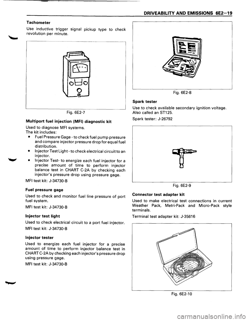
Tachometer
Use inductive trigger signal pickup type to check
revolution per minute.
Fig. 6E2-7
Multiport fuel injection (MFI) diagnostic kit
Used to diagnose MFI systems.
The kit
includes:
• Fuel
Pressure Gage-to check fuel pump pressure
and compare injector pressure
drop for equal fuel
distribution.
• Injector Test Light-to check electrical circuit to an
injector.
• Injector Test-to energize each fuel injector for a
precise
amount of time to perform injector
balance test in CHART C-2A by checking each
injector's pressure
drop using pressure gage.
MFI test kit: J-34730-8
Fuel pressure gage
Used to check and monitor fuel line pressure of port
fuel system.
MFI test kit: J-34730-8
Injector test light
Used to check electrical circuit to a port fuel injector.
MFI test kit: J-34730-8
Injector tester
Used to energize each fuel injector for a precise
amount of time to perform injector balance test in
CHART C-2A by checking each injector's pressure drop
using pressure gage.
MFI test kit: J-34730-8
DRIVEABILITY AND EMISSIONS 6E2-19
Fig. 6E2-8
Spark tester
Use to check available secondary ignition voltage.
Also called
an ST125.
Spark
tester: J-26792
Fig. 6E2-9
Connector test adapter kit
Used to make electrical test connections in current
Weather Pack, Metri-Pack and Micro-Pack
style
terminals.
Terminal test adapter kit: J-35616
Fig. 6E2-10