fuse diagram ISUZU TROOPER 1995 Workshop Manual
[x] Cancel search | Manufacturer: ISUZU, Model Year: 1995, Model line: TROOPER, Model: ISUZU TROOPER 1995Pages: 1928
Page 374 of 1928
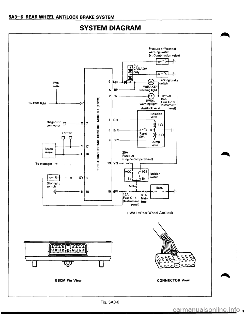
5A3-6 REAR WHEEL ANTILOCK BRAKE SYSTEM
SYSTEM DIAGRAM
4WD
switch
To 4WD
light -----11~-----lGY 3
Diagnostic Of------0 7 connector
For test
1-----11---+--y 17 Speed
sensor 1-----lt-----L
16
To
stoplight -----,
Stoplight switch
•IJI-----B 15
EBCM Pin View
i
&l ~ IU _, :;) Q
~ _, 0 a: .... z
8 IU ~ c( a: liD (.) z 0 a: 1-(.) IU _, IU
Pressure differential warning switch
(at Combination valve)
r-----+-<1 ~+II•
I•
6 LgB Parking brake _.-MI ____ ___,I'\.JI.Jr-, switch
5
BP -----'
2 w ------------~~._~
GR
4 BrR
9 BrY
20A Fuse F-9
RWAL 10
A •
1• h Fuse C-10
warnmg IQ t (Instrument
Antilock valve panel)
Isolation
valve
~ 4il .J o--1> ~
Reset ~1.5il
I
sw.
Dump valve
(Engine compartment)
13 YG -
82 81 switch
50 A
Batt.
10 GW + ,,
15A BOA Fuse C-14 Main (Instrument fuse panel)
RWAL=Rear Wheel Antilock
CONNECTOR View
Fig. 5A3-6
•
Page 722 of 1928
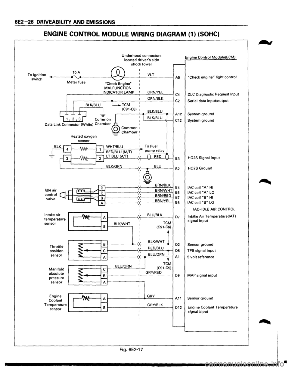
6E2-26 DRIVEABILITV AND EMISSIONS
ENGINE CONTROL MODULE WIRING DIAGRAM (1) (SOHC}
To ignition
switch 10 A
Meter fuse Underhood
connectors
located driver's side
shock tower
"Check Engine" MALFUNCTION
.-----------..:.:.1 N.:.:D:..:.IC=A~T~O:..:.R.:....=:.LA..::.M.:..::P:..___-,--___.:O:..:.R.:.:.N::.._IY.....:E:..:L=----1 c4
.------~~----~~O:..:R:..:N/~8~L=-=K--~ C 2
TCM
(C91-C8)
Engine Control Module(ECM)
"Check
engine" light control
DLC Diagnostic Request Input
Serial
data inpuVoutput
.--------f---+-....::...::;_;__=---_-1 A 12 System ground
Common
Data Link Connector (White) Chamber L.....::.=::....=..:=-=----+---1 C12 System ground
Intake air
temperature sensor
Throttle position
sensor
Manifold absolute pressure sensor
Engine
Coolant Temperature sensor Heated
oxygen
J-,.:..:W:.:..H.:..:T.:.:I8:..:L:.:U:......__ __ ....-To Fuel
RED/BLU (M/T)
1---=-'L T'-.!8~L:!:U'--l(.::::A/T!....!...!....) ---< f------lt+-~!,!..._'H---1 83
BRN/8LK
84
8RN/WHT 85
BRN/RED 87
8RN!YEL
BS
1---------~~~B~L~U~/8~L~K~--I 07
BLK/WHT
TCM
(C91-C6)
BLK/WHT 1------------4>---< t-----=~:..:.:..:_.:..:_ ....... -1 02
1-----------~ f----'-=-'-==--....-1 06
1-----------~ f--.-::..:=.=.:....=..c~-+--1 A 1
BLU/ORN
H02S Signal Input
H02S Ground
lAC coil "A" HI
lAC coil "A" LO
lAC coil "B" HI
lAC coil "B" LO
IAC=IDLE AIR CONTROL
Intake
Air Temperature(IAT)
signal input
Sensor ground
TPS signal input
5 volt reference
MAP
signal input
1---------'----...._.G:=.:..:.RY-=--------1 A 11 Sensor ground
1-------;---.:::G:..:R_;_YI:...::8:..:L::..:K:__---I 012 Engine Coolant Temperature
signal input
Fig. 6E2-17
•
Page 723 of 1928
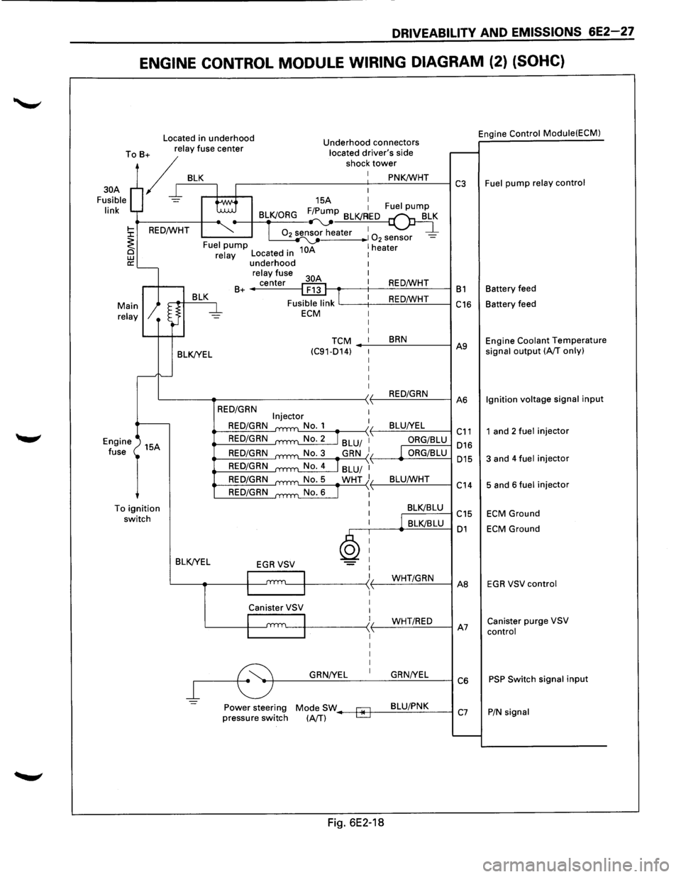
DRIVEABILITY AND EMISSIONS 6E2-27
ENGINE CONTROL MODULE WIRING DIAGRAM (2) (SOHC)
Located in underhood Engine Control
Module(ECM) Underhood connectors
To B+ relay fuse center located driver's side
/r BLK r----------s-ho-c-1-:-t-ow_:_::...:~.:..:K!Wc..:...:..:H:...:T.:..__---I C3 Fuel pump relay control
30A
Fusible
link
15A I F/P 1 Fuel pump BLK/ORG ~~
02 sensor heater 1 1 0 -2 sensor -10A 1 heater Fuel pump
BLK/YEL
relay Located in underhood relay fuse
center
B+ ------1
I
REO/WHT t---.-----t--:..:.::::..=.!...:...:..:..:...:_.:..._--1 B 1 Battery feed
REO/WHT
'-----t--..:.:..::-=:!....:c.:.:...:.-=-------1 C16 Battery feed
TCM BRN (C91-014) -_.:..._--=..:..:..:...:----1 A9 Engine Coolant Temperature signal output (A/T only)
L----~-----------~~-.:..:R.:::EO~/~G~R~N_:_--IA6 Ignition
voltage signal input
Engine
fuse 15A
To
ignition switch BLK/YEL
=
REO/GRN
REO/GRN
REO/GRN
REO/GRN
REO/GRN
REO/GRN
REO/GRN
ORG/BLU 016
ORG/BLU 015
L:...:..::..:-=---.....-:..:.:....:...!._{ L_B::..:L:..:U:c..IW:..:..:...:.HT_:__--l c " 14
BLK/BLU C15
,--.----<.._.:::B.:::LKI=B.::.LU=---1 01
GRN/YEL GRN/YEL
~--~~~~--~~~~--~C6
Power steering Mode SW--+*-f--=-8=-LU~/.:..P.:..:N~K:___---l pressure switch (A/T) C7
Fig. 6E2-18
1 and 2 fuel injector
3 and 4 fuel injector
5 and 6 fuel injector
ECM Ground
ECM Ground
EGR VSV control
Canister purge VSV
control
PSP Switch signal input
P/N signal
Page 724 of 1928
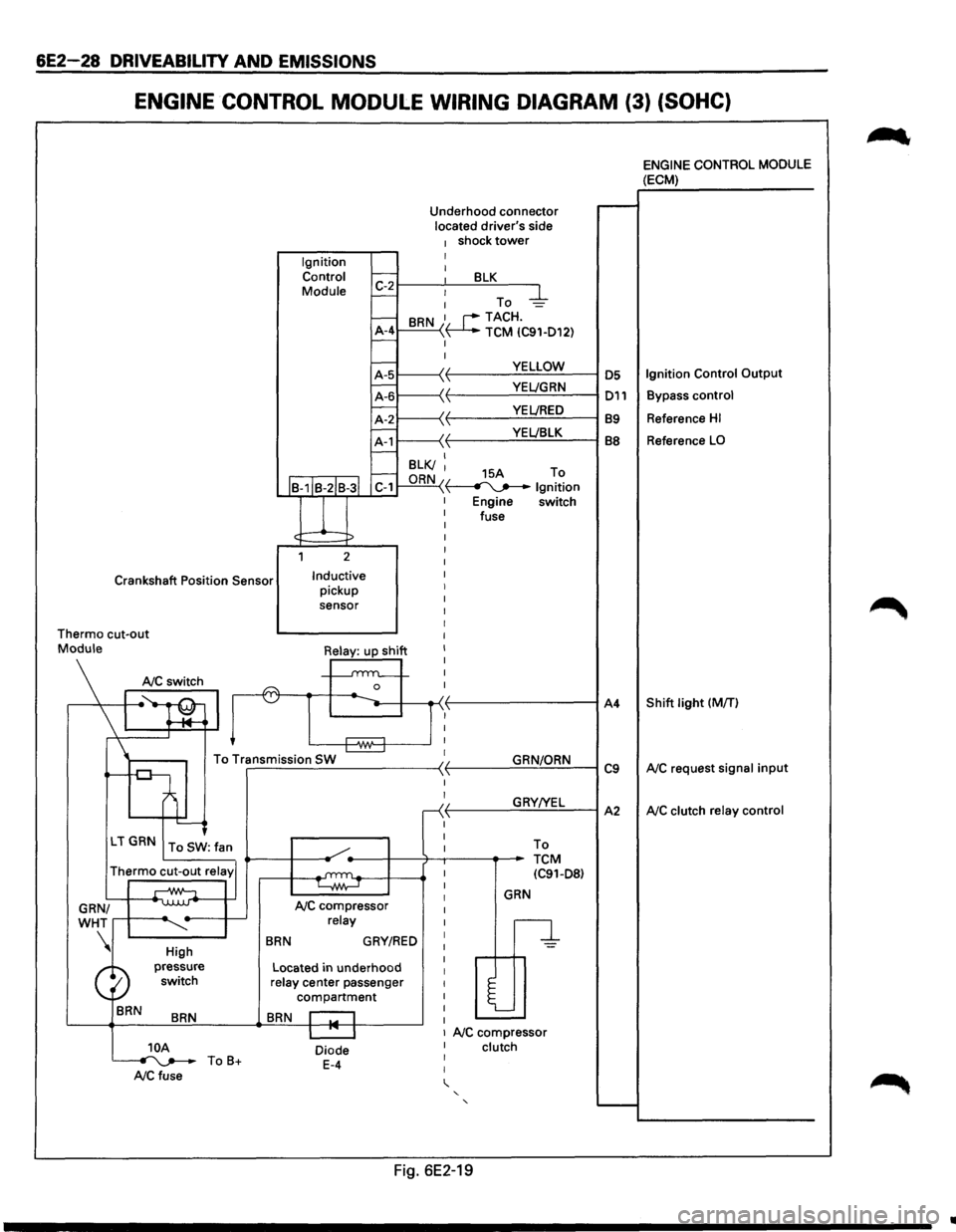
6E2-28 DRIVEABILITV AND EMISSIONS
ENGINE CONTROL MODULE WIRING DIAGRAM (3) (SOHC)
Ignition Control
Module Underhood
connector
located driver's side
1 shock tower I I 1:-2~--~~--~B~L~K~--~
- : To -4-
-BRN 1. r--TACH.
A-4 ~ TCM IC91-D12) -I
I
YELLOW
·~ YEL!GRN \ VEL/RED YEL!BLK
I--B-1IB-2IB-3l C-1
l
1 2
Crankshaft Position Sensor Inductive pickup
sensor I
I
I
I
Thermo cut-out I
I
I
I
I
n I
Mo\\I•Silj ~~
To Transmission SW ~ r-------------------~ -
'---<
LT GRN To SW: fan
Thermo cut-out relay'
GRN/
WHT
....--+-----~
BRN
High
pressure switch
BRN
NC compressor relay
BRN GRY/RED
Located in underhood relay center passenger
compartment
BRN r::-1
I
I
r
I
I
I
I
I
I
I
I
I
I
I
I
I
I
GRN/ORN
GRY!YEL To
TCM IC91-D8)
GRN
n
l
I I 1 NC compressor 10A ~ToB+ NCfuse
Diode E-4
I clutch I
I
' ' '
Fig. 6E2-19
A4
C9
A2
~
ENGINE CONTROL MODULE (ECM)
Reference HI
Reference LO
Shift light (MfT)
NC request signal input
NC clutch relay control
..
Page 725 of 1928
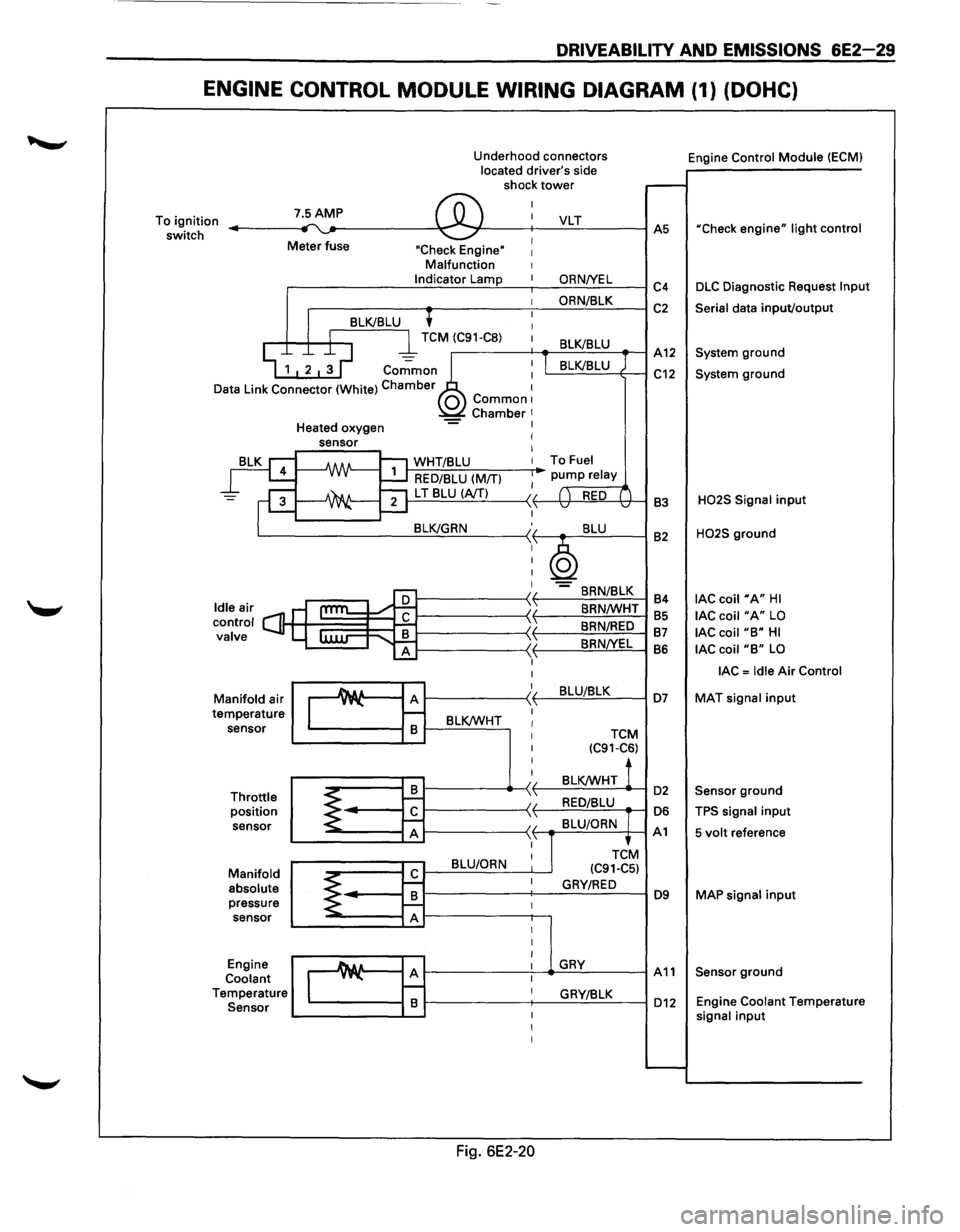
DRIVEABILITY AND EMISSIONS 6E2-29
ENGINE CONTROL MODULE WIRING DIAGRAM (1) (DOHC)
Underhood connectors
located driver's side
shock
tower
To ignition
switch 7.5AMP ,.... ~ ®
I
I
Meter fuse I "Check Engine" I Malfunction I Indicator Lamp I
I
'
I 8LK/8LU I
D
I l TCM (C91-C8) 1
~ 1 2 ~ ~ co.;;mo~~ : ata Link Connector (White) Chamber 1 0 Common1 Chamber 1 Heated oxygen -= I
rg
=F
leair s ontrol C] alve
ld c v
M
te anifold
air
mperature sensor
Throttle position sensor
Manifold absolute pressure sensor
Engine
Coolant
T emperature
Sensor
sensor I
I
-A/IN-1:'1 WHT/8LU I
~ RED/8LU (M/TI I
~ ""21 L T 8LU (A/TI II ....::....1 ,1,
8LK/GRN :,
I
I
I
I
cam l:
I
I
Au A )I y"-\1 r--
8 8LK/WHT I I
I
I
I
8 ~ 1--II
~ r£ \ 'I A ,1,
8LU/ORN I
r£ ~ I
8 ~ f--I A I
I
I
_A& a A I y"-I r--I 8 I
I
I
Fig. 6E2-20
VLT
ORNNEL
ORN/8LK
8LK/8LU
I 8LK/8LU
To Fuel
pump relay
( ) RED ( v v
8LU
~ -8RN/8LK
8RN/WHT
8RN/RED
8RNNEL
8LU/8LK
TCM (C91-C6)
8LK/WHT !
RED/8LU
8LU/ORN
TCtM
(C91-C5)
GRY/RED
GRY
GRY/8LK Engine
Control
Module (ECMI
.-----
AS "Check engine" light control
C4 DLC Diagnostic Request lnpu
C2 Serial data input/output
A12 System ground
C12 System ground
83
H02S Signal input
82 H02S ground
84
lAC coil "A" HI
85 lAC coil "A" LO
87 lAC coil "8" HI
86 lAC coil "8" LO
lAC = Idle Air Control
D7 MAT signal input
D2 Sensor ground
D6 TPS signal input
A1 5 volt reference
D9 MAP signal input
A11 Sensor ground
D12 Engine Coolant Temperatur e signal input
......__
Page 726 of 1928
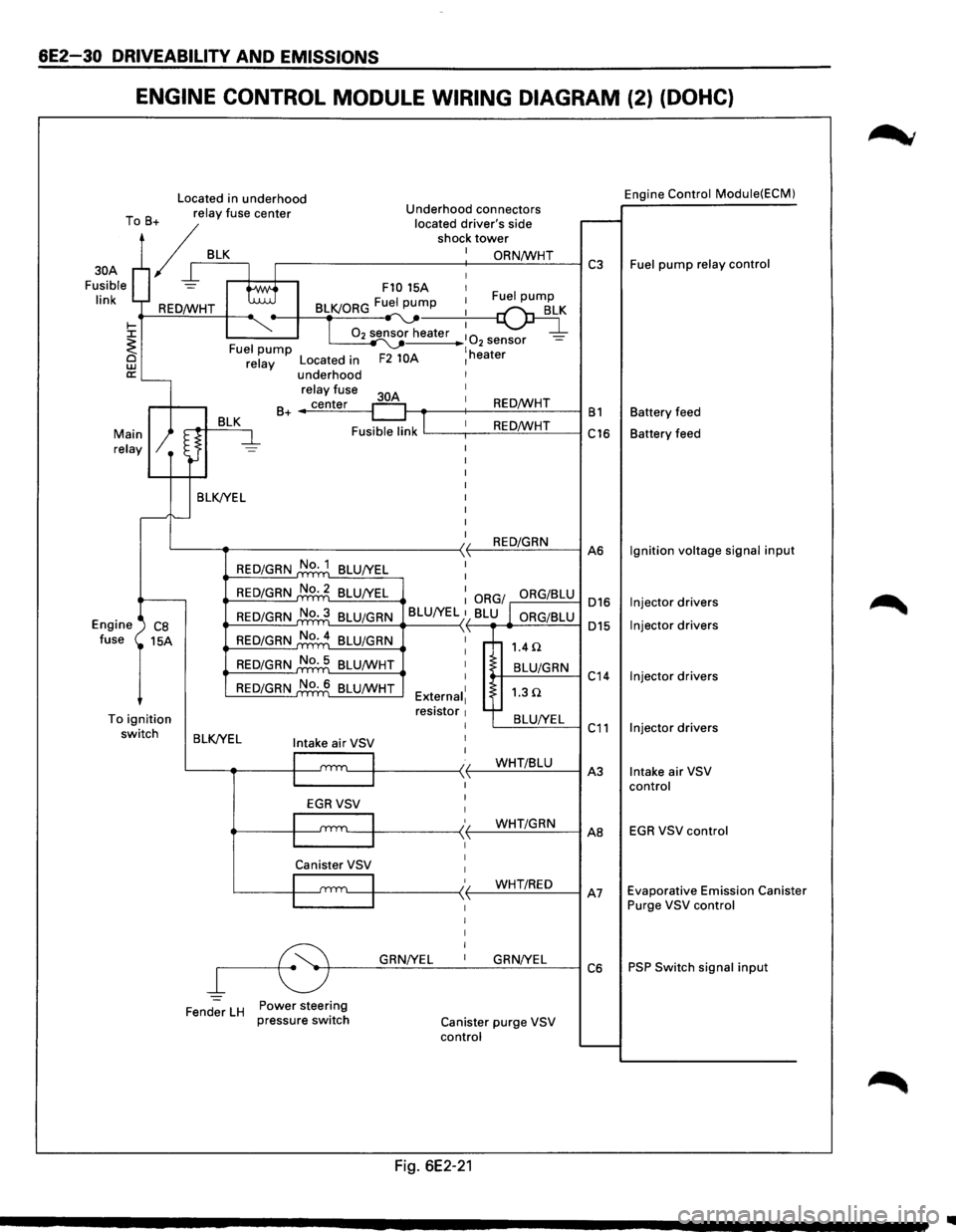
6E2-30 DRIVEABILITY AND EMISSIONS
ENGINE CONTROL MODULE WIRING DIAGRAM (2) (DOHC)
Located in underhood Engine Control Module(ECM)
T B relay
fuse center Underhood connectors
o + located
driver's side r--. / shock tower
/ I BLK.---+-I_: ~==-----------+-: __ O_R_N...:./W_H_T_--1 C3 Fuel pump relay control
Fusible
= tti F10 15A 1
30A
I' k I 1 Fuel pump In REO/WHT BLK/ORG Fu:.._pu~
~ ~-T 02 sensor heater :
0 _ ~ I ~ 2 sensor -<. Fuel pump ~ lh @ relay Located in F2 10A 1 eater
a:'---underhood
relay fuse I
BLK 30A
1 B+ _..;c:..::ec:..:n-=.:te:.:..r_-1 REO/WHT B1 Battery
feed
Fusible link
lL---,--1 _ _:.:R:.=E-==O'-'fW:..:..:....:H-=-T---i C16 Battery feed Main relay
BLK/YEL I
I
I
I
I
I
I
L---~--------------<)1 REO/GRN ,1, A6
Engine ') CB fuse 15A
To ignition switch
REO/GRN No. 1
BLU/YEL I
REO/GRN No.2 BLU/YEL : ORG/ ORG/BLU 016
015
REO/GRN No.3 BLU/GRN
BLU/YEL }1 BLU l ORG/BLU L....::-=-=.:...=.:._.._ __ -<
REO/GRN No.4
BLU/GRN \'
REO/GRN No. 5
BLU/WHT
REO/GRN No. 6 BLU/WHT I
I
External1 resistor 1 I
1.4 n
t-+--B_L-'U/_G_R_N--1 C
14
1.3Q
'---=B:..::L:..::U_:_IY;_:E:.:L~ C 11 BLK/YEL Intake air VSV I
I
l
I I t.__-1~-----< t--...:...W:..:.H.:....:.T.:...::/B:..::Lc::.U_-1 A
3
I
I
I
EGRVSV
'---111 ____ -<' (-_...:...W.:....:.H.:....:.T.:...c/G=-R_N_-1 AB
Canister VSV 1
I 1
/ WHT/REO I '---1~-----<,f--,--"------1 A7 ~------~ I I I I
~r---G~RN~/Y~E_L __ 1 __ G~R_N...:.!Y_EL_~ C 6
Fender
LH Power steering
pressure switch Canister purge VSV
control
Fig. 6E2-21
Ignition voltage signal input
Injector drivers
Injector drivers
Injector drivers
Injector drivers
Intake air VSV
control
EGR VSV control
Evaporative Emission Canister
Purge VSV control
PSP Switch signal input
1111
Page 727 of 1928
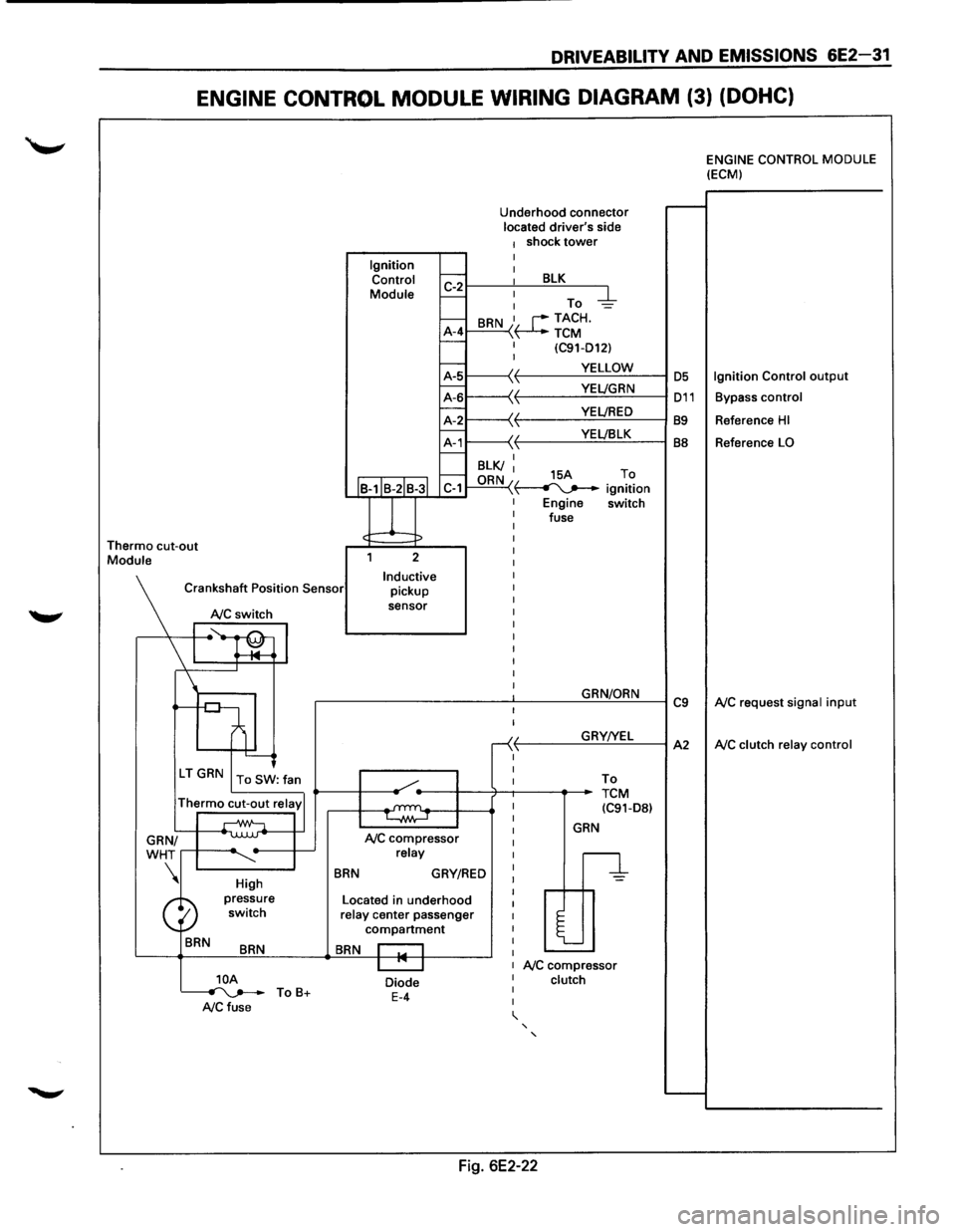
DRIVEABILITV AND EMISSIONS 6E2-31
ENGINE CONTROL MODULE WIRING DIAGRAM (3) (DOHC)
Thermo cut-out Module Ignition
Control
Module
J
Underhood connector located driver's side 1 shock tower I
~r---~: ___ B~L=K~--~
I-: To -d::-1--A-4 I-
BRN I, r--TACH. \~TCM I (C91-D12) I
~1-----\(. f-------...:.Y.=.E:::LL:.:O:..:W:..:._--1 OS
~L-----'~
11---\-{' t----Y:..::E~LJ:..:::B.:::LK~--l BB f.---I BLK/ I f.---ORN 15A To C-1 "\~ ignition
Engine switch
fuse
2
Inductive pickup
sensor
Crankshaft
Position Sensor
NC switch
I ~~ l '--------J
\'r-----.
High
BRN
BRN
]_OA ~ ToB+ A/C fuse
BRN
NC compressor relay
GRY/RED
Located in underhood relay center passenger compartment
BRN I I I "' I
Diode E-4
I
I
-<( ,1,
I
I
GRN/ORN
GRY!YEL
To
TCM (C91-D8l
GRN
n
l
NC compressor clutch
' '
Fig. 6E2-22
C9
A2
ENGINE CONTROL MODULE (ECM)
Ignition Control output
Bypass control
Reference HI
Reference LO
NC request signal input
NC clutch relay control
Page 1191 of 1928

CHASSIS ELECTRICAL 8-1
·SECTION 8
CHASSIS ELECTRICAL
'\f CAUTION: .
When fasteners are removed, always reinstall them at the same location from which they were removed.
If a fastener needs to be replaced, use the correct part number fastener for that application. If the correct
part number fastener is not
available, a fastener of equal size and strength (or stronger) may be used.
Fasteners that are not reused, and those requiring thread
locking compound, will be called out. The correct
torque
values must be used when installing fasteners that require it. If the above conditions are not
followed, parts or system damage could result.
CONTENTS
General Information .................................... 8-2
Notes for Working on Electrical
Items .................................................... 8-2
Symbols and Abbreviations ................. 8-8
Symbols ............................................ 8-8
Abbreviations ................................... 8-9
Parts for Electrical Circuit ..................... 8-10
Wiring ............................................... 8-10
Fuse .................................................. 8-11
Fusible Link ....................................... 8-12
Circuit Breaker ................................... 8-12
Relay ................................................. 8-12
Relay Specifications and
Configurations ................................ 8-13
Diode ................................................. 8-14
Connector ......................................... 8-15
Reading the Circuit Diagram ................ 8-17
Main Data and Specifications .................... 8-19
Bulb Specifications ................................ 8-19
Fuse,
Fusible Link and
Circuit Breaker Location ..................... 8-21
Fuse
Block Circuit .................................. 8-22
Reference Table of Fuse, Fusible
Link and Circuit Breaker ..................... 8-23
Relay Location ....................................... 8-27
Diode Location .......................................
8-28
Grounding Point .................................... 8-29
Reference Table ................................ 8-29
Location ............................................ 8-31
Cable Harness Routing .......................... 8-34
System Repair .............................................. 8-38
Start and Charging ................................ 8-38
Engine Control Module
(ECM) ................................................... 8-47
Headlight and Fog Light ........................ 8-58
Front Side Marker Light, Parking Light,
Taillight, License Plate Light and
Illumination Light .............................. 8-76
Stoplight and Rear Defogger .............. 8-92
Turn Signal Light, Hazard
Warning
Light, Cornering Light,
Backup
Light and Horn ..................... 8-106
Dome Light, Luggage room Light,
Courtesy Light, Map Light,
Seat Belt Switch and
Warning Buzzer ................................. 8-128
Power Door Lock ................................. 8-142
Power
Window .................................... 8-156
Cruise
Control ...................................... 8-172
Anti-Lock Brake
System (ABS) ........... 8-178
Rear
Wheel Anti-Lock Brake
System (RWAL) ................................. 8-185
Transmission
Control Module
(TCM) ................................................. 8-192
A/T Shift Lock ...................................... 8-200
Windshield
Wiper/Washer and
Rear
Wiper/Washer .......................... 8-205
Headlight wiper /washer ..................... 8-232
Audio, Auto Antenna,
Cigarette
Lighter and digital clock ... 8-246
Power Door Mirror ............................... 8-254
Anti-theft System ................................ 8-270
Meter and Warning/Indicator Light ... 8-288
A/T Shift Indicator ............................... 8-336
Heater and
Air Conditioning ............... 8-340
Sun
Roof ............................................... 8-346
Power Seat ........................................... 8-360
Seat
Heater .......................................... 8-37 4
Supplemental Restraint
System (SRS) -AIR BAG ................... 8-382
Page 1192 of 1928
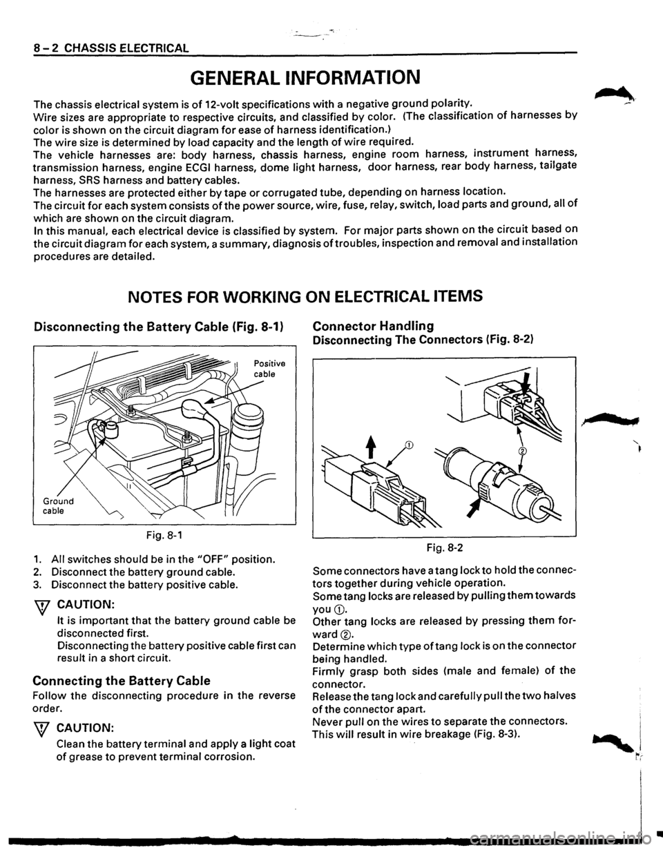
-·*; ~---
8-2 CHASSIS ELECTRICAL
GENERAL INFORMATION
The chassis electrical system is of 12-volt specifications with a negative ground polarity.
Wire sizes are appropriate
to respective circuits, and classified by color. (The classification of harnesses by
color is shown on the circuit diagram for ease of harness identification.)
The
wire size is determined by load capacity and the length of wire required.
The
vehicle harnesses are: body harness, chassis harness, engine room harness, instrument harness,
transmission harness, engine
ECGI harness, dome light harness, door harness, rear body harness, tailgate
harness,
SRS harness and battery cables.
The harnesses are protected either
by tape or corrugated tube, depending on harness location.
The circuit
for each system consists of the power source, wire, fuse, relay, switch, load parts and ground, all of
which are shown on the circuit diagram.
In this manual, each electrical device is classified by system. For major parts shown on the circuit based on
the circuit diagram
for each system, a summary, diagnosis oftroubles, inspection and removal and installation
procedures are detailed.
NOTES FOR WORKING ON ELECTRICAL ITEMS
Disconnecting the Battery Cable (Fig. 8-1)
Ground cable
Fig. 8-1
1. All switches should be in the "OFF" position.
2. Disconnect the battery ground cable.
3. Disconnect the battery positive cable.
W CAUTION:
It is important that the battery ground cable be
disconnected first.
Disconnecting the battery positive cable first can
result in a short circuit.
Connecting the Battery Cable
Follow the disconnecting procedure in the reverse
order.
\V CAUTION:
Clean the battery terminal and apply a light coat
of grease to prevent terminal corrosion.
Connector Handling
Disconnecting The Connectors (Fig. 8-2)
Fig. 8-2
Some connectors have a tang lock to hold the connec
tors together during vehicle operation.
Some tang locks are released by pulling them towards
you
G).
Other tang locks are released by pressing them for
ward®.
Determine which type oftang lock is on the connector
being handled.
Firmly grasp both sides (male and female)
of the
connector. Release the tang lock and carefully pull the
two halves
of the connector apart.
Never pull on the wires
to separate the connectors.
This
will result in wire breakage (Fig. 8-3).
.,
..
Page 1207 of 1928
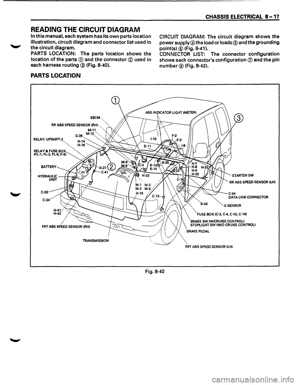
READING THE CIRCUIT DIAGRAM
In this manual, each system has its own parts location
illustration,
circuit diagram and connector list used in
the circuit diagram.
PARTS LOCATION: The parts location shows the
location of the parts CD and the connector® used in
each harness routing ® (fig. 8-40).
PARTS LOCATION
EBCM-,
RR ABS SPEED SENSOR (RHI "',~ M-11 ,,
C-39 M-12~'-, RELAY: UPSHIFT-2 ~
CHASSIS ELECTRICAL 8-17
CIRCUIT DIAGRAM: The circuit diagram shows the
powersupply@the load or loads® and the grounding
point(s)
® (Fig. 8-41 ).
CONNECTOR LIST: The connector configuration
shows
each connector's configuration (J) and the pin
number® (Fig. 8-42).
RELAY & FUSE BO~"'
7
~<-:;;;:~:~:_::0:;;::::'=l-\,.-..:._::::;;,...6
IFL-1, FL-2, FL-6, F-91 , "" ;;~~~~~~~;g~~k~
C-33
C-34
Fig. 8-40
STARTERSW
RR ABS SPEED SENSOR ILHI
C-94 DATA LINK CONNECTOR
GSENSOR
FUSE BOX IC-3, C-4, C-10, C-141
BRAKE SW IW/CRUISE CONTROL! STOPLIGHT SW (W/0 CRUISE CONTROL!
FRT ABS SPEED SENSOR ILHI