length ISUZU TROOPER 1995 Workshop Manual
[x] Cancel search | Manufacturer: ISUZU, Model Year: 1995, Model line: TROOPER, Model: ISUZU TROOPER 1995Pages: 1928
Page 137 of 1928
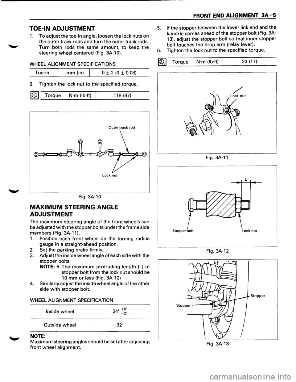
TOE-IN ADJUSTMENT
1. To adjust the toe-in angle, loosen the lock nuts on
the outer track rods and turn the outer track rods.
Turn both rods the same amount, to keep the
steering
wheel centered (Fig. 3A-1 0).
WHEEL ALIGNMENT SPECIFICATIONS
Toe-in mm (in) I 0 ± 2 (0 ± 0.08)
2. Tighten the lock nut to the specified torque.
~~~ Torque N·m (lb·ft) 118 (87)
Outer track rod
Lock nut
Fig. 3A-10
MAXIMUM STEERING ANGLE
ADJUSTMENT
The maximum steering angle of the front wheels can
be adjusted
with the stopper bolts under the frame side
members (Fig. 3A-11 ).
1. Position each front wheel on the turning radius
gauge in a straight-ahead position.
2. Set the parking brake firmly.
3. Adjust the inside wheel angle of each side with the
stopper
bolts.
NOTE: • The maximum protruding length (L) of
stopper bolt from the lock nut should be
10 mm or less (Fig. 3A-12)
4. Similarly adjust the inside wheel angle of the other
side
with stopper bolt.
WHEEL ALIGNMENT SPECIFICATION
Inside wheel
34° ~~:
Outside wheel 32°
NOTE:
Maximum steering angles should be set after adjusting
front wheel alignment.
FRONT END ALIGNMENT 3A-5
5. If the stopper between the lower link end and the
knuckle comes ahead of the stopper bolt (Fig. 3A-
13), adjust the stopper
bolt so that inner stopper
bolt touches the drop arm (relay lever).
6. Tighten the lock nut to the specified torque.
~~~ Torque N·m (lb·ft) 23 (17)
Fig. 3A-11
L
Stopper bolt Lock nut
Fig. 3A-12
Stopper
Fig. 3A-13
Page 161 of 1928
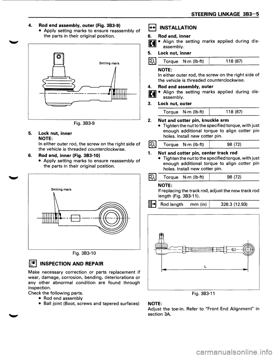
4. Rod end assembly, outer (Fig. 383-9)
• Apply setting marks to ensure reassembly of
the parts in their original position.
Setting mark
Fig. 3B3-9
5. Lock nut, inner
NOTE:
6.
In either outer rod, the screw on the right side of
the vehicle is threaded counterclockwise.
Rod end, inner (Fig. 383-1 O)
• Apply setting marks to ensure reassembly of
the parts in their original position.
Setting mark
--B--
Fig. 3B3-10
(1!] INSPECTION AND REPAIR
Make necessary correction or parts replacement if
wear, damage, corrosion, bending, deteriorations or
any other abnormal condition are found through
inspection.
Check the
following parts.
• Rod end assembly
STEERING LINKAGE 383-5
1••1 INSTALLATION
6. Rod end, inner
IP.il • Align the setting marks applied during dis-
~ assembly.
5. Lock nut, inner
~~~ Torque N·m (lb·ft) 118 (87)
NOTE:
In either outer rod, the screw on the right side of
the vehicle is threaded counterclockwise.
4. Rod end assembly, outer
IP.il • Align the setting marks applied during dis-
~ assembly.
3. Lock nut, outer
Torque N·m (lb·ft) 118 (87)
2. Nut and cotter pin, knuckle arm
• Tighten the nutto the specified torque, with just
enough additional torque to align cotter pin
holes. Install new cotter pin.
~~~ Torque N·m (lb·ft) ___ ______._ ___ _ 98 (72)
1. Nut and cotter pin, center track rod
• Tighten the nutto the specified torque, with just
enough additional torque to align cotter pin
holes. Install new cotter pin.
~~~ Torque N·m (lb·ft) 98 (72)
NOTE:
If replacing
the track rod, adjust the new track rod
length (Fig. 3B3-11).
I~EI Rod length mm (in) I 328.3 (12.93)
L
Fig. 3B3-11
• Ball joint (Boot, screws and tapered surfaces) NOTE:
Adjust the toe-in. Refer to "Front End Alignment" in
section 3A.
Page 184 of 1928
3C-20 FRONT SUSPENSION
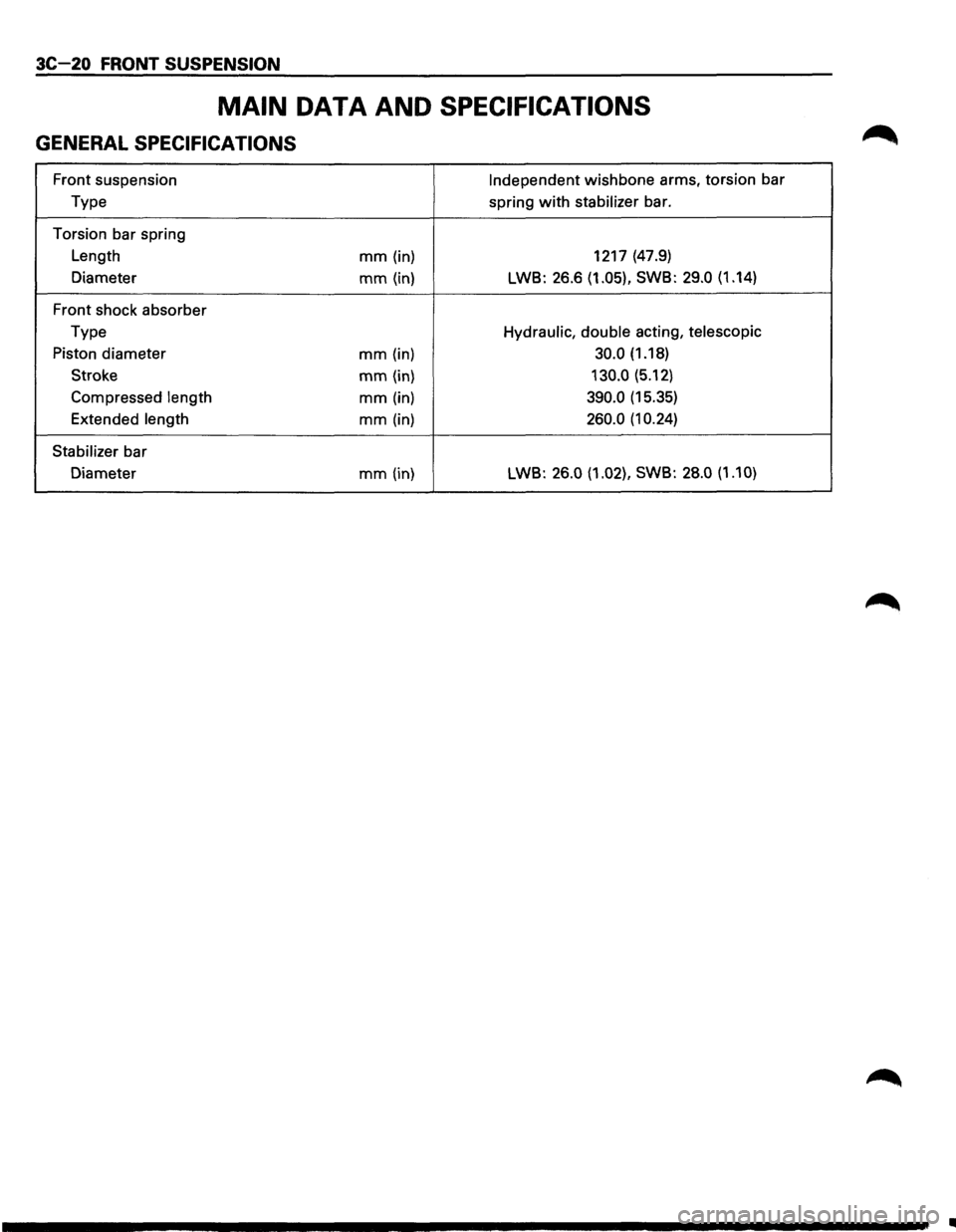
MAIN DATA AND SPECIFICATIONS
GENERAL SPECIFICATIONS
Front suspension Independent wishbone arms, torsion bar
Type spring
with stabilizer bar.
Torsion bar spring
Length
mm (in) 1217
(47.9)
Diameter
mm (in) LWB: 26.6 (1.05), SWB: 29.0 (1.14)
Front shock absorber
Type
Hydraulic, double acting, telescopic
Piston diameter mm (in) 30.0 (1.18)
Stroke
mm (in) 130.0 (5.12)
Compressed
length mm (in) 390.0 (15.35)
Extended
length mm (in) 260.0 (1 0.24)
Stabilizer
bar
Diameter
mm (in) LWB: 26.0 (1.02),
SWB: 28.0 (1.10)
•
Page 189 of 1928
REAR SUSPENSION 30-3
ON-VEHICLE SERVICE
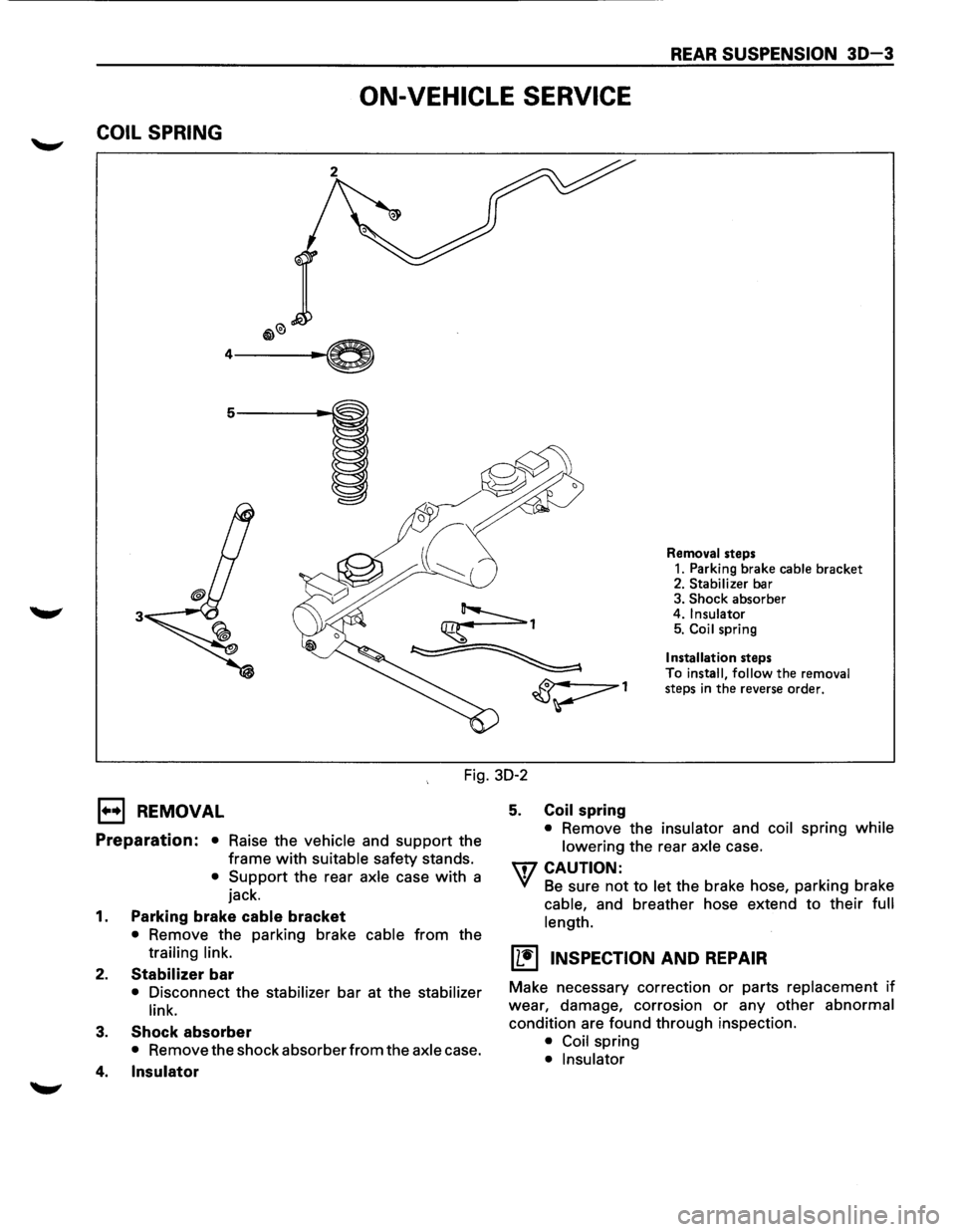
COIL SPRING
3
Removal steps
1. Parking brake cable bracket 2. Stabilizer bar
3. Shock absorber
4. Insulator 5. Coil spring
Installation steps
To install,
follow the removal
steps in the reverse order.
Fig. 30-2
E) REMOVAL
Preparation: • Raise the vehicle and support the
frame
with suitable safety stands.
• Support the rear axle case with a
jack.
1. Parking brake cable bracket
• Remove the parking brake cable from the
trailing link.
2. Stabilizer bar
• Disconnect the stabilizer bar at the stabilizer
link.
3. Shock absorber
• Remove the shock absorber from the axle case.
4. Insulator
5. Coil spring
• Remove the insulator and coil spring while
lowering
the rear axle case.
U7 CAUTION:
VI Be sure not to let the brake hose, parking brake
cable, and breather hose extend to their full
length.
(L!] INSPECTION AND REPAIR
Make necessary correction or parts replacement if
wear, damage, corrosion or any other abnormal
condition are found through inspection.
• Coil spring
• Insulator
Page 198 of 1928
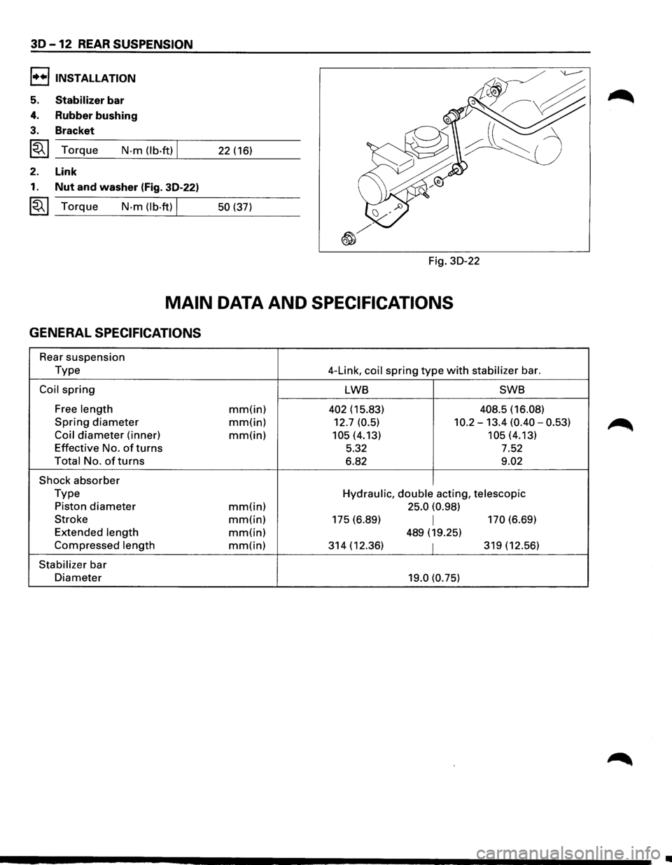
3D -12 REAR SUSPENSION
l+•liNSTALLATION
5. Stabilizer bar
4. Rubber bushing
3. Bracket
~~~ Torque N·m (lb.ft) I 22 (16)
2. Link
1. Nut and washer (Fig. 30-22)
~~~ Torque N-m (lb·ft) I 50 (37)
Fig.
30-22
MAIN DATA AND SPECIFICATIONS
GENERAL SPECIFICATIONS
Rear suspension
Type 4-Link, coil spring type with stabilizer bar.
Coil spring LWB SWB
Free
length mm(in) 402 (15.83) 408.5 (16.08)
Spring diameter mm(in) 12.7 (0.5) 10.2-13.4 (0.40-0.53)
Coil diameter (inner) mm(in) 105 (4.13) 105(4.13)
Effective No.
of turns 5.32 7.52
Total No. of turns 6.82 9.02
Shock absorber
Type Hydraulic, double acting, telescopic
Piston diameter mm(in) 25.0
(0.98)
Stroke
mm(in) 175 (6.89) I 170 (6.69)
Extended
length mm(in) 489 (19.25)
Compressed length mm(in) 314 (12.36) I 319 (12.56)
Stabilizer bar
Diameter 19.0 (0.75)
•
Page 240 of 1928
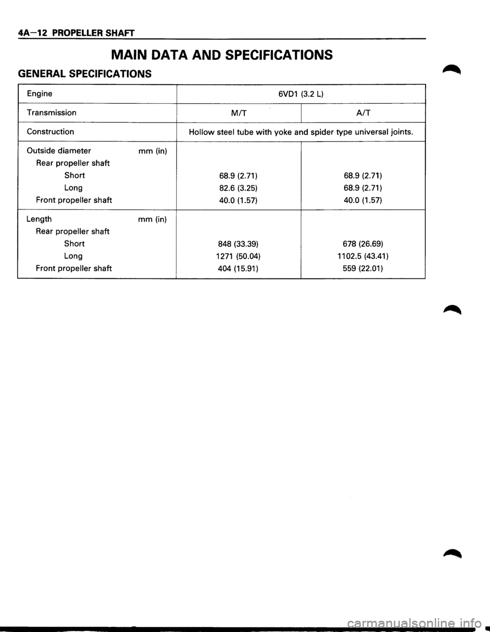
4A-12 PROPELLER SHAFT
MAIN DATA AND SPECIFICATIONS
GENERAL SPECIFICATIONS
Engine 6VD1 (3.2 L)
Transmission MIT A/T
Construction Hollow steel tube with yoke and spider type universal joints.
Outside diameter mm (in)
Rear
propeller shaft
Short 68.9 (2.71) 68.9
(2.71)
Long 82.6 (3.25) 68.9
(2.71)
Front
propeller shaft 40.0 (1.57) 40.0 (1.57)
Length
mm (in)
Rear
propeller shaft
Short 848 (33.39) 678
(26.69)
Long
1271 (50.04) 11 02.5 (43.41)
Front
propeller shaft 404 (15.91) 559 (22.01)
..
Page 272 of 1928
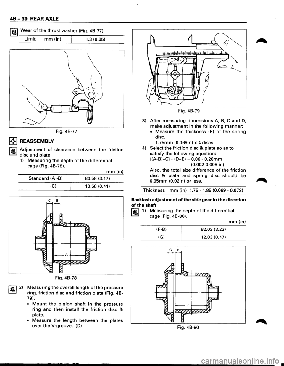
48-30 REAR AXLE
lfil!.l Wear of the thrust washer (Fig. 48-77)
Limit mm (in) I 1.3 (0.05)
Fig. 48-77
l•!•l REASSEMBLY
l"fll Adjustment of clearance between the friction
~ disc and plate
1) Measuring the depth of the differential
cage (Fig. 48-78).
~ 2)
mm(in)
Standard (A -8) 80.58 (3.17)
(C) 10.58 (0.41)
c 8
Fig. 48-78
Measuring the overall length ofthe pressure
ring,
friction disc and friction plate (Fig. 48-
79).
• Mount the pinion shaft in the pressure
ring and then install the friction disc &
plate.
•
Measure the length between the plates
over the V-groove. (D) Fig.
48-79
3) After measuring dimensions A, 8, C and D,
make adjustment in the following manner:
• Measure the thickness (E) of the spring
disc.
1.75mm (0.069in) x 4 discs
4) Select the friction disc & plate so as to
satisfy the following equation:
{(A-8)+C}-(D+E) = 0.06-0.20mm
(0.002-0.008 in)
Also, the total size difference of the friction
disc & plate and spring disc should be
0.05mm (0.02in) or less.
Thickness mm (in) 11.75-1.85 (0.069-0.073)
Backlash
adjustment of the side gear in the direction
of the shaft
lfil!.l1) Measuring the depth of the differential
cage (Fig. 48-80).
mm(in)
(F-8) 82.03 (3.23)
(G) 12.03 (0.47)
G 8
Fig. 48-80
Page 322 of 1928
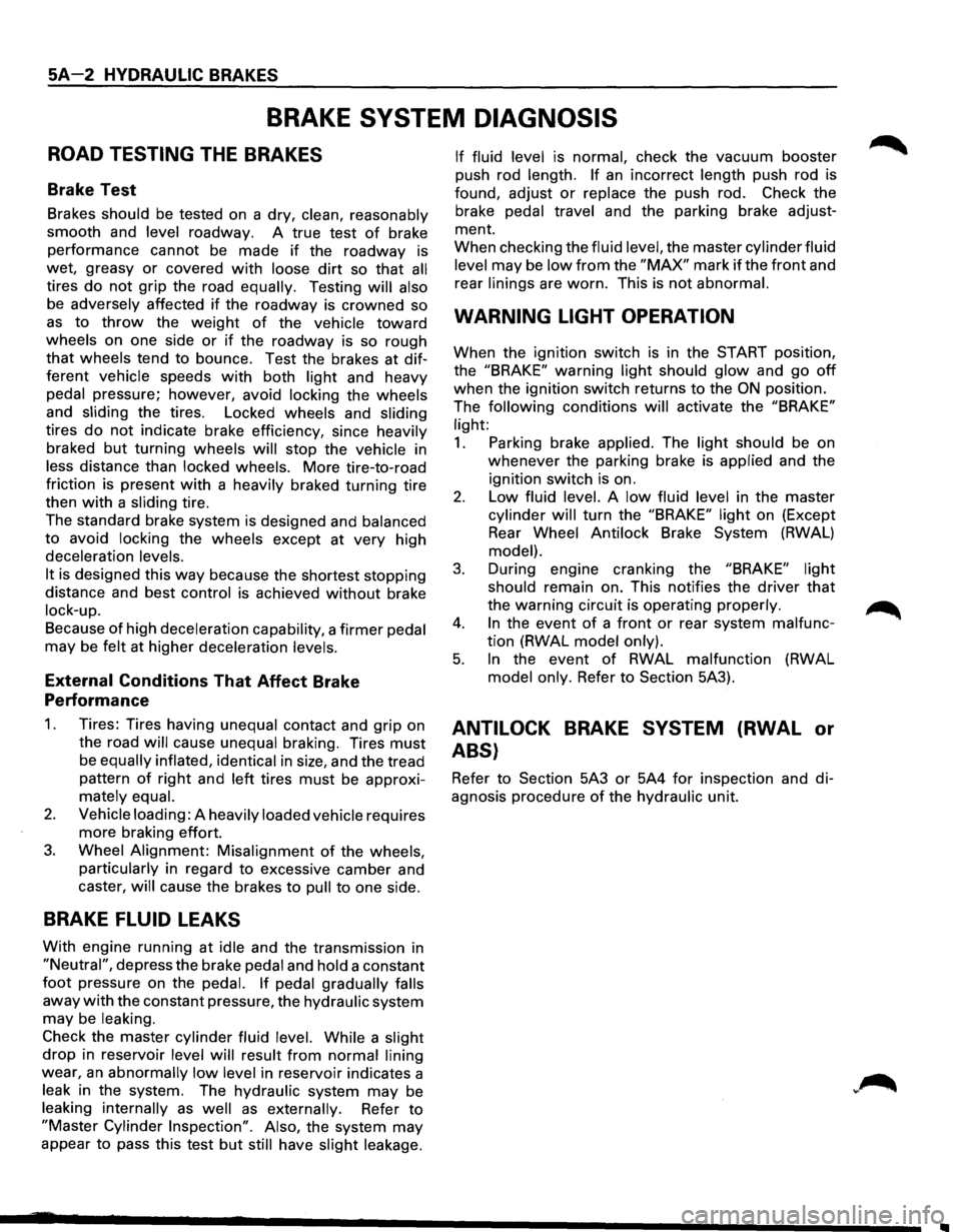
SA-2 HYDRAULIC BRAKES
BRAKE SYSTEM DIAGNOSIS
ROAD TESTING THE BRAKES
Brake Test
Brakes should be tested on a dry, clean, reasonably
smooth and
level roadway. A true test of brake
performance cannot be made
if the roadway is
wet, greasy
or covered with loose dirt so that all
tires do not grip the road equally. Testing will also
be adversely affected if the roadway is crowned so
as to throw the weight of the vehicle toward
wheels on one side or if the roadway is so rough
that wheels tend to bounce. Test the brakes at dif
ferent vehicle speeds with both light and heavy
pedal pressure; however, avoid locking the wheels
and sliding the tires. Locked wheels and sliding
tires do not indicate brake efficiency, since heavily
braked but turning wheels will stop the vehicle in
less distance than locked wheels. More tire-to-road
friction is present
with a heavily braked turning tire
then
with a sliding tire.
The standard brake system is designed and
balanced
to avoid locking the wheels except at very high
deceleration
levels.
It
is designed this way because the shortest stopping
distance and best
control is achieved without brake
lock-up.
Because of high deceleration capability, a firmer pedal
may be felt at higher deceleration levels.
External Conditions That Affect Brake
Performance
1.
2.
3.
Tires: Tires having unequal contact and grip on
the road
will cause unequal braking. Tires must
be equally inflated, identical in size, and the tread
pattern
of right and left tires must be approxi
mately equal.
Vehicle loading:
A heavily loaded vehicle requires
more braking effort.
Wheel Alignment: Misalignment of the wheels,
particularly
in regard to excessive camber and
caster,
will cause the brakes to pull to one side.
BRAKE FLUID LEAKS
With engine running at idle and the transmission in
"Neutral", depress the brake pedal and hold a constant
foot pressure on the pedal. If pedal gradually falls
away with the constant pressure, the hydraulic system
may be leaking.
Check the master cylinder fluid level. While a slight
drop in reservoir level will result from normal lining
wear, an abnormally low level in reservoir indicates a
leak in the system. The hydraulic system may be
leaking internally as well as externally. Refer to
"Master Cylinder Inspection". Also, the system may
appear
to pass this test but still have slight leakage. If
fluid level
is normal, check the vacuum booster
push rod
length. If an incorrect length push rod is
found, adjust
or replace the push rod. Check the
brake
pedal travel and the parking brake adjust
ment.
When checking the
fluid level, the master cylinder fluid
level
may be low from the "MAX" mark if the front and
rear
linings are worn. This is not abnormal.
WARNING LIGHT OPERATION
When the ignition switch is in the START position,
the
"BRAKE" warning light should glow and go off
when the ignition switch returns to the ON position.
The
following conditions will activate the "BRAKE"
light:
1. Parking brake applied. The light should be on
whenever the parking brake is applied and the
ignition switch is on.
2. Low fluid level. A low fluid level in the master
cylinder will turn the "BRAKE" light on (Except
Rear
Wheel Antilock Brake System (RWAL)
model).
3. During engine cranking the "BRAKE" light
should
remain on. This notifies the driver that
the warning circuit is operating properly.
4. In the event of a front or rear system malfunc
tion (RWAL model only).
5. In the event of RWAL malfunction (RWAL
model only. Refer to Section 5A3).
ANTILOCK BRAKE SYSTEM (RWAL or
ABS}
Refer to Section 5A3 or 5A4 for inspection and di
agnosis procedure of the hydraulic unit.
..
Page 671 of 1928
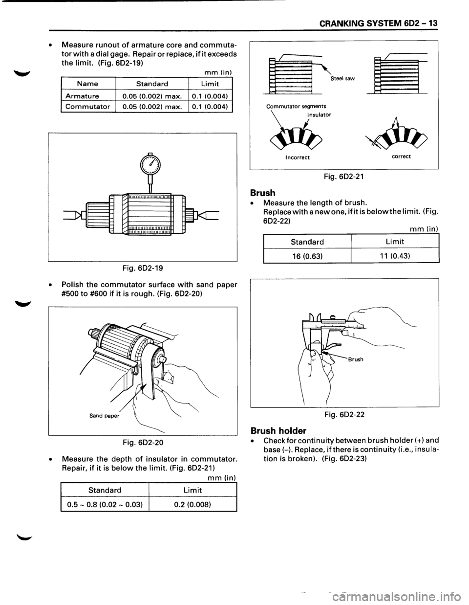
• Measure runout of armature core and commuta
tor with a dial gage. Repair or replace, if it exceeds
the limit. (Fig. 602-19)
mm(in)
Name Standard Limit
Armature 0.05 (0.002) max. 0.1 (0.004)
Commutator 0.05 (0.002) max. 0.1 (0.004)
Fig. 602-19
• Polish the commutator surface with sand paper
#500 to #600 if it is rough. (Fig. 602-20)
Sand paper
Fig. 602-20
•
Measure the depth of insulator in commutator.
Repair, if it is below the limit. (Fig. 602-21)
mm(in)
Standard Limit
0.5 -0.8 (0.02 -0.03) 0.2
(0.008)
CRANKING SYSTEM 602-13
r= I .--/
Steel saw
Commutator segments
~"
Incorrect correct
Fig. 602-21
Brush
• Measure the length of brush.
Replace with a new one, if it is belowthe limit. (Fig.
602-22)
mm(in)
Standard Limit
16 (0.63) 11 (0.43)
Fig. 602-22
Brush holder
• Check for continuity between brush holder(+) and
base(-). Replace, ifthere is continuity (i.e., insula
tion is broken). (Fig. 602-23)
Page 686 of 1928
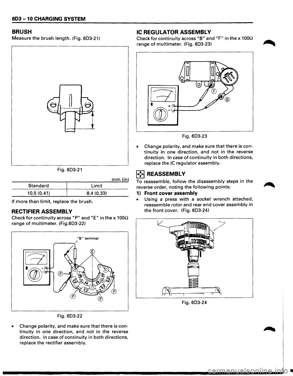
603 -10 CHARGING SYSTEM
BRUSH
Measure the brush length. (Fig. 603-21)
Fig. 603-21
mm (in)
Standard
Limit
10.5 (0.41) 8.4 (0.33)
If more than limit, replace the brush.
RECTIFIER ASSEMBL V
Check for continuity across "P" and "E" in the x 100Q
range of multimeter. (Fig.603-22)
"B" terminal r---....... /
®
Fig. 603-22
• Change polarity, and make sure that there is con
tinuity in one direction, and not in the reverse
direction.
In case of continuity in both directions,
replace the rectifier assembly.
IC REGULATOR ASSEMBL V
Check for continuity across "B" and "F" in the x 100Q
range of multimeter. (Fig. 603-23)
Fig. 603-23
• Change polarity, and make sure that there is con
tinuity in one direction, and not in the reverse
direction.
In case of continuity in both directions,
replace
the IC regulator assembly.
l•!•l REASSEMBLY
To reassemble, follow the disassembly steps in the
reverse order,
noting the following points:
1) Front cover assembly
• Using a press with a socket wrench attached,
reassemble
rotor and rear end cover assembly in
the
front cover. (Fig. 603-24)
Fig. 603-24
•