service indicator ISUZU TROOPER 1995 Workshop Manual
[x] Cancel search | Manufacturer: ISUZU, Model Year: 1995, Model line: TROOPER, Model: ISUZU TROOPER 1995Pages: 1928
Page 21 of 1928
FLUID LEVEL CHECK
A fluid loss in any system (except windshield
washer) may indicate a problem. Repair the system
at once.
Engine
oil level -Check level and add if
necessary. The best time to check the engine oil
level is
when the oil is warm. After stopping the
engine with the vehicle on a level surface, wait a
few minutes for the oil to drain back to the oil pan.
Pull
out the oil level indicator (dipstick). Wipe it
clean and push the oil level indicator back down all
the
way. Pull out the oil level indicator, keeping the
tip down, and look at the oil level on it.
Add oil, if needed, to keep the oil level above
the
"ADD" mark and between the "ADD" and
"FULL" marks in the operating range area. Avoid
overfilling the engine since this may cause engine
damage. Push
the oil level indicator back down all
the
way after taking the reading.
If you check the oil level when the oil is cold, do
not run the engine first. The cold oil will not drain
back
to the pan fast enough to give a true oil level.
Engine coolant level and condition -Check
engine coolant level in the coolant reservoir and
add engine
coolant if necessary. Inspect the engine
coolant and replace it if dirty or rusty.
Windshield washer fluid level -Check washer
fluid level in reservoir and add if necessary.
Power steering system reservoir level-Check
and keep at
proper level.
Brake master cylinder reservoir level -Check
fluid. Keep fluid at proper level. A low fluid level
can indicate
worn disc brake pads which may need
to be serviced.
Hydraulic clutch system -Check fluid l~vel in
the reservoir.
Add fluid as required.
Battery fluid level -Check fluid level in the
battery.
FLUID LEAK CHECK
Check for fuel, water, oil or other fluid leaks by
looking at the surface beneath the vehicle after it
has been parked for a while. Water dripping from
the air conditioning system after use is normal. If
you notice gasoline fumes or fluid at any time,
locate the source and correct it at once.
ENGINE OIL AND OIL FILTER
REPLACEMENT
Always use API SE, SF, SG, SH or ILSAC GF-1
quality oils of the proper viscosity.
When choosing an oil, consider the range of
temperatures the car will be operated in before the
next oil change. Then, select the recommended oil
viscosity
from the chart (Fig. OB-1).
Always change the oil and the oil filter as soon as
possible after driving in a dust storm.
MAINTENANCE AND LUBRICATION OB-5
ENGINE COOLING SYSTEM INSPECTION
Inspect coolant/anti-freeze. If coolant is dirty or
rusty, drain, flush and refill with new coolant. Keep
coolant at the proper mixture for proper freeze
protection,
corrosion inhibitor level and best engine
operating temperature.
Inspect hoses and replace if
cracked, swollen or deteriorated. Tighten hose
clamps if equipped with screw-type clamps. Clean
outside of radiator and air conditioning condenser.
Wash
filler cap and neck. To help ensure proper
operation, a pressure test of both the cooling
system and cap is also recommended.
EXHAUST SYSTEM INSPECTION
Visually inspect the exhaust pipes, muffler, heat
shields and hangers
for cracks, deterioration, or
damage.
Be alert to any changes in the sound of the exhaust
system
or any smell of fumes. These are signs the
system may be leaking or overheating. Repair the
system at once,
if these conditions exist. (See also
"Engine Exhaust Gas Safety" and "Three Way
Catalytic Converter" in Owner's manual.)
FUEL CAP, FUEL LINES, AND FUEL TANK
INSPECTION
Inspect the fuel tank, the fuel cap and the fuel lines
every
60,000 miles (96,000 km) for damage which
could cause leakage.
Inspect the fuel cap and the gasket for correct sealing
and physical damage. Replace any damaged parts.
DRIVE BELT INSPECTION
Check the belts driving the steering oil pump, the air
conditioning compressor, and the generator
for
cracks, fraying, wear, and correct tension every 30,000
miles (48,000 km). Adjust or replace as necessary.
WHEEL ALIGNMENT, BALANCE AND
TIRES OPERATION
Uneven or abnormal tire wear, or a pull right or left
on a straight and level road may show the need for
a wheel alignment. A vibration of the steering
wheel or seat at normal highway speeds means a
wheel balancing is needed. Check tire pressure
when the tires are "cold" (include the spare).
Maintain pressure as shown in the tire placard,
which is located on the driver's door lock pillar.
STEERING SYSTEM OPERATION
Be alert for any changes in steering action. An
inspection
or service is needed when the steering
wheel is harder
to turn or has too much free play, or
if there are unusual sounds when turning or parking.
Page 352 of 1928
5A2-2 DISC BRAKES
Front disc brakes
/
Rear disc brakes
I
I
Fig. 5A2-1
ON-VEHICLE SERVICE
FRONT DISC BRAKE
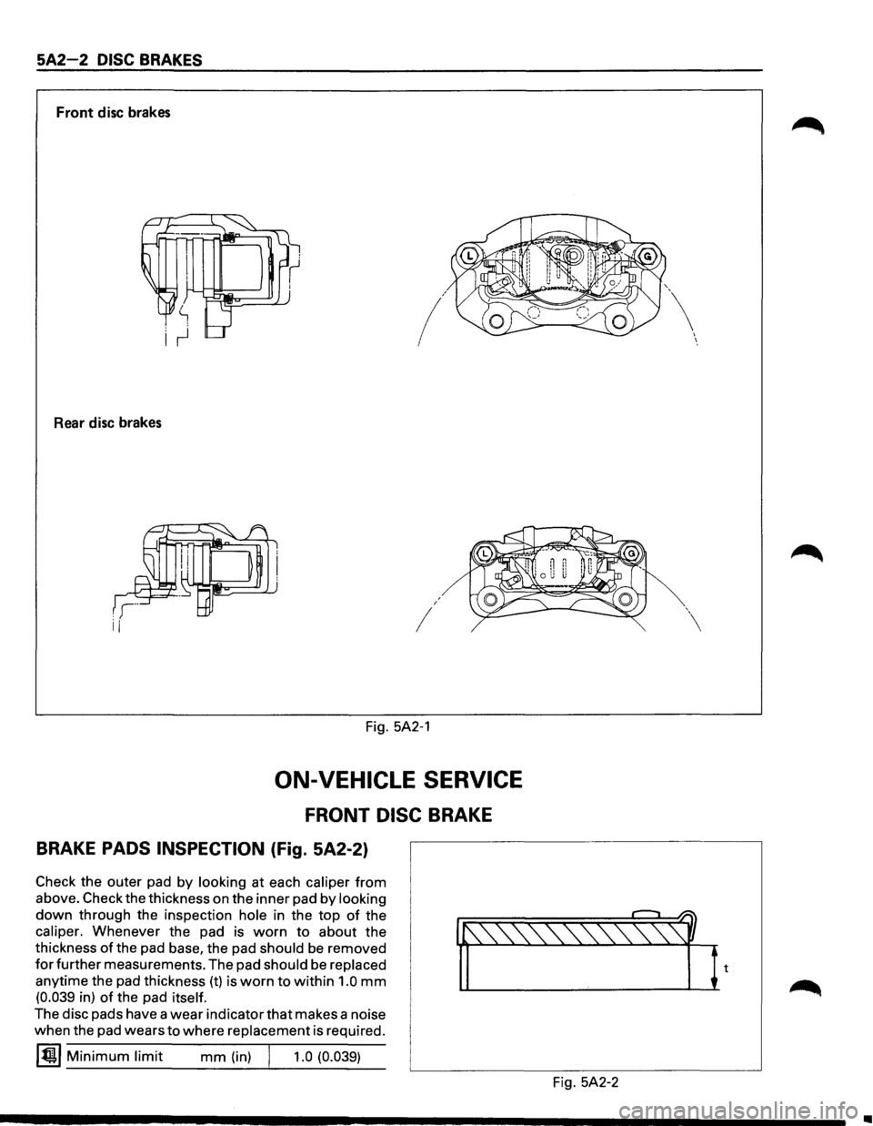
BRAKE PADS INSPECTION (Fig. 5A2-2)
Check the outer pad by looking at each caliper from
above. Check the thickness on the inner pad by looking
down through the inspection hole in the top of the
caliper. Whenever the pad is worn to about the
thickness
of the pad base, the pad should be removed
for further measurements. The pad should be replaced
anytime the pad thickness (t) is worn to within 1.0 mm
(0.039 in) of the pad itself.
The disc pads have a wear indicator that makes a noise
when the pad wears
to where replacement is required.
~~~ Minimum limit mm (in) j 1.0 (0.039)
Fig. 5A2-2
I I
•
Page 369 of 1928
REAR WHEEL ANTILOCK BRAKE SYSTEM 5A3-1
SECTION 5A3
REAR WHEEL ANTILOCK BRAKE SYSTEM
(RWAL}
w CAUTION:
• All brake attaching fasteners are an important attaching part in that they could affect performance of vital
parts and systems, and/or could result in major repair expense. They must be replaced with one of the same
part
number or with an equivalent part if replacement becomes necessary. Do not use replacement parts of
lesser quality or substitute design. Torque values must be used as specified during reassembly to assure
proper retention of these parts.
CONTENTS
Introduction . . . . . . . . . . . . . . . . . . . . . . . . . 5A3· 1
General Description . .
. . . . . . . . . . . . . . .
5A3· 1
Rear
Wheel Antilock (RWAL) Control
Parts Location . .
. . . . . . . . . . . . . . . . .
5A3· 5
System Diagram . .
. . . . . . . . . . . . . . . . . . . .
5A3· 6
Rear
Wheel Antilock (RWAL) System
Diagnostics . .
. . . . . . . . . . . . . . . . . . . . . .
5A3· 7
On-Vehicle Service . .
. . . . . . . . . . . . . . . . .
5A3·38
RWAL Electronic Brake Control
Module (EBCM) Replacement ....... 5A3-38
Antilock
(Isolation/Dump) Valve
Replacement ..................... 5A3-39
Speed Sensor Replacement
.......... 5A3-40
Main Data and Specifications ........... 5A3-41
Torque Specifications
............... 5A3-41
INTRODUCTION
This section deals with the complete diagnosis and
services
for vehicles equipped with rear wheel
antilock.
For service information regarding all other
components
of the brake system, refer to "Hydraulic
Brakes"
(Sec. SA), "Brake Booster System" (Sec. SA 1)
or "Disc Brakes" (Sec. SA2) of this Manual.
GENERAL DESCRIPTION
The rear wheel anti lock system (RWAL) is designed to
reduce rear wheel lock-up during a severe brake
application,
thus maintaining rear end stability. The
system functions
by regulating the rear hydraulic
brake line pressure. The pressure regulation is
accomplished
by an anti lock valve which is located on
the
front right side of engine room. The anti lock valve
is made up of two valves, a dump valve which releases
pressure into an accumulator and an isolation valve
which maintains rear brake pressure. The valve is
controlled
by a microcomputer which is part of the
Electronic Brake Control Module (EBCM). The
EBCM is mounted at the
front of the center
console. Under severe brake application, as pressure
is
applied to the brake pedal, the EBCM is designed to
permit the valve to do one of three functions or a
combination
of all three. The EBCM will allow the valve
to either maintain the same amount of hydraulic
pressure, release hydraulic pressure through the
dump valve into the accumulator or increase the
pressure by
pulsing the isolation valve.
The EBCM operates by receiving signals from the
speed sensor (which
is located in the differential
carrier), combination
valve and the brake light switch.
The RWAL system is connected
to the RWAL indicator
light located on the dash. An indication of the RWAL
operation and a
bulb check is performed each time the
ignition is turned
"ON". The indicator light will remain
on
for about two seconds. A RWAL system
malfunction is indicated if the RWAL indicator light
stays on, or comes on during driving. To determine the
specific
trouble, refer to "RWAL System Diagnostics"
in this section.
Page 500 of 1928
6-2 ENGINE DIAGNOSIS
SECTION 6E-DRIVEABILITY
AND EMISSIONS
This section covers emission control systems general
information, and diagnostic procedures which will lead
to repairing performance and driveability related
problems.
Emission components are covered, as well
as removal and replacement procedures.
Instructions on use
of special tools are also given.
SECTION 6F-ENGINE EXHAUST
This section has information on all exhaust system
parts, such
as tailpipes, mufflers, and the catalytic
converter.
GENERAL DESCRIPTION
ENGINE CLEANLINESS AND CARE
An automobile engine is a combination of many
machined, honed,
polished and lapped surfaces with
tolerances that are measured in the thousandths of a
millimeter (ten thousandths of an inch). Accordingly,
when any
internal engine parts are serviced, care and
cleanliness are important. Throughout this section, it
should be understood that proper cleaning and
protection
of machined surfaces and friction areas is
part
of the repair procedure. This is considered
standard shop practice even
if not specifically stated.
• A liberal coating of engine oil should be applied to
all friction areas during assembly to protect and
lubricate the surfaces on initial operation.
• Whenever valve train components, pistons, piston
rings, connecting rods, rod bearings, and
crankshaft
journal bearings are removed for
service, they should be retained in order.
• At the time of installation, they should be installed
in the same locations and with the same mating
surfaces
as when removed.
• Battery cables should be disconnected before any
major
work is performed on the engine. Failure to
disconnect
cables may result in damage to wire
harness
or other electrical parts.
• The six cylinders of this engine are identified by
numbers; Right side
cylinders 1, 3 and 5, Left side
cylinders 2, 4 and 6, as counted from crankshaft
pulley side to flywheel side.
GENERAL INFORMATION ON ENGINE
SERVICE
The following information on engine service should be
noted
carefully, as it is important in preventing damage
and contributing
to reliable engine performance.
• When raising or supporting the engine for any
reason,
do not use a jack under the oil pan. Due to
the
small clearance between the oil pan and the oil
pump strainer, jacking against the oil pan may
cause damage to the
oil pick-up unit.
• The 12-volt electrical system is capable of
damaging circuits. When performing any work
where electrical terminals could possibly be
grounded, the ground cable of the battery should
be disconnected at the battery.
• Any time the intake air duct or air cleaner is
removed, the intake opening
should be covered.
This
will protect against accidental entrance of
foreign material into the cylinder which could
cause extensive damage when the engine is
started.
ENGINE DIAGNOSIS
CONTENTS
Hard Starting . . . . . . . . . . . . . . . . . . . . . . . . . 6-3
Engine Compression
Test Procedure ..... 6-4
Rough Engine
Idling or Engine Stalling . . . 6-5
Rough Engine Running . . . . . . . . . . . . . . . . .
6-6
Hesitation . . . . . . . . . . . . . . . . . . . . . . . . . . . . 6-7
Engine Lacks
Power . . . . . . . . . . . . . . . . . . . . 6-8
Engine
Noisy .......................... 6-10
Abnormal Combustion . . . . . . . . . . . . . . . . . . 6-12
Engine Oil Consumption Excessive . . . . . . . 6-13
Fuel Consumption Excessive ............. 6-14
Oil Problems . . . . . . . . . . . . . . . . . . . . . . . . . . 6-14
Malfunction Indicator Lamp . . . . . . . . . . . . . . 6-15
Engine Oil Pressure Check ............... 6-16
Inspection of Hydraulic Lash Adjuster . . . . . 6-17
Page 698 of 1928
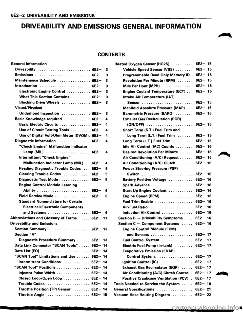
6E2-2 DRIVEABILITY AND EMISSIONS
DRIVEABILITV AND EMISSIONS GENERAL INFORMATION
CONTENTS
General Information
Driveability ....................... .
Emissions
........................ .
Maintenance
Schedule .............. .
Introduction ...................... .
Electronic Engine
Control .......... .
What This Section Contains ........ .
Blocking Drive Wheels
Visual/Physical
Underhood Inspection
6E2-3
6E2-3
6E2-3
6E2-3
6E2-3
6E2-3
6E2-3
6E2-3
Basic
Knowledge required . . . . . . . . . . . . 6E2-4
Basic Electric Circuits . . . . . . . . . . . . . .
6E2-4
Use
of Circuit Testing Tools . . . . . . . . . 6E2-4
Use
of Digital Volt-Ohm Meter (DVOM). 6E2-4
Diagnostic
Information . . . . . . . . . . . . . . . 6E2-4
"Check Engine" Malfunction Indicator
Lamp (MIL) . . . . . . . . . . . . . . . . . . . . 6E2-4
Intermittent "Check Engine"
Malfunction Indicator Lamp (MIL) . . 6E2-4
Reading Diagnostic
Trouble Codes . . . 6E2-5
Clearing
Trouble Codes . . . . . . . . . . . . 6E2-5
Diagnostic Test
Mode .............. 6E2-5
Engine Control
Module Learning
Ability . . . . . . . . . . . . . . . . . . . . . . . . 6E2-6
Field
Service Mode . . . . . . . . . . . . . . . . 6E2-6
Standard Nomenclature
for Certain
Electrical/Electronic
Components
and Systems . . . . . . . . . . . . . . . . . . . 6E2-6
Abbreviations and Glossary of Terms ..... 6E2-11
Driveability and Emissions
Section Summary ................... 6E2-12
Section .,. A"
Diagnostic Procedure Summary ...... 6E2-13
Data Link Connector
"SCAN Tools" ..... 6E2-14
Data
List (FO) ...................... 6E2-14
"SCAN Tool" Limitations and Use ...... 6E2-14
Intermittent Conditions ............ 6E2-14
"SCAN Tool" Positions ............... 6E2-14
Injector Pulse Width ............... 6E2-14
Closed Loop/Open Loop . . . . . . . . . . . .
6E2-14
Trouble Codes ................... 6E2-14
Throttle Position (TP) Sensor . . . . . . . . 6E2-14
Throttle Angle . . . . . . . . . . . . . . . . . . . 6E2-15 Heated
Oxygen
Sensor (H02S)
Vehicle Speed Sensor (VSS) ....... .
Programmable Read Only Memory ID .
Revolution
Per Minute (RPM) ...... .
Mile Per Hour (MPH) ............. .
Engine
Coolant Temperature (ECT) .. .
Intake Air Temperature (IAT)
Sensor
...................... .
Manifold Absolute Pressure (MAP) .. .
Barometric Pressure (BARO) ....... .
Exhaust Gas Recirculation
(EGR)
(ON/OFF) .................... .
Short Term (S.T.) Fuel Trim and
Long Term
(LT.) Fuel Trim ...... .
Long Term
(LT.) Fuel Trim ........ .
Idle Air Control (lAC) Counts ....... .
Desired Revolution
Per Minute ..... .
Air Conditioning (A/C) Request ..... .
Air Conditioning (A/C) Clutch ...... .
Power Steering Pressure (PSP)
Switch ...................... .
Battery Positive Voltage .......... .
Spark Advance .................. .
Start Up Engine Coolant .......... .
Engine
Speed (RPM) ............. .
Fuel Trim Enable ................ .
Air/Fuel Ratio .................. .
Induction Air Control ............. .
Section B -Driveability Symptoms ... .
Section C -Component Systems .... .
Engine
Control Module (ECM)
and
Sensors .................. .
Fuel Control System ............. .
Electric
Fuel Pump (in-tank) ....... .
Evaporative Emission
(EVAP)
Control System ................ .
Ignition Control (IC) .............. .
Exhaust Gas Recirculator
(EGR) .... .
Air Conditioning (A/C) Clutch Control .
Positive Crankcase Ventilation (PCV) .
Tools Needed
to Service the System .... .
General Specifications
............... .
Vacuum Hose Routing Diagram
........ .
6E2-15
6E2-15
6E2-15
6E2-15
6E2-15
6E2-15
6E2-15
6E2-15
6E2-15
6E2-15
6E2-15
6E2-16
6E2-16
6E2-16
6E2-16
6E2-16
6E2-16
6E2-16
6E2-16
6E2-16
6E2-16
6E2-16
6E2-16
6E2-16
6E2-16
6E2-16
6E2-17
6E2-17
6E2-17
6E2-17
6E2-17
6E2-17
6E2-17
6E2-17
6E2-18
6E2-21
6E2-22
~
... ...
•
Page 700 of 1928
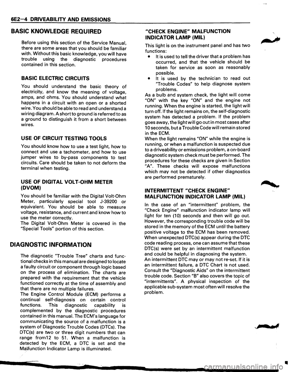
6E2-4 DRIVEABILITY AND EMISSIONS
BASIC KNOWLEDGE REQUIRED
Before using this section of the Service Manual,
there are some areas that you should be familiar
with. Without this basic knowledge, you will have
trouble using the diagnostic procedures
contained in this section.
BASIC ELECTRIC CIRCUITS
You should understand the basic theory of
electricity, and know the meaning of voltage,
amps, and ohms. You should understand what
happens in a circuit with an open or a shorted
wire. You
should be able to read and understand a
wiring diagram. A shortto ground is referred to as
a ground to distinguish it from a short between
wires.
USE OF CIRCUIT TESTING TOOLS
You should know how to use a test light, how to
connect and use a tachometer, and
how to use
jumper wires to by-pass components to test
circuits. Care
should be taken to not deform the
terminal when testing.
USE OF DIGITAL VOLT-OHM METER
(DVOM)
You should be familiar with the Digital Volt-Ohm
Meter, particularly special tool J-39200 or
equivalent. You should be able to measure
voltage, resistance, and current and know how to
use the meter correctly.
The
Digital Volt-Ohm Meter is covered in the
"Special Tools" portion of this section.
DIAGNOSTIC INFORMATION
The diagnostic "Trouble Tree" charts and func
tional checks in this manual are designed to locate
a faulty circuit or component through logic based
on the process
of elimination. The charts are
prepared
with the requirement that the vehicle
functioned correctly at the time of assembly and
that there are no multiple failures.
The Engine Control Module (ECM) performs a
continual self-diagnosis on certain control
functions. This diagnostic capability is
complemented by the diagnostic procedures
contained in this
manual. The ECM's language for
communicating the source of a malfunction is a
system
of Diagnostic Trouble Codes (DTCs). The
DTC(s) are
two or three digit numbers that can
range from12 to
51. When a malfunction is
detected by the ECM, a DTC is set and the
Malfunction Indicator Lamp is illuminated.
"CHECK ENGINE" MALFUNCTION
INDICATOR
LAMP (MIL)
This light is on the instrument panel and has two
functions:
• It is used to tell the driver that a problem has
occurred, and that the
vehicle should be
taken
for service as soon as reasonably
possible.
• It
is used by the technician to read out
'Trouble Codes" to help diagnose system
problems.
As a bulb and system check, the light will come
"ON" with the key "ON" and the engine not
running. When the engine is started, the light will
turn off. If the light remains on, the self-diagnostic
system has detected a
problem. If the problem
goes away, the light will go out in most cases after
10 seconds, but a Trouble Code will remain stored
in the
ECM.
When the light remains "ON" while the engine is
running,
or when a malfunction is suspected due
to a
driveability or emissions problem, a on-board
diagnostic system check
must be performed. The
procedures
for these checks are given in Section
"A". These checks will expose malfunctions
which may
not be detected if other diagnostics
are performed
prematurely.
INTERMITTENT "CHECK ENGINE"
MALFUNCTION INDICATOR
LAMP (MIL)
In the case of an "intermittent" problem, the
"Check Engine"
malfunction indicator lamp will
light
for ten (1 0) seconds and then will go out.
However, the corresponding
trouble code will be
stored in the
memory of the ECM until the battery
positive
voltage to the ECM has been removed.
When unexpected DTC(s) appear during the
DTC
code reading process, one can assume that these
DTC(s) were set by an intermittent malfunction
and could be helpful in diagnosing the system.
An intermittent
DTC may or may not re-set. If it is
an intermittent failure, a DTC Chart is not used.
Consult the "Diagnostic Aids" on the intermittent
trouble code. Section "B" also covers the topic of
"intermittents". A physical inspection of the
applicable sub-system most often will resolve the
problem.
II
Page 702 of 1928
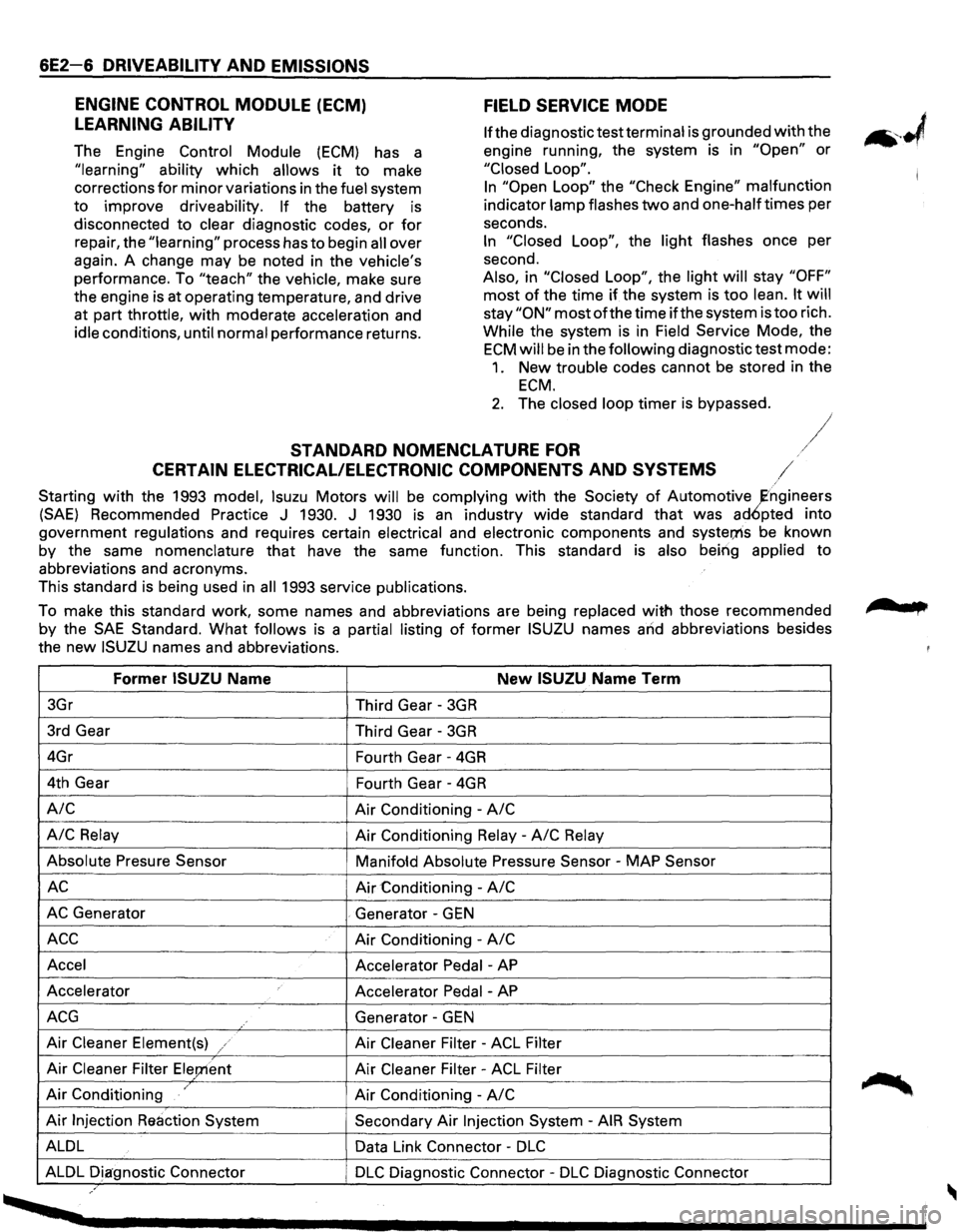
6E2-6 DRIVEABILITY AND EMISSIONS
FIELD SERVICE MODE
ENGINE
CONTROL MODULE (ECM)
LEARNING ABILITY
The Engine Control Module (ECM) has a
"learning"
ability which allows it to make
corrections
for minor variations in the fuel system
to improve driveability. If the battery is
disconnected to clear diagnostic codes, or for
repair, the "learning" process has to begin all over
again. A change
may be noted in the vehicle's
performance. To "teach" the vehicle, make sure
the engine is at operating temperature, and drive
at part throttle, with moderate acceleration and
idle conditions, until normal performance returns.
lfthe diagnostic test terminal is grounded with the
engine running, the system is in
"Open" or
"Closed Loop".
In "Open Loop" the "Check Engine" malfunction
indicator lamp flashes
two and one-halftimes per
seconds.
In "Closed Loop", the light flashes once per
second.
Also, in "Closed
Loop", the light will stay "OFF"
most of the time if the system is too lean. It will
stay"ON" mostofthetime if the system is too rich.
While the system is in Field Service Mode, the
ECM will be in the following diagnostic test mode:
1. New trouble codes cannot be stored in the
ECM.
2. The closed loop timer is bypassed.
STANDARD NOMENCLATURE FOR /
CERTAIN ELECTRICAL/ELECTRONIC COMPONENTS AND SYSTEMS /
Starting with the 1993 model, lsuzu Motors will be complying with the Society of Automotive ~ngineers
(SAE) Recommended Practice J 1930. J 1930 is an industry wide standard that was ad6pted into
government regulations and requires certain electrical and electronic components and
syster;ns be known
by the same
nomenclature that have the same function. This standard is also being applied to
abbreviations and acronyms.
This standard is being used in
all 1993 service publications.
To make this standard work, some names and abbreviations are being replaced
with those recommended
by the
SAE Standard. What follows is a partial listing of former ISUZU names and abbreviations besides
the
new ISUZU names and abbreviations.
Former ISUZU Name New ISUZU Name Term
3Gr
Third Gear -3GR
3rd Gear
Third Gear -3GR
4Gr
Fourth Gear -4GR
4th Gear
Fourth Gear -4GR
A/C Air Conditioning -A/C
A/C
Relay Air Conditioning Relay -A/C Relay
Absolute Presure Sensor
Manifofd Absolute Pressure Sensor -MAP Sensor
AC Air Conditioning -A/C
AC Generator . Generator -GEN
ACC Air Conditioning -A/C
Accel
Accelerator Pedal -AP
Accelerator
Accelerator Pedal -AP
ACG Generator -GEN
Air Cleaner Element(s) / Air Cleaner Filter -ACL Filter
Air Cleaner Filter Ele;nent Air Cleaner Filter -ACL Filter
Air Conditioning / Air Conditioning -A/C
Air Injection Reaction System Secondary Air Injection System -AIR System
ALDL Data Link Connector -
DLC
ALDL Diagnostic Connector DLC Diagnostic Connector -DLC Diagnostic Connector ,.
, ....
Page 708 of 1928
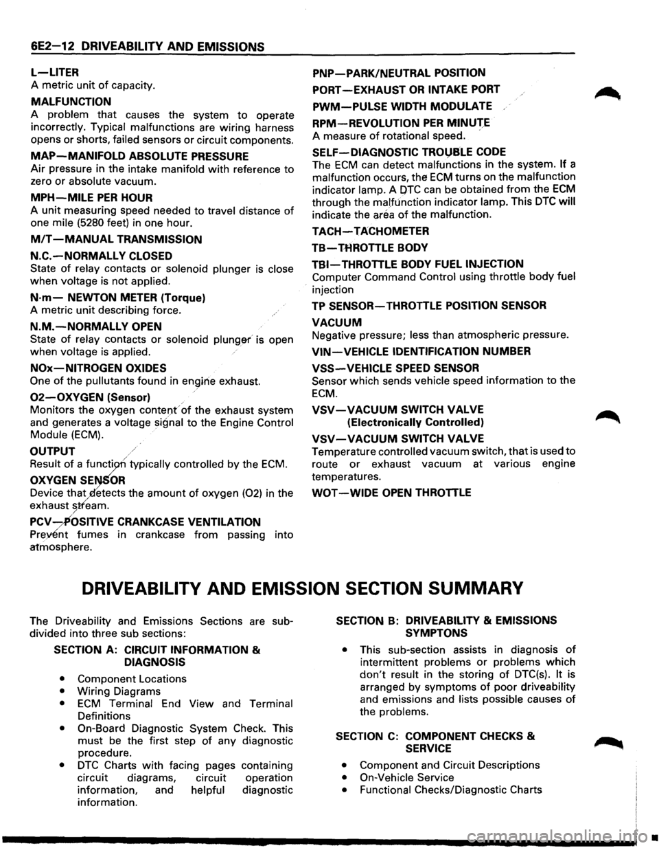
6E2-12 DRIVEABILITY AND EMISSIONS
L-LITER
A metric unit of capacity.
MALFUNCTION
A problem that causes the system to operate
incorrectly. Typical malfunctions are wiring harness
opens
or shorts, failed sensors or circuit components.
MAP-MANIFOLD ABSOLUTE PRESSURE
Air pressure in the intake manifold with reference to
zero or absolute vacuum.
MPH-MILE PER HOUR
A unit measuring speed needed to travel distance of
one mile (5280 feet) in one hour.
MIT -MANUAL TRANSMISSION
N.C.-NORMALLY CLOSED
State of relay contacts or solenoid plunger is close
when voltage is not applied.
N·m-NEWTON METER (Torque)
A metric unit describing force.
N.M.-NORMALLY OPEN
State of relay contacts or solenoid plung&r' is open
when voltage is applied.
NOx-NITROGEN OXIDES
One of the pullutants found in engirie exhaust.
02-0XYGEN (Sensor)
Monitors the oxygen contel)f of the exhaust system
and generates a
voltage signal to the Engine Control
Module (ECM).
OUTPUT
Result of a functi typically controlled by the ECM.
OXYGEN SE OR
Device that etects the amount of oxygen (02) in the
exhaust
stfeam. /
PCV-~OSITIVE CRANKCASE VENTILATION
Prey£nt fumes in crankcase from passing into
atmosphere.
PNP-PARK/NEUTRAL POSITION
PORT-EXHAUST OR INTAKE PORT
PWM-PULSE WIDTH MODULATE
RPM-REVOLUTION PER MINUTE
A measure of rotational speed.
SELF-DIAGNOSTIC TROl)SLE CODE
The ECM can detect malfunctions in the system. If a
malfunction occurs, the ECM turns on the malfunction
indicator lamp. A OTC can be obtained from the ECM
through the malfunction indicator lamp. This DTC will
indicate the area of the malfunction.
TACH-TACHOMETER
TB-THROTTLE BODY
TBI-THROTTLE BODY FUEL INJECTION
Computer Command Control using throttle body fuel
injection
TP SENSOR-THROTTLE POSITION SENSOR
VACUUM
Negative pressure; less than atmospheric pressure.
VIN-VEHICLE IDENTIFICATION NUMBER
VSS-VEHICLE SPEED SENSOR
Sensor which sends vehicle speed information to the
ECM.
VSV-VACUUM SWITCH VALVE
(Electronically Controlled)
VSV-VACUUM SWITCH VALVE
Temperature controlled vacuum switch, that is used to
route or exhaust vacuum at various engine
temperatures.
WOT -WIDE OPEN THROTTLE
DRIVEABILITV AND EMISSION SECTION SUMMARY
The Driveability and Emissions Sections are sub
divided into three sub sections:
SECTION A: CIRCUIT INFORMATION &
DIAGNOSIS
• Component Locations
• Wiring Diagrams
• ECM Terminal End View and Terminal
Definitions
• On-Board Diagnostic System Check. This
must be the first step of any diagnostic
procedure.
• DTC Charts with facing pages containing
circuit diagrams, circuit operation
information, and
helpful diagnostic
information.
SECTION B: DRIVEABILITY & EMISSIONS
SYMPTONS
• This sub-section assists in diagnosis of
intermittent problems or problems which
don't result in the storing of DTC(s). It is
arranged
by symptoms of poor driveability
and emissions and lists possible causes of
the problems.
SECTION C: COMPONENT CHECKS &
SERVICE
• Component and Circuit Descriptions
• On-Vehicle Service
• Functional
Checks/Diagnostic Charts
•
Page 732 of 1928
6E2-36 DRIVEABILITV AND EMISSIONS
ON-BOARD DIAGNOSTIC (OBD) SYSTEM CHECK
The on-board diagnostic system check is an organized approach to identifying a problem created by an Electronic
Engine
Control System malfunction. It must be the starting point for any driveability complaint diagnosis, because
it directs the service technician to the next logical step in diagnosing the complaint. Understanding the chart and
using
it correclty will reduce diagnostic time and prevent the unnecessary replacement of good parts.
Test Description:
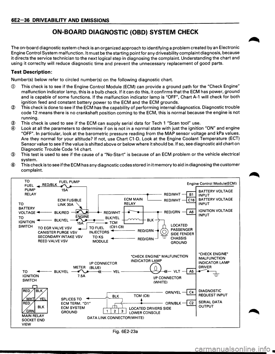
Number(s) below refer to circled number(s) on the following diagnostic chart.
CD This check is to see if the Engine Control Module (ECM) can provide a ground path for the "Check Engine"
malfunction indicator lamp, this is a bulb check. If it can do this, it confirms that the ECM has power, ground
and is capable
of some functions. If the malfunction indicator lamp is "OFF", Chart A-1 will check for both
ignition feed and constant battery power to the
ECM and the ECM grounds.
® This check is done to see if the ECM has the capability of performing internal diagnostics. Diagnostic trouble
code
12 means there is no crankshaft position coming to the ECM, this is normal because the engine is not
running.
® This check is used to see if the ECM can supply serial data for Tech 1 "Scan tool" use.
@ Look at all the parameters to determine if on is not in a normal state with just the ignition "ON" and engine
"OFF". In particular, look at the barometric pressure reading from the MAP sensor voltage and kPa values.
Are they normal for
your altitude? If not, use Chart C1-D. Look at the Engine Coolant Temperature (ECT)
Sensor value to see if the value is shifted above or below where it should be. If so, see diagnostic aid chart on
Diagnostic Trouble
Code 14 chart.
@ This test is used to see if the cause of a "No-Start" is because of an ECM problem or the vehicle electrical
system.
® This check is to see ifthe ECM has any diagnostic codes stored in it memory to aid in diagnosing the customer
complaint.
TO FUEL
PUMP
RELAY 15A
,------------+--RED/WHT Engine
Control Module(ECM)
BATTERY
VOLTAGE INPUT
ECM FUSIBLE L_ __ RED/WHT
~~TTERY LINK 30A ~
VOLTAGE ..,.,.f----BLK/RED
TO
~t-----tr-RED/WHT -----,t--+---.-RED/GRN
IGNITION BLK/YEL J-------BLK/YEL -TCM BLK
SWITCH
TO EGR VALVE VSV
CANISTER PURGE VSV SECONDARYINTAKEVSV REED VALVE VSV
TO FUEL (C91-C8)
INJECTORS RED/GRN
TO KS MODULE ..,._ ___ RED/GRN
LOCATED
PASSENGER
SIDE
FENDER CHASSIS
GROUND
"CHECK ENGINE" MALFUNCTION
I/P CONNECTOR INDICATOR LAMP
METER (BLUE)
f'7:' TO ..,._ __ BLK/YEL ~~VEL~(;-VLT IGNITION
SWITCH 7.5A
SPLICES TO
ECM TERM. "D1" ECM SYSTEM
GROUND
DATA LINK CONNECTOR(WHITE)
Fig. 6E2-23a
1/P CONNECTOR
(WHITE)
BATTERY VOLTAGE INPUT
IGNITION
VOLTAGE INPUT
"CHECK ENGINE"
MALFUNCTION
INDICATOR
LAMP DRIVER
-=:J._
DIAGNOSTIC
REQUEST INPUT
•
Page 786 of 1928
6E2-90 DRIVEABILITY AND EMISSIONS
INTERMITTENTS
Definition: Problem may or may not turn "ON" the
"Check Engine" malfunction indicator lamp or store
Diagnostic
Trouble Code (DTC).
DO NOT use the DTC charts in "Engine Components/
Wiring Diagrams/Diagnostic
Charts," Section "6E2-A"
for intermittent problem. The fault must be present to
locate the problem. If a fault is intermittent, use of DTC
charts may result in replacement of good parts.
•
• Most intermittent problems are caused by faulty
electrical
connections or wiring. Perform careful
visual/physical
check as described at start of
"Symptoms," Section "6E2-B." Check for:
Poor mating
of the connector halves. or
terminal not fully seated in the connector body
(backed out).
Improperly formed or damaged terminal. All
connector
terminals in the problem circuit
should be carefully reformed or replaced to
insure proper contact tension.
Poor
terminal to wire connection. This
requires removing the
terminal from the
connector body to check. Refer to
SECTION 8
"Wiring Harness Service,"
If a visual/physical check does not find the cause
of the problem, the car can be driven with a
voltmeter connected to a suspected circuit. A
"Scan tool" can also be used to help detect
intermittent conditions. An abnormal
voltage, or
"Scan" tool reading, when the problem occurs,
indicates the
problem may be in that circuit. If the wiring
and connectors check
OK, and a DTC was
stored
for a circuit having a sensor, except for
DTC(s) 44 and 45, substitute a known good sensor
and recheck.
• Loss of DTC memory. To check, disconnect
throttle position (TP) sensor and idle engine until
"Check
Engine" malfunction indicator lamp comes
"ON". DTC 21 should be stored, and kept in
memory when ignition is turned "OFF". If not, the
Engine
Control Module (ECM) is faulty.
•
An intermittent "Check Engine" malfunction
indicator
lamp with no stored DTC may be caused
by:
Ignition coil shorted to ground and arcing at
spark
plug wires or plugs.
"Check
Engine" malfunction indicator lamp
wire to ECM shorted to ground.
Diagnostic
"test" terminal wire to ECM,
shorted to ground.
ECM grounds, refer to ECM wiring diagrams.
• Check for an electrical system interference caused
by a defective
relay, ECM driven solenoid, or
switch. They can cause a sharp electrical surge.
Normally, the problem will occur when the faulty
component is operated.
• Check for improper installation of electrical
options such as lights, 2 way radios, etc.
• Ignition control wires should be routed away from
spark plug wires, electronic ignition (EI) wires, El
housing, coil and generator. Ground wire from
ECM to El should have a good connection.
• If problem has not been found, refer to "ECM
Connector Symptom" charts at the end of
"Symptoms," Section "6E2-B."
HARD START
Definition: Engine cranks OK, but does not start for a
long time. Does eventually run, or may
start
but immediately dies.
PRELIMINARY CHECKS
• Perform the careful visual/physical checks as
described at start of "Symptoms," Section "6E2-
B".
•
Make sure the driver is using the correct starting
procedure.
SENSORS
• CHECK: Engine coolant temperature sensor using
a
"Scan tool", compare engine coolant
temperature with ambient temperature
on
cold engine. -
If engine coolant temperature
readings
is 5 degrees greater than or less than
ambient air temperature on a
cold
engine, check resistance in engine
coolant temperature sensor circuit
or
sensor itself. Compare engine coolant
temperature sensor resistance value
to the "Diagnostic Aids" chart on
DTC
14 chart.
• CHECK: Manifold absolute pressure sensor.
Check for flooding and/or correct sensor
for vehicle.
• CHECK: TP sensor for binding or a high TP sensor
voltage with the throttle closed (should
read between 0.54 volt and 1.25 volts.)