ISUZU TROOPER 1998 Service Owners Manual
Manufacturer: ISUZU, Model Year: 1998, Model line: TROOPER, Model: ISUZU TROOPER 1998Pages: 3573, PDF Size: 60.36 MB
Page 91 of 3573
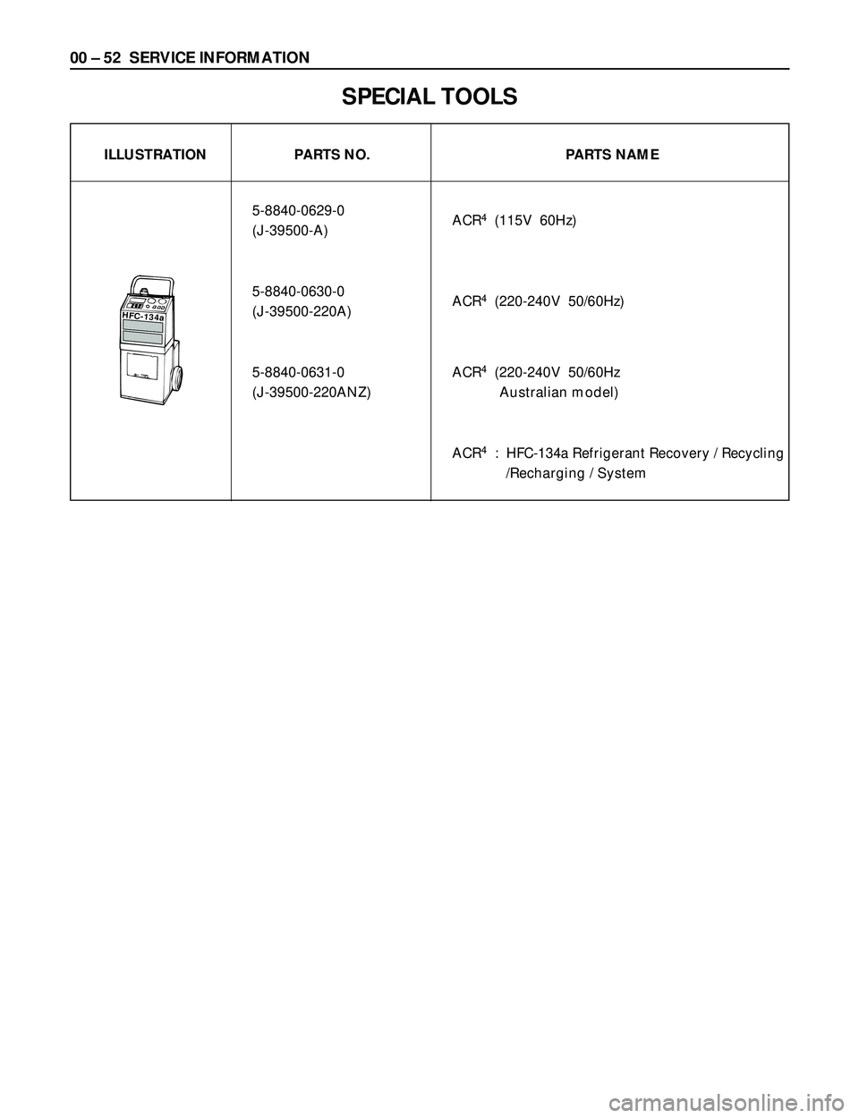
00 Ð 52 SERVICE INFORMATION
HFC-134a
SPECIAL TOOLS
ILLUSTRATION PARTS NO. PARTS NAME
5-8840-0629-0
ACR
4(115V 60Hz)
(J-39500-A)
5-8840-0630-0
ACR
4(220-240V 50/60Hz)
(J-39500-220A)
5-8840-0631-0 ACR
4(220-240V 50/60Hz
(J-39500-220ANZ) Australian model)
ACR
4: HFC-134a Refrigerant Recovery / Recycling
/Recharging / System
Page 92 of 3573

SERVICE INFORMATION 00 Ð 53
ILLUSTRATION PARTS NO. PARTS NAME
5-8840-2007-0
Drive plate holder
(J-7624)
5-8840-0122-0
Drive plate puller
(J-33944-A)
5-8840-0621-0
Forcing screw
(J-33944-4)
5-8840-0620-0
Pulley puller pilot
(J-38424)
5-8840-0111-0
Pulley puller
(J-8433)
5-8840-0622-0
Pulley puller leg
(J-24092-2)
5-8840-0118-0
Pulley installer
(J-33940)
5-8840-0007-0
Drive handle
(J-8092)
DKV-14D TYPE
901RX056
Page 93 of 3573

00 Ð 54 SERVICE INFORMATION
ILLUSTRATION PARTS NO. PARTS NAME
5-8840-2007-0
Drive plate holder
(J-7624)
5-8840-0122-0
Drive plate puller
(J-33944-A)
5-8840-0621-0
Forcing screw
(J-33944-4)
5-8840-0121-0
Pulley puller pilot
(J-33943)
5-8840-0111-0
Pulley puller
(J-8433)
5-8840-120-0
Shaft seal remover and installer
(J-33942)
5-8840-0368-0
Shaft seal guide
(J-34614)
5-8840-0118-0
Pulley installer
(J-33940)
5-8840-0007-0
Drive handle
(J-8092)
DKS-15CH TYPE
901RX056
Page 94 of 3573
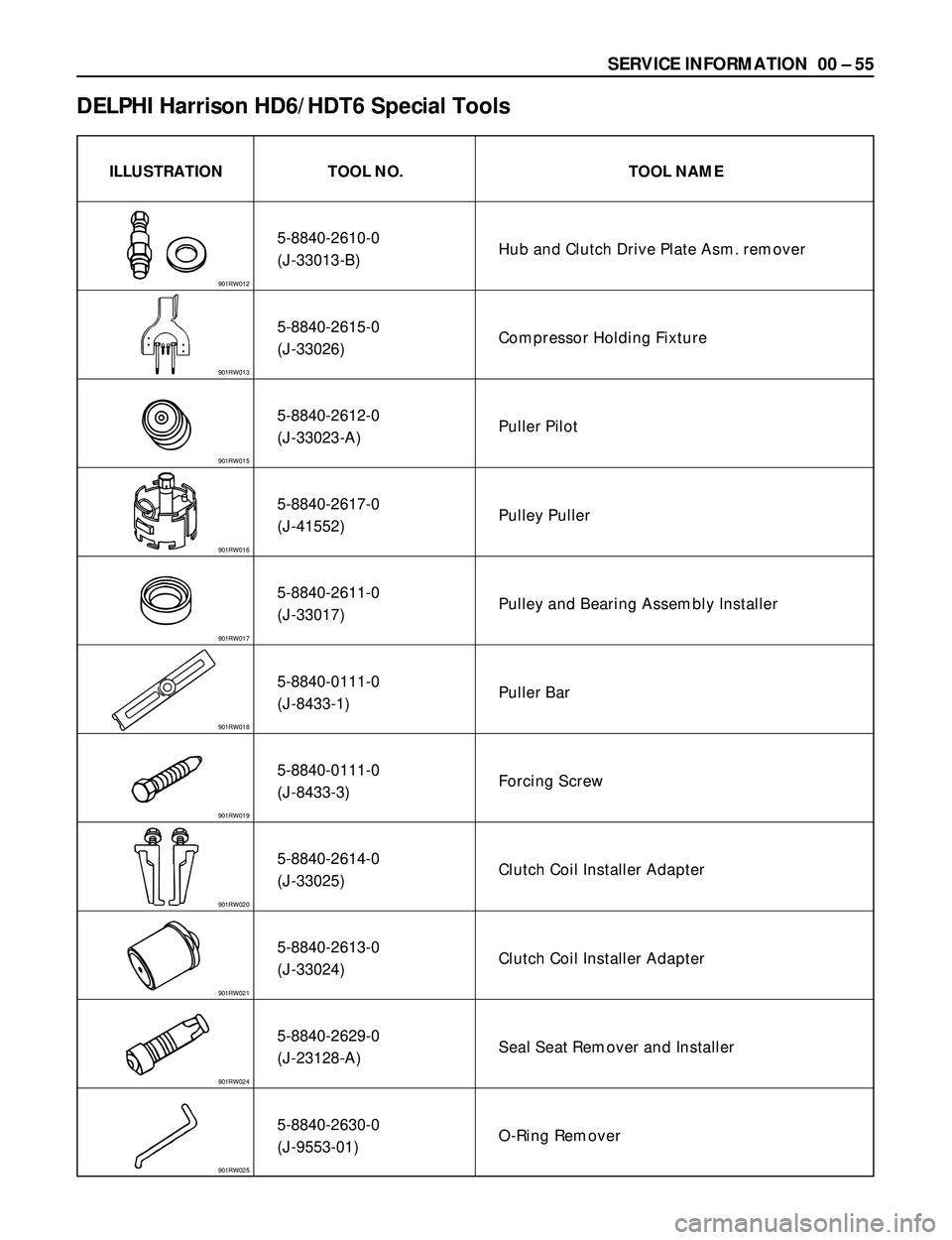
SERVICE INFORMATION 00 Ð 55
ILLUSTRATION TOOL NO. TOOL NAME
5-8840-2610-0
Hub and Clutch Drive Plate Asm. remover
(J-33013-B)
5-8840-2615-0
Compressor Holding Fixture
(J-33026)
5-8840-2612-0
Puller Pilot
(J-33023-A)
5-8840-2617-0
Pulley Puller
(J-41552)
5-8840-2611-0
Pulley and Bearing Assembly Installer
(J-33017)
5-8840-0111-0
Puller Bar
(J-8433-1)
5-8840-0111-0
Forcing Screw
(J-8433-3)
5-8840-2614-0
Clutch Coil Installer Adapter
(J-33025)
5-8840-2613-0
Clutch Coil Installer Adapter
(J-33024)
5-8840-2629-0
Seal Seat Remover and Installer
(J-23128-A)
5-8840-2630-0
O-Ring Remover
(J-9553-01)
DELPHI Harrison HD6/HDT6 Special Tools
901RW012
901RW013
901RW015
901RW016
901RW017
901RW018
901RW019
901RW020
901RW021
901RW024
901RW025
Page 95 of 3573

00 Ð 56 SERVICE INFORMATION
901RW032
ILLUSTRATION TOOL NO. TOOL NAME
5-8840-2609-0
O-Ring Installer
(J-33011)
5-8840-0368-0
Shaft Seal Protector
(J-34614)
5-8840-2616-0
Pressure Testing Connector
(J-39893)
901RW026
901RW027
901RW032
Page 96 of 3573
CAUTION
When fasteners are removed, always
reinstall them at the same location from
which they were removed. If a fastener
needs to be replaced, use the correct part
number fastener for that application. If the
correct part number fastener is not available,
a fastener of equal size and strength (or
stronger) may be used. Fasteners that are not reused, and those
requiring thread locking compound, will be
called out. The correct torque values must
be used when installing fasteners that
require it. If the above conditions are not
followed, parts or system damage could
result.
HEATING AND VENTILATION 1A Ð 1
SECTION 1A
HEATING AND VENTILATION
CONTENTS
PAGE
General Description.....................................................1AÐ 2
Heater...............................................................1AÐ 2
Control Lever Assembly................................................1AÐ 3
Ventilation...........................................................1AÐ 3
Air Select Knob.......................................................1AÐ 4
Air Source Select Lever................................................1AÐ 4
Fan Control Knob.....................................................1AÐ 4
Temperature Control Knob.............................................1AÐ 4
Ceramic Heater.......................................................1AÐ 5
On-Vehicle Service......................................................1AÐ 6
Heater Unit..........................................................1AÐ 6
Heater Core and/or Mode Door..........................................1AÐ 8
Heater Mode Control Link Unit..........................................1AÐ10
Heater Temperature Control Link Unit....................................1AÐ12
Blower Assembly.....................................................1AÐ14
Blower Link Unit and/or Mode Door......................................1AÐ16
Blower Motor........................................................1AÐ18
Rear Heater Duct, Defroster Nozzle and Ventilation Duct....................1AÐ20
Center and/or Side Vent...............................................1AÐ22
Control Lever Assembly and/or Control Cables............................1AÐ24
Control Panel Illumination Bulb..........................................1AÐ27
Resistor.............................................................1AÐ28
Ceramic Heater and/or Full Hot Switch...................................1AÐ30
Page 97 of 3573
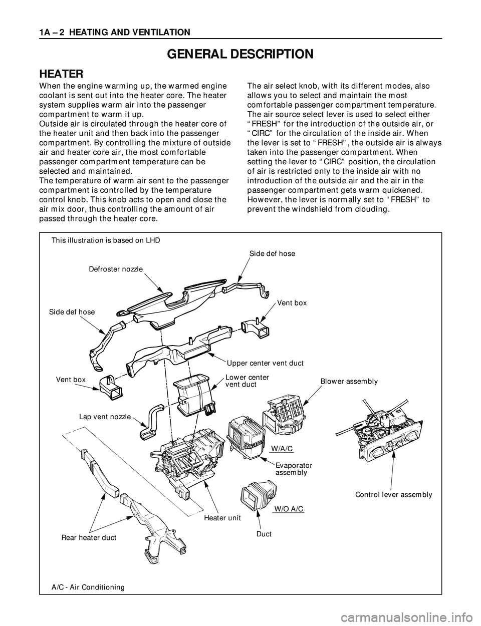
When the engine warming up, the warmed engine
coolant is sent out into the heater core. The heater
system supplies warm air into the passenger
compartment to warm it up.
Outside air is circulated through the heater core of
the heater unit and then back into the passenger
compartment. By controlling the mixture of outside
air and heater core air, the most comfortable
passenger compartment temperature can be
selected and maintained.
The temperature of warm air sent to the passenger
compartment is controlled by the temperature
control knob. This knob acts to open and close the
air mix door, thus controlling the amount of air
passed through the heater core.The air select knob, with its different modes, also
allows you to select and maintain the most
comfortable passenger compartment temperature.
The air source select lever is used to select either
ÒFRESHÓ for the introduction of the outside air, or
ÒCIRCÓ for the circulation of the inside air. When
the lever is set to ÒFRESHÓ, the outside air is always
taken into the passenger compartment. When
setting the lever to ÒCIRCÓ position, the circulation
of air is restricted only to the inside air with no
introduction of the outside air and the air in the
passenger compartment gets warm quickened.
However, the lever is normally set to ÒFRESHÓ to
prevent the windshield from clouding.
1A Ð 2 HEATING AND VENTILATION
GENERAL DESCRIPTION
HEATER
Side def hose
Vent box
Upper center vent duct
Lower center
vent ductBlower assembly
Control lever assembly Evaporator
assembly W/A/C
W/O A/C
Duct Heater unit
Lap vent nozzle Vent box Side def hoseDefroster nozzle
Rear heater duct
A/C - Air Conditioning This illustration is based on LHD
Page 98 of 3573
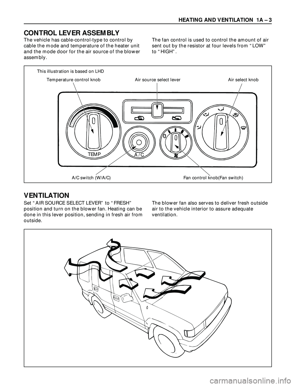
This illustration is based on LHD
Temperature control knob
A/C switch (W/A/C)
TEMP
A/C
Fan control knob(Fan switch) Air source select lever Air select knob
HEATING AND VENTILATION 1A Ð 3
The vehicle has cable-control-type to control by
cable the mode and temperature of the heater unit
and the mode door for the air source of the blower
assembly.The fan control is used to control the amount of air
sent out by the resistor at four levels from ÒLOWÓ
to ÒHIGHÓ.
CONTROL LEVER ASSEMBLY
VENTILATION
Set ÒAIR SOURCE SELECT LEVERÓ to ÒFRESHÓ
position and turn on the blower fan. Heating can be
done in this lever position, sending in fresh air from
outside.The blower fan also serves to deliver fresh outside
air to the vehicle interior to assure adequate
ventilation.
Page 99 of 3573
1A Ð 4 HEATING AND VENTILATION
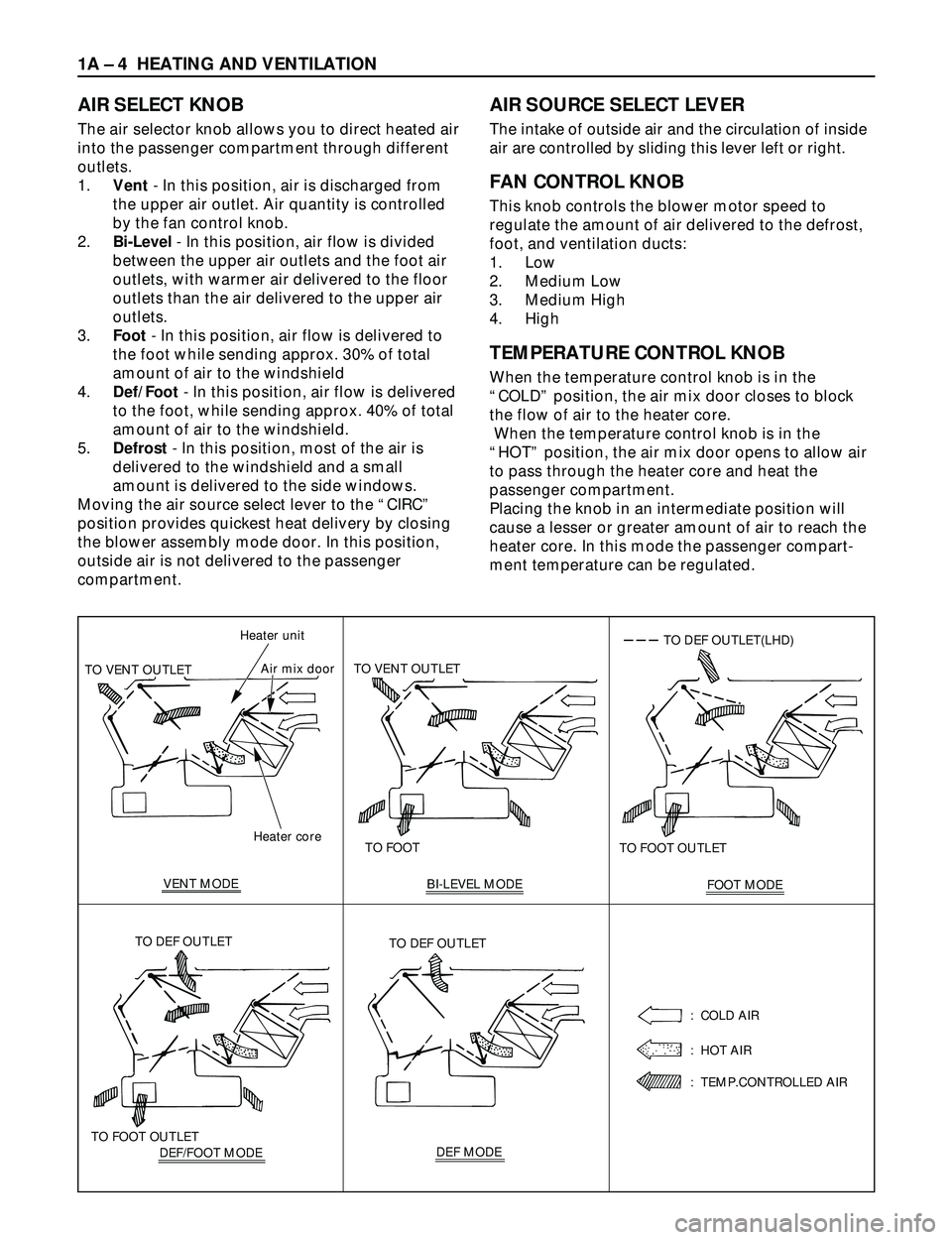
AIR SELECT KNOB
The air selector knob allows you to direct heated air
into the passenger compartment through different
outlets.
1.Vent- In this position, air is discharged from
the upper air outlet. Air quantity is controlled
by the fan control knob.
2.Bi-Level- In this position, air flow is divided
between the upper air outlets and the foot air
outlets, with warmer air delivered to the floor
outlets than the air delivered to the upper air
outlets.
3.Foot- In this position, air flow is delivered to
the foot while sending approx. 30% of total
amount of air to the windshield
4.Def/Foot- In this position, air flow is delivered
to the foot, while sending approx. 40% of total
amount of air to the windshield.
5.Defrost- In this position, most of the air is
delivered to the windshield and a small
amount is delivered to the side windows.
Moving the air source select lever to the ÒCIRCÓ
position provides quickest heat delivery by closing
the blower assembly mode door. In this position,
outside air is not delivered to the passenger
compartment.
AIR SOURCE SELECT LEVER
The intake of outside air and the circulation of inside
air are controlled by sliding this lever left or right.
FAN CONTROL KNOB
This knob controls the blower motor speed to
regulate the amount of air delivered to the defrost,
foot, and ventilation ducts:
1. Low
2. Medium Low
3. Medium High
4. High
TEMPERATURE CONTROL KNOB
When the temperature control knob is in the
ÒCOLDÓ position, the air mix door closes to block
the flow of air to the heater core.
When the temperature control knob is in the
ÒHOTÓ position, the air mix door opens to allow air
to pass through the heater core and heat the
passenger compartment.
Placing the knob in an intermediate position will
cause a lesser or greater amount of air to reach the
heater core. In this mode the passenger compart-
ment temperature can be regulated.
Heater core Heater unit
TO VENT OUTLETAir mix door
VENT MODETO FOOT TO VENT OUTLET
BI-LEVEL MODE
FOOT MODE TO FOOT OUTLET
TO DEF OUTLET(LHD)
DEF/FOOT MODE TO FOOT OUTLETTO DEF OUTLETDEF MODE TO DEF OUTLET
: COLD AIR
: HOT AIR
: TEMP.CONTROLLED AIR
Page 100 of 3573
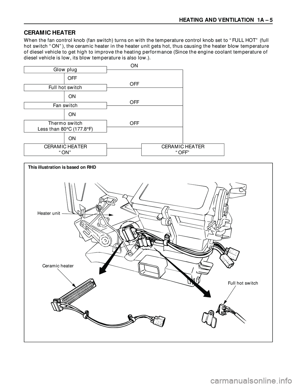
Full hot switch Ceramic heater Heater unit
HEATING AND VENTILATION 1A Ð 5
CERAMIC HEATER
When the fan control knob (fan switch) turns on with the temperature control knob set to ÒFULL HOTÓ (full
hot switch ÒONÓ), the ceramic heater in the heater unit gets hot, thus causing the heater blow temperature
of diesel vehicle to get high to improve the heating performance (Since the engine coolant temperature of
diesel vehicle is low, its blow temperature is also low.).
Glow plug
Full hot switch
Fan switch
Thermo switch
Less than 80¡C (177.8¡F)
CERAMIC HEATER
ÒONÓCERAMIC HEATER
ÒOFFÓ
OFF
ON
OFF
OFF
OFF
ON
ON
ON
This illustration is based on RHD