ISUZU TROOPER 1998 Service Repair Manual
TROOPER 1998
ISUZU
ISUZU
https://www.carmanualsonline.info/img/61/57184/w960_57184-0.png
ISUZU TROOPER 1998 Service Repair Manual
Trending: engine oil, mileage, glove box, drain bolt, drive shaft, power steering, fuse chart
Page 101 of 3573
1A Ð 6 HEATING AND VENTILATION
ON-VEHICLE SERVICE
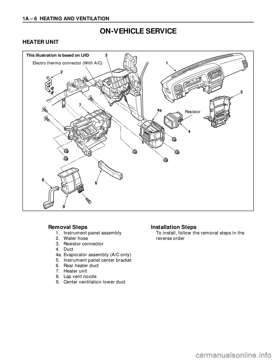
HEATER UNIT
4a
5
3
4
2
6
9
8
7
1Electro thermo connector (With A/C)
Resistor
Removal Steps
1. Instrument panel assembly
2. Water hose
3. Resistor connector
4. Duct
4a. Evaporator assembly (A/C only)
5. Instrument panel center bracket
6. Rear heater duct
7. Heater unit
8. Lap vent nozzle
9. Center ventilation lower duct
Installation Steps
To install, follow the removal steps in the
reverse order
This illustration is based on LHD
Page 102 of 3573
HEATING AND VENTILATION 1A Ð 7
INSTALLATION
To install, follow the removal steps in the reverse order,
noting the following points:
1. When handling the ECM and the control unit, be
careful not to make any improper connection of the
connectors.
2. Adjust control lever assembly cables.
Refer to ÒCONTROL LEVER ASSEMBLYÓ installation
steps in this section.
3. When installing the heater unit, defroster nozzle and
center vent duct, be sure that proper seal is made,
without any gap between then.
REMOVAL
Preparation:
·Disconnect the battery ground cable
·Drain engine coolant
·Discharge and recover refrigerant (W/A/C)
(Refer to Section 1B ÒREFRIGERANT RECOVERYÓ)
1. Instrument Panel Assembly
Refer to Section 10 ÒBODYÓ for INSTRUMENT PANEL
ASSEMBLY removal procedure.
2. Water Hose
Disconnect water hoses at heater unit.
3. Resistor Connector
4. Duct
4a. Evaporator Assembly
Refer to Section 1B ÒAIR CONDITIONINGÓ for
Evaporator Assembly removal procedure.
5. Instrument panel center bracket
6. Rear Heater Duct
7. Heater Unit
8. Lap vent nozzle
9. Center ventilation lower duct
Page 103 of 3573
1A Ð 8 HEATING AND VENTILATION
Removal Steps
1. Heater unit
2. Duct
3. Case (Mode control)
4. Case (Temperature control)
5. Heater core
6. Mode door
Installation Steps
To install, follow the removal steps in the
reverse order.
HEATER CORE AND/OR MODE DOOR
4
5
3
2 1
6 This illustration is based on LHD
Page 104 of 3573
HEATING AND VENTILATION 1A Ð 9
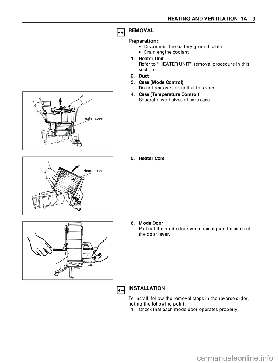
REMOVAL
Preparation:
·Disconnect the battery ground cable
·Drain engine coolant
1. Heater Unit
Refer to ÒHEATER UNITÓ removal procedure in this
section.
2. Duct
3. Case (Mode Control)
Do not remove link unit at this step.
4. Case (Temperature Control)
Separate two halves of core case.
Heater core
5. Heater Core
Heater core
6. Mode Door
Pull out the mode door while raising up the catch of
the door lever.
INSTALLATION
To install, follow the removal steps in the reverse order,
noting the following point:
1. Check that each mode door operates properly.
Page 105 of 3573
1A Ð 10 HEATING AND VENTILATION
Removal Steps
1. Heater unit
2. Case (Mode control)
3. Washer and mode main lever
4. Rod
5. Mode sub-lever
6. Door lever
7. Clip
Installation Steps
To install, follow the removal steps in the
reverse order.
HEATER MODE CONTROL LINK UNIT
This illustration is based on LHD
1
2
5
6
7
3
4
5
46
75
Page 106 of 3573
HEATING AND VENTILATION 1A Ð 11
REMOVAL
Preparation:
·Disconnect the battery ground cable
·Drain engine coolant
1. Heater Unit
Refer to ÒHEATER UNITÓ removal procedure in this
section.
2. Case (Mode Control)
Remove the case (Mode control) from heater unit.
3. Washer and Mode Main Lever
4. Rod
5. Mode Sub-Lever
Press the tab of the sub-lever inward, and take out the
sub-lever.
6. Door Lever
Pull out the door lever while raising up the catch of
the door lever.
INSTALLATION
To install, follow the removal steps in the reverse order,
noting the following points:
1. Apply grease to mode sub-lever and to the abrasive
surface of the heater unit.
2. After installing the link unit, check to see if the link
unit operates correctly.
Page 107 of 3573
1A Ð 12 HEATING AND VENTILATION
Removal Steps
1. Heater unit
2. Case (Temperature control)
3. Rod
4. Sub-lever
5. Door lever
6. Clip
Installation Steps
To install, follow the removal steps in the
reverse order.
HEATER TEMPERATURE CONTROL LINK UNIT
2
5
6
6
4
5
1 3 This illustration is based on LHD
Page 108 of 3573
HEATING AND VENTILATION 1A Ð 13
REMOVAL
Preparation:
·Disconnect the battery ground cable
·Drain engine coolant
1. Heater Unit
Refer to ÒHEATER UNITÓ removal procedure in this
section.
2. Case (Temperature Control)
Remove the case (Temperature control) from the
heater unit.
3. Rod
4. Sub-Lever
5. Door Lever
Pull out the door lever while raising up the catch of
the door lever.
6. Clip
INSTALLATION
To install, follow the removal steps in the reverse order,
noting the following points:
1. Apply grease to sub-lever and to the abrasive surface
of the heater unit.
2. After installing the link unit, check to see if the link
unit operates correctly.
Page 109 of 3573
1A Ð 14 HEATING AND VENTILATION
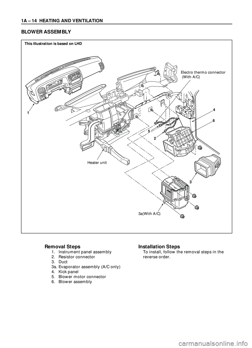
Removal Steps
1. Instrument panel assembly
2. Resistor connector
3. Duct
3a. Evaporator assembly (A/C only)
4. Kick panel
5. Blower motor connector
6. Blower assembly
Installation Steps
To install, follow the removal steps in the
reverse order.
BLOWER ASSEMBLY
2
3a(With A/C)
3
Heater unit
Electro thermo connector
(With A/C)
14
6
5
This illustration is based on LHD
Page 110 of 3573
HEATING AND VENTILATION 1A Ð 15
REMOVAL
Preparation:
·Disconnect the battery ground cable
·Discharge and recover refrigerant (W/A/C)
(Refer to Section 1B ÒREFRIGERANT RECOVERYÓ)
1. Instrument Panel Assembly
Refer to Section 10 ÒBODYÓ for INSTRUMENT PANEL
ASSEMBLY removal procedure.
2. Resistor Connector
3. Duct
3a. Evaporator Assembly (A/C only)
Refer to Section 1B ÒAIR CONDITIONINGÓ for
EVAPORATOR ASSEMBLY removal procedure.
4. Kick panel
5. Blower Motor Connector
6. Blower Assembly
INSTALLATION
To install, follow the removal steps in the reverse order,
noting the following point:
1. Adjust Control Lever Assembly Cables
Refer to ÒCONTROL LEVER ASSEMBLYÓ installation
procedure in this section.
Trending: four wheel drive, wiper blades, Wiring diagrams, engine oil capacity, brake system diagram, brake pads, recommended oil
