ISUZU TROOPER 1998 Service Repair Manual
TROOPER 1998
ISUZU
ISUZU
https://www.carmanualsonline.info/img/61/57184/w960_57184-0.png
ISUZU TROOPER 1998 Service Repair Manual
Trending: oil additives, controls, fuses, dashboard, open hood, battery, seat adjustment
Page 111 of 3573
1A Ð 16 HEATING AND VENTILATION
Removal Steps
1. Blower assembly
2. Lower case
3. Upper case
4. Mode door
5. Sub-lever
6. Door lever
Installation Steps
To install, follow the removal steps in the
reverse order.
BLOWER LINK UNIT AND/OR MODE DOOR
This illustration is based on LHD
1
3
6
24 5
Page 112 of 3573
HEATING AND VENTILATION 1A Ð 17
REMOVAL
Preparation:
Disconnect the battery ground cable
1. Blower Assembly
Refer to ÒBLOWER ASSEMBLYÓ removal procedure
in this section.
2. Lower Case
3. Upper Case
Separate upper case and slit the lining parting face
with a knife.
INSTALLATION
To install, follow the removal steps in the reverse order,
noting the following points:
1. Apply grease to the door lever and to the abrasive
surface of the upper case.
2. Apply an adhesive to parting face of lining when
assembling upper case.
Page 113 of 3573
3 4 21
5
6
1A Ð 18 HEATING AND VENTILATION
Removal Steps
1. Blower motor connector
2. Attaching screw
3. Blower motor assembly
4. Clip
5. Fan
6. Blower motor
Installation Steps
To install, follow the removal steps in the
reverse order.
BLOWER MOTOR
This illustration is based on LHD
Page 114 of 3573
HEATING AND VENTILATION 1A Ð 19
REMOVAL
Preparation:
Disconnect the battery ground cable
1. Blower Motor Connector
2. Attaching Screw
3. Blower Motor Assembly
4. Clip
5. Fan
6. Blower Motor
INSTALLATION
To install, follow the removal steps in the reverse order.
Page 115 of 3573
1A Ð 20 HEATING AND VENTILATION
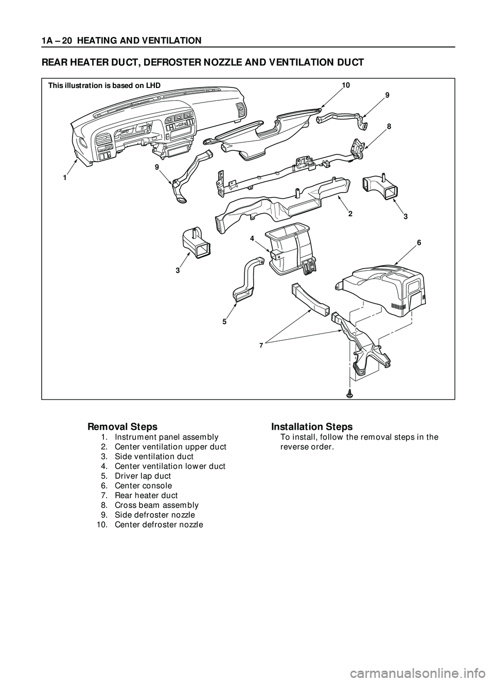
REAR HEATER DUCT, DEFROSTER NOZZLE AND VENTILATION DUCT
Removal Steps
1. Instrument panel assembly
2. Center ventilation upper duct
3. Side ventilation duct
4. Center ventilation lower duct
5. Driver lap duct
6. Center console
7. Rear heater duct
8. Cross beam assembly
9. Side defroster nozzle
10. Center defroster nozzle
Installation Steps
To install, follow the removal steps in the
reverse order.
7
9
9
10
8
6
3
5
1
3
4
2
This illustration is based on LHD
Page 116 of 3573
HEATING AND VENTILATION 1A Ð 21
INSTALLATION
To install, follow the removal steps in the reverse order,
noting the following point:
1. Connect each duct and nozzle securely leaving no
clearance between them and making no improper
matching.
REMOVAL
Preparation:
Disconnect the battery ground cable
1. Instrument panel assembly
·Refer to Section 10 ÒBODYÓ for INSTRUMENT
PANEL ASSEMBLY removal procedure.
2. Center ventilation upper duct
3. Side ventilation duct
4. Center ventilation lower duct
5. Driver lap duct
6. Center console
7. Rear heater duct
·Refer to Section 10 ÒBODYÓ for CONSOLES
removal procedure.
8. Cross beam assembly
·Refer to Section 10 ÒBODYÓ for CROSS BEAM
ASSEMBLY removal procedure.
9. Side defroster nozzle
10. Center defroster nozzle
Page 117 of 3573
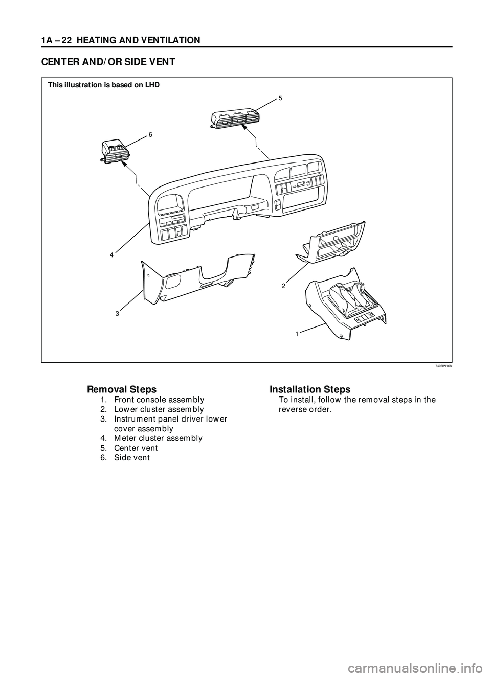
1A Ð 22 HEATING AND VENTILATION
Removal Steps
1. Front console assembly
2. Lower cluster assembly
3. Instrument panel driver lower
cover assembly
4. Meter cluster assembly
5. Center vent
6. Side vent
Installation Steps
To install, follow the removal steps in the
reverse order.
CENTER AND/OR SIDE VENT
6
5
3
1 2
4
This illustration is based on LHD
740RW168
Page 118 of 3573
HEATING AND VENTILATION 1A Ð 23
INSTALLATION
To install, follow the removal steps in the reverse order.
REMOVAL
1. Front console assembly
2. Lower cluster assembly
3. Instrument panel driver lower cover assembly
4. Meter cluster assembly
·Refer to Section 10 ÒBODYÓ for INSTRUMENT
PANEL ASSEMBLY removal procedure.
5. Center vent
·Remove screws and the center vent from center
cluster while prying up the center vent catch
portions.
6. Side vent
·Remove screws and the side vent from center
cluster while prying up the side vent catch
portions.
Page 119 of 3573
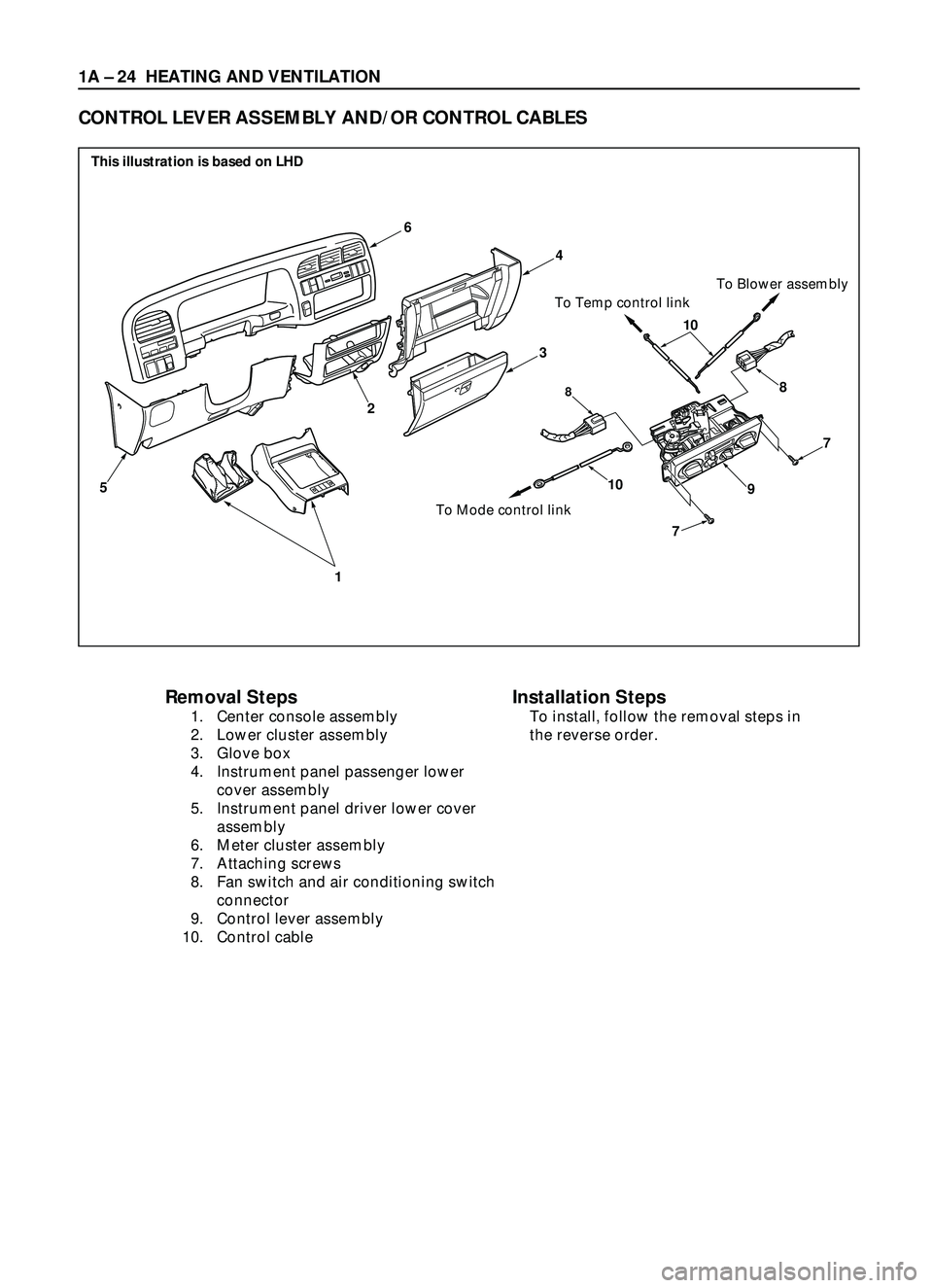
1A Ð 24 HEATING AND VENTILATION
Removal Steps
1. Center console assembly
2. Lower cluster assembly
3. Glove box
4. Instrument panel passenger lower
cover assembly
5. Instrument panel driver lower cover
assembly
6. Meter cluster assembly
7. Attaching screws
8. Fan switch and air conditioning switch
connector
9. Control lever assembly
10. Control cable
CONTROL LEVER ASSEMBLY AND/OR CONTROL CABLES
6
1
5
2
10
7
7
88
910
To Mode control linkTo Temp control linkTo Blower assembly
4
3
Installation Steps
To install, follow the removal steps in
the reverse order.
This illustration is based on LHD
Page 120 of 3573
HEATING AND VENTILATION 1A Ð 25
REMOVAL
Preparation:
Disconnect the battery ground cable
1. Front console assembly
2. Lower cluster assembly
3. Glove box
4. Instrument panel passenger lower cover
5. Instrument panel driver lower cover
6. Meter cluster assembly
Refer to Section 10 ÒBODYÓ for INSTRUMENT PANEL
ASSEMBLY removal procedure.
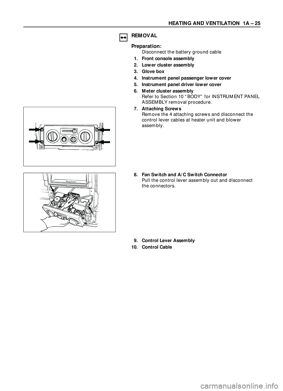
7. Attaching Screws
Remove the 4 attaching screws and disconnect the
control lever cables at heater unit and blower
assembly.
8. Fan Switch and A/C Switch Connector
Pull the control lever assembly out and disconnect
the connectors.
9. Control Lever Assembly
10. Control Cable
Trending: dimensions, power windows, Rear axle, suspension, open gas tank, power door locks, heater


