ISUZU TROOPER 1998 Service Repair Manual
Manufacturer: ISUZU, Model Year: 1998, Model line: TROOPER, Model: ISUZU TROOPER 1998Pages: 3573, PDF Size: 60.36 MB
Page 1611 of 3573
4JG2-NA/4JG2-TURBO ENGINE 6A2 Ð 9
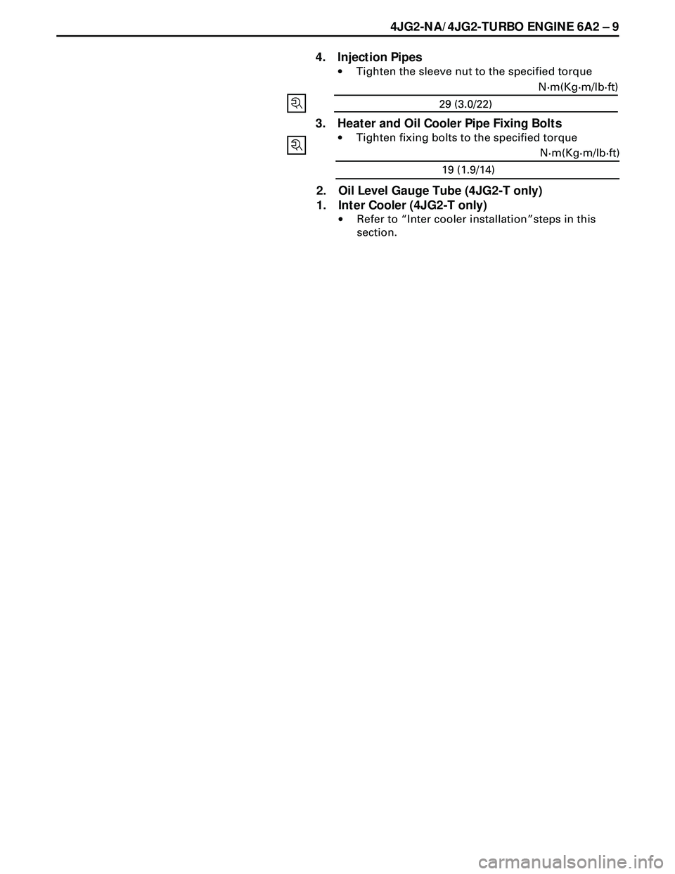
4. Injection Pipes
·Tighten the sleeve nut to the specified torque
3. Heater and Oil Cooler Pipe Fixing Bolts
·Tighten fixing bolts to the specified torque
2. Oil Level Gauge Tube (4JG2-T only)
1. Inter Cooler (4JG2-T only)
·Refer to ÒInter cooler installationÓsteps in this
section.19 (1.9/14)N·m(Kg·m/lb·ft)
29 (3.0/22)N·m(Kg·m/lb·ft)
Page 1612 of 3573
6A2 Ð 10 4JG2-NA/4JG2-TURBO ENGINE
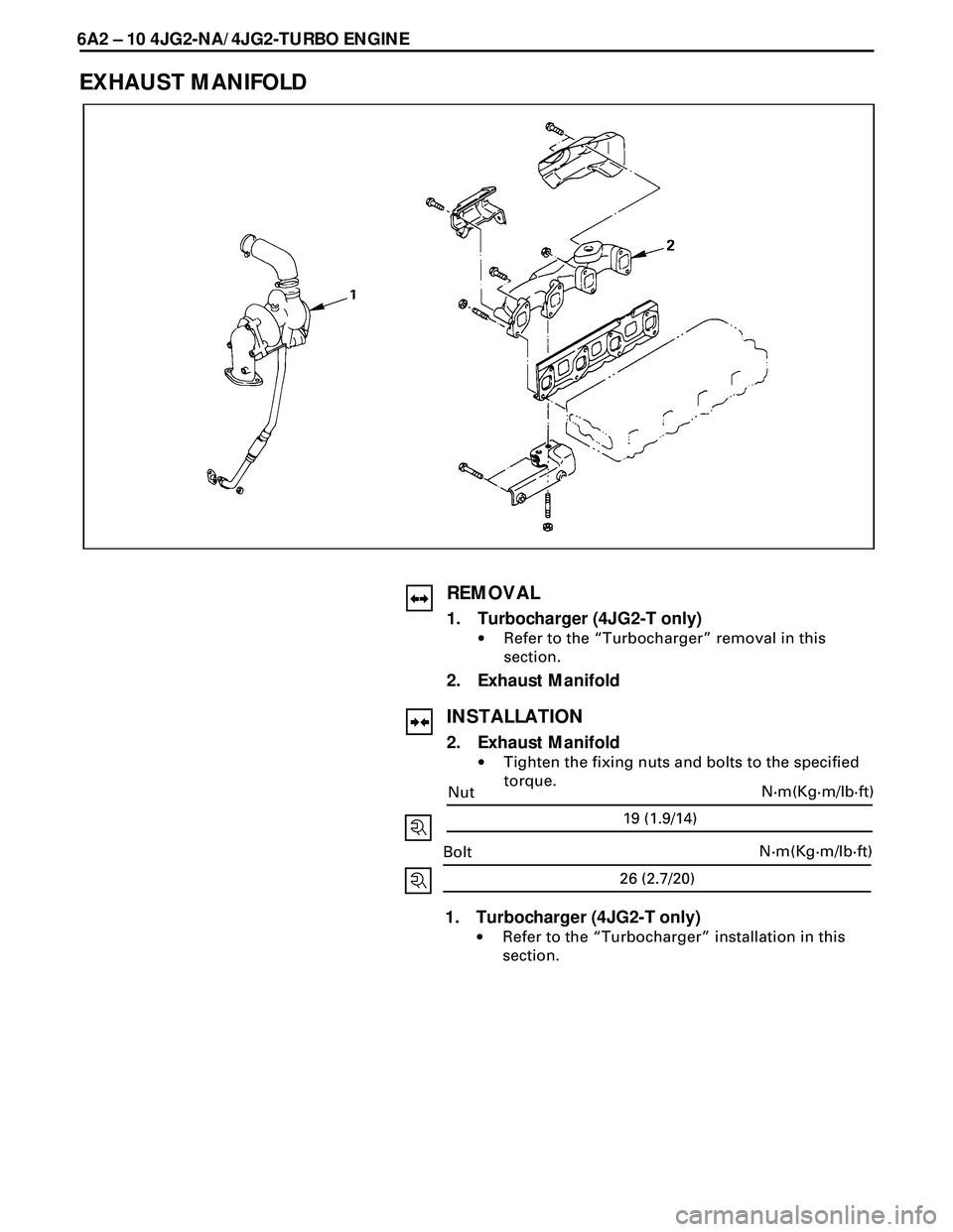
EXHAUST MANIFOLD
REMOVAL
1. Turbocharger (4JG2-T only)
·Refer to the ÒTurbochargerÓ removal in this
section.
2. Exhaust Manifold
INSTALLATION
2. Exhaust Manifold
·Tighten the fixing nuts and bolts to the specified
torque.
1. Turbocharger (4JG2-T only)
·Refer to the ÒTurbochargerÓ installation in this
section.
26 (2.7/20)
N·m(Kg·m/lb·ft)
Bolt
19 (1.9/14)
N·m(Kg·m/lb·ft)
Nut
Page 1613 of 3573
4JG2-NA/4JG2-TURBO ENGINE 6A2 Ð 11
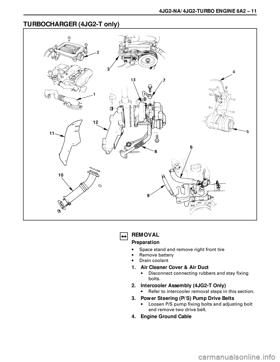
TURBOCHARGER (4JG2-T only)
REMOVAL
Preparation
·Space stand and remove right front tire
·Remove battery
·Drain coolant
1. Air Cleaner Cover & Air Duct
·Disconnect connecting rubbers and stay fixing
bolts.
2. Intercooler Assembly (4JG2-T Only)
·Refer to intercooler removal steps in this section.
3. Power Steering (P/S) Pump Drive Belts
·Loosen P/S pump fixing bolts and adjusting bolt
and remove two drive belt.
4. Engine Ground Cable
Page 1614 of 3573
6A2Ð 12 4JG2-NA/4JG2-TURBO ENGINE
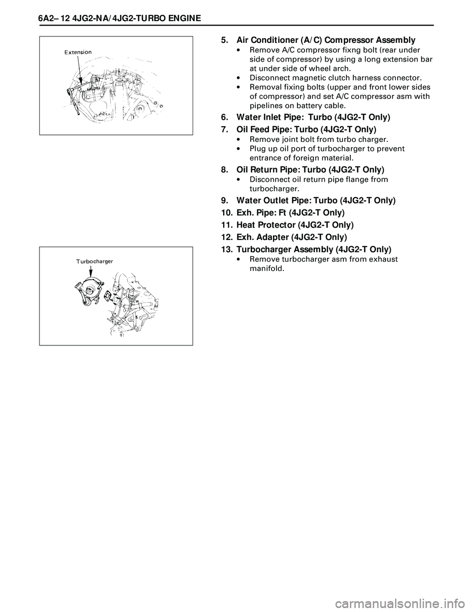
5. Air Conditioner (A/C) Compressor Assembly
·Remove A/C compressor fixng bolt (rear under
side of compressor) by using a long extension bar
at under side of wheel arch.
·Disconnect magnetic clutch harness connector.
·Removal fixing bolts (upper and front lower sides
of compressor) and set A/C compressor asm with
pipelines on battery cable.
6. Water Inlet Pipe: Turbo (4JG2-T Only)
7. Oil Feed Pipe: Turbo (4JG2-T Only)
·Remove joint bolt from turbo charger.
·Plug up oil port of turbocharger to prevent
entrance of foreign material.
8. Oil Return Pipe: Turbo (4JG2-T Only)
·Disconnect oil return pipe flange from
turbocharger.
9. Water Outlet Pipe: Turbo (4JG2-T Only)
10. Exh. Pipe: Ft (4JG2-T Only)
11. Heat Protector (4JG2-T Only)
12. Exh. Adapter (4JG2-T Only)
13. Turbocharger Assembly (4JG2-T Only)
·Remove turbocharger asm from exhaust
manifold.
Page 1615 of 3573
4JG2-NA/4JG2-TURBO ENGINE 6A2 Ð 13
26 (2.7/20)N·m(Kg·m/lb·ft)
INSTALLATION
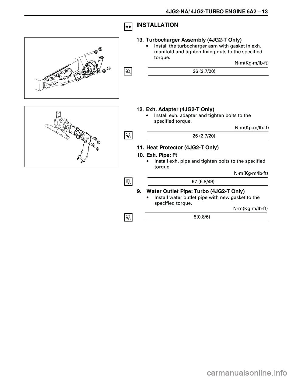
13. Turbocharger Assembly (4JG2-T Only)
·Install the turbocharger asm with gasket in exh.
manifold and tighten fixing nuts to the specified
torque.
12. Exh. Adapter (4JG2-T Only)
·Install exh. adapter and tighten bolts to the
specified torque.
11. Heat Protector (4JG2-T Only)
10. Exh. Pipe: Ft
·Install exh. pipe and tighten bolts to the specified
torque.
9. Water Outlet Pipe: Turbo (4JG2-T Only)
·Install water outlet pipe with new gasket to the
specified torque.
26 (2.7/20)N·m(Kg·m/lb·ft)
67 (6.8/49)N·m(Kg·m/lb·ft)
8(0.8/6)N·m(Kg·m/lb·ft)
Page 1616 of 3573
6A2Ð 14 4JG2-NA/4JG2-TURBO ENGINE
8. Oil Return Pipe: Turbo (4JG2-T Only)
·Install oil return pipe with new gasket in
turbocharger and tighten joint bolt to the
specified torque.
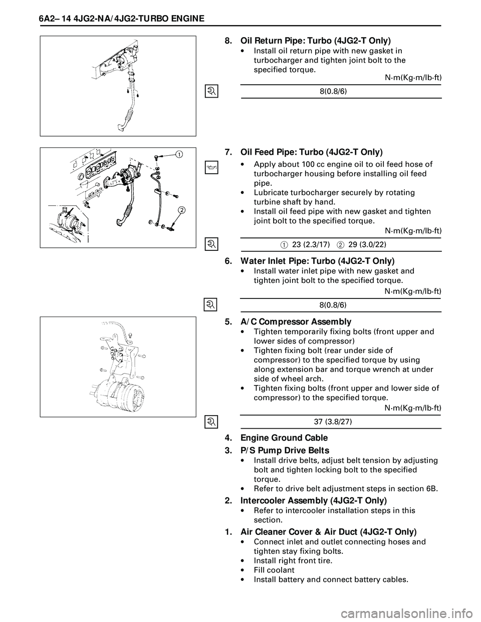
7. Oil Feed Pipe: Turbo (4JG2-T Only)
·Apply about 100 cc engine oil to oil feed hose of
turbocharger housing before installing oil feed
pipe.
·Lubricate turbocharger securely by rotating
turbine shaft by hand.
·Install oil feed pipe with new gasket and tighten
joint bolt to the specified torque.
6. Water Inlet Pipe: Turbo (4JG2-T Only)
·Install water inlet pipe with new gasket and
tighten joint bolt to the specified torque.
4. Engine Ground Cable
3. P/S Pump Drive Belts
·Install drive belts, adjust belt tension by adjusting
bolt and tighten locking bolt to the specified
torque.
·Refer to drive belt adjustment steps in section 6B.
2. Intercooler Assembly (4JG2-T Only)
·Refer to intercooler installation steps in this
section.
1. Air Cleaner Cover & Air Duct (4JG2-T Only)
·Connect inlet and outlet connecting hoses and
tighten stay fixing bolts.
·Install right front tire.
·Fill coolant
·Install battery and connect battery cables.
5. A/C Compressor Assembly
·Tighten temporarily fixing bolts (front upper and
lower sides of compressor)
·Tighten fixing bolt (rear under side of
compressor) to the specified torque by using
along extension bar and torque wrench at under
side of wheel arch.
·Tighten fixing bolts (front upper and lower side of
compressor) to the specified torque.
8(0.8/6)N·m(Kg·m/lb·ft)
123 (2.3/17)229 (3.0/22)N·m(Kg·m/lb·ft)
8(0.8/6)N·m(Kg·m/lb·ft)
37 (3.8/27)N·m(Kg·m/lb·ft)
Page 1617 of 3573
4JG2-NA/4JG2-TURBO ENGINE 6A2 Ð 15
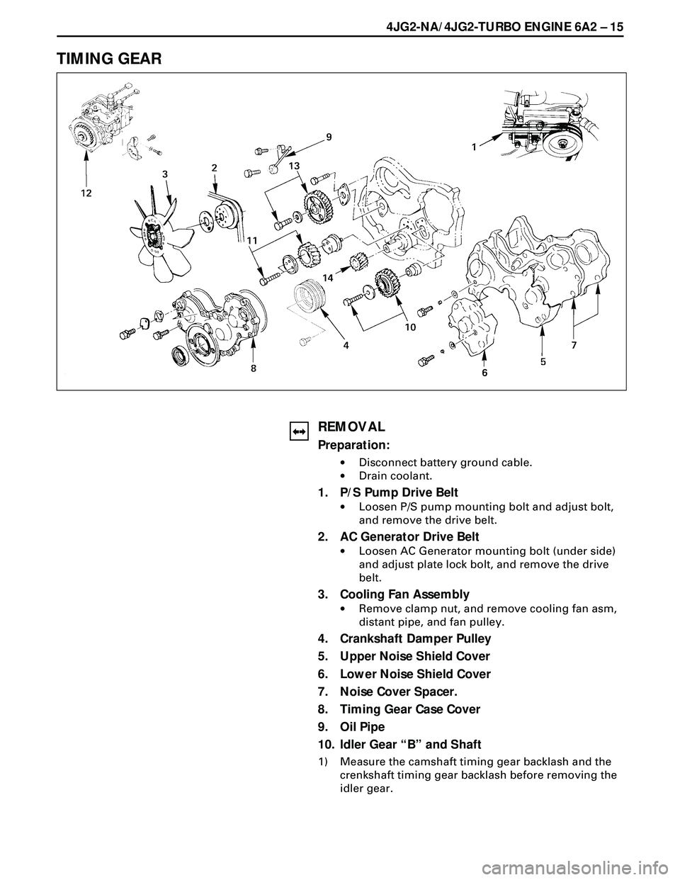
TIMING GEAR
REMOVAL
Preparation:
·Disconnect battery ground cable.
·Drain coolant.
1. P/S Pump Drive Belt
·Loosen P/S pump mounting bolt and adjust bolt,
and remove the drive belt.
2. AC Generator Drive Belt
·Loosen AC Generator mounting bolt (under side)
and adjust plate lock bolt, and remove the drive
belt.
3. Cooling Fan Assembly
·Remove clamp nut, and remove cooling fan asm,
distant pipe, and fan pulley.
4. Crankshaft Damper Pulley
5. Upper Noise Shield Cover
6. Lower Noise Shield Cover
7. Noise Cover Spacer.
8. Timing Gear Case Cover
9. Oil Pipe
10. Idler Gear ÒBÓ and Shaft
1) Measure the camshaft timing gear backlash and the
crenkshaft timing gear backlash before removing the
idler gear.
Page 1618 of 3573
6A2 Ð 16 4JG2-NA/4JG2-TURBO ENGINE
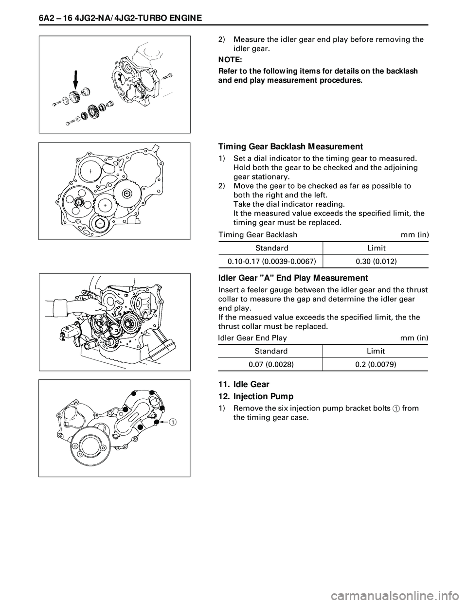
2) Measure the idler gear end play before removing the
idler gear.
NOTE:
Refer to the following items for details on the backlash
and end play measurement procedures.
Timing Gear Backlash Measurement
1) Set a dial indicator to the timing gear to measured.
Hold both the gear to be checked and the adjoining
gear stationary.
2) Move the gear to be checked as far as possible to
both the right and the left.
Take the dial indicator reading.
It the measured value exceeds the specified limit, the
timing gear must be replaced.
Idler Gear "A" End Play Measurement
Insert a feeler gauge between the idler gear and the thrust
collar to measure the gap and determine the idler gear
end play.
If the measued value exceeds the specified limit, the the
thrust collar must be replaced.
Standard
mm (in) Timing Gear Backlash
0.10-0.17 (0.0039-0.0067)Limit
0.30 (0.012)
11. Idle Gear
12. Injection Pump
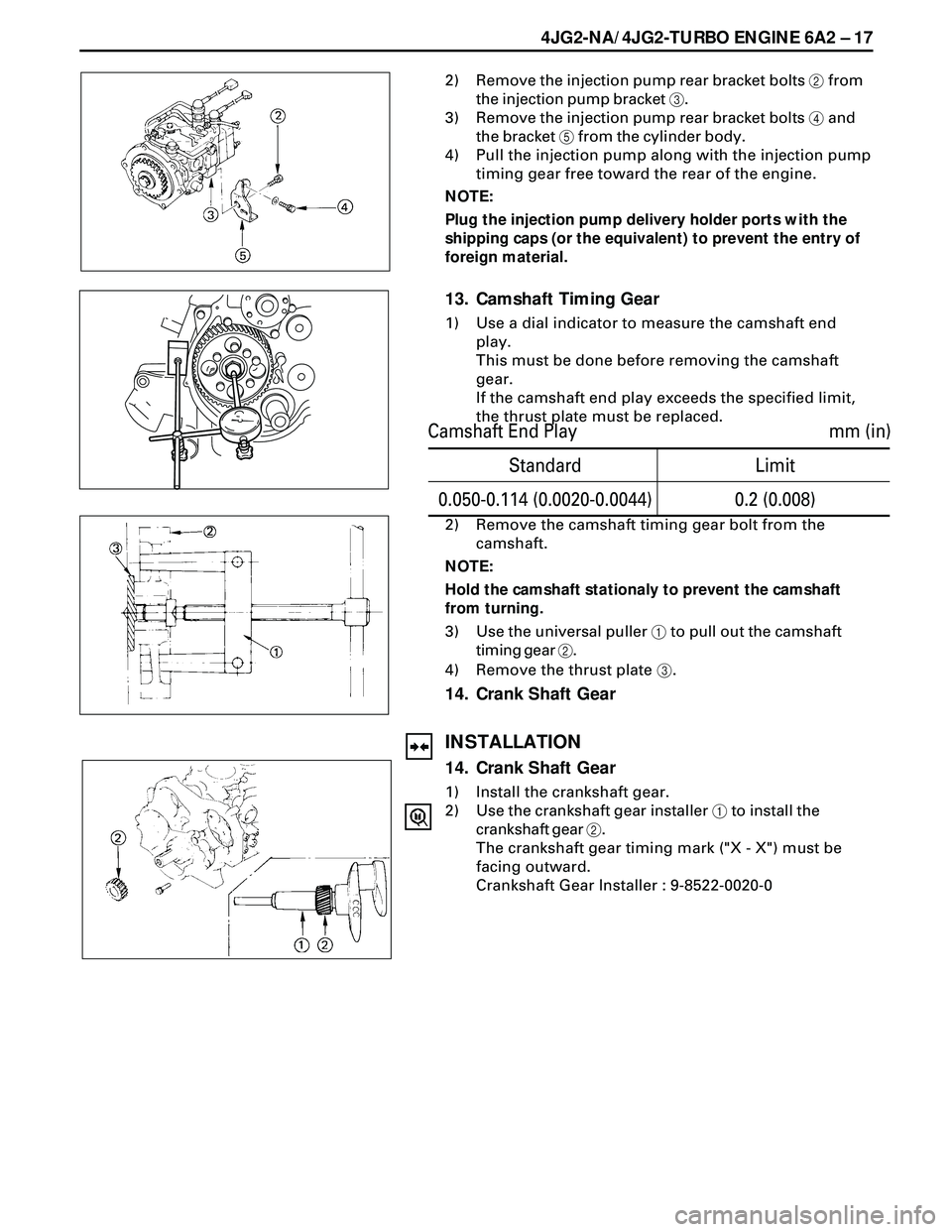
1) Remove the six injection pump bracket bolts 1 from
the timing gear case.
Standard
mm (in) Idler Gear End Play
0.07 (0.0028)Limit
0.2 (0.0079)
Page 1619 of 3573
4JG2-NA/4JG2-TURBO ENGINE 6A2 Ð 17
2) Remove the injection pump rear bracket bolts 2 from
the injection pump bracket 3.
3) Remove the injection pump rear bracket bolts 4 and
the bracket 5 from the cylinder body.
4) Pull the injection pump along with the injection pump
timing gear free toward the rear of the engine.
NOTE:
Plug the injection pump delivery holder ports with the
shipping caps (or the equivalent) to prevent the entry of
foreign material.
13. Camshaft Timing Gear
1) Use a dial indicator to measure the camshaft end
play.
This must be done before removing the camshaft
gear.
If the camshaft end play exceeds the specified limit,
the thrust plate must be replaced.
2) Remove the camshaft timing gear bolt from the
camshaft.
NOTE:
Hold the camshaft stationaly to prevent the camshaft
from turning.
3) Use the universal puller 1 to pull out the camshaft
timing gear 2.
4) Remove the thrust plate 3.
14. Crank Shaft Gear
INSTALLATION
14. Crank Shaft Gear
1) Install the crankshaft gear.
2) Use the crankshaft gear installer 1 to install the
crankshaft gear 2.
The crankshaft gear timing mark ("X - X") must be
facing outward.
Crankshaft Gear Installer : 9-8522-0020-0
Standard
mm (in) Camshaft End Play
0.050-0.114 (0.0020-0.0044)Limit
0.2 (0.008)
Page 1620 of 3573
6A2 Ð 18 4JG2-NA/4JG2-TURBO ENGINE
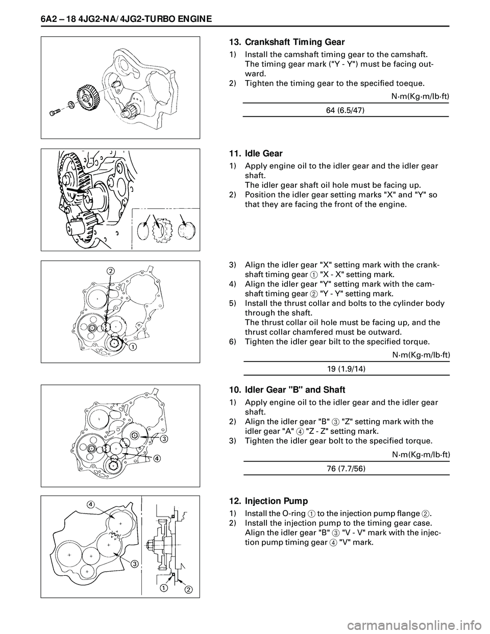
13. Crankshaft Timing Gear
1) Install the camshaft timing gear to the camshaft.
The timing gear mark ("Y - Y") must be facing out-
ward.
2) Tighten the timing gear to the specified toeque.
64 (6.5/47)N·m(Kg·m/lb·ft)
11. Idle Gear
1) Apply engine oil to the idler gear and the idler gear
shaft.
The idler gear shaft oil hole must be facing up.
2) Position the idler gear setting marks "X" and "Y" so
that they are facing the front of the engine.
3) Align the idler gear "X" setting mark with the crank-
shaft timing gear 1 "X - X" setting mark.
4) Align the idler gear "Y" setting mark with the cam-
shaft timing gear 2 "Y - Y" setting mark.
5) Install the thrust collar and bolts to the cylinder body
through the shaft.
The thrust collar oil hole must be facing up, and the
thrust collar chamfered must be outward.
6) Tighten the idler gear bilt to the specified torque.
19 (1.9/14)N·m(Kg·m/lb·ft)
10. Idler Gear "B" and Shaft
1) Apply engine oil to the idler gear and the idler gear
shaft.
2) Align the idler gear "B" 3 "Z" setting mark with the
idler gear "A" 4 "Z - Z" setting mark.
3) Tighten the idler gear bolt to the specified torque.
12. Injection Pump
1) Install the O-ring 1 to the injection pump flange 2.
2) Install the injection pump to the timing gear case.
Align the idler gear "B" 3 "V - V" mark with the injec-
tion pump timing gear 4 "V" mark.
76 (7.7/56)N·m(Kg·m/lb·ft)