relay ISUZU TROOPER 1998 Service Repair Manual
[x] Cancel search | Manufacturer: ISUZU, Model Year: 1998, Model line: TROOPER, Model: ISUZU TROOPER 1998Pages: 3573, PDF Size: 60.36 MB
Page 2598 of 3573
WIRING SYSTEM 8DÐ5
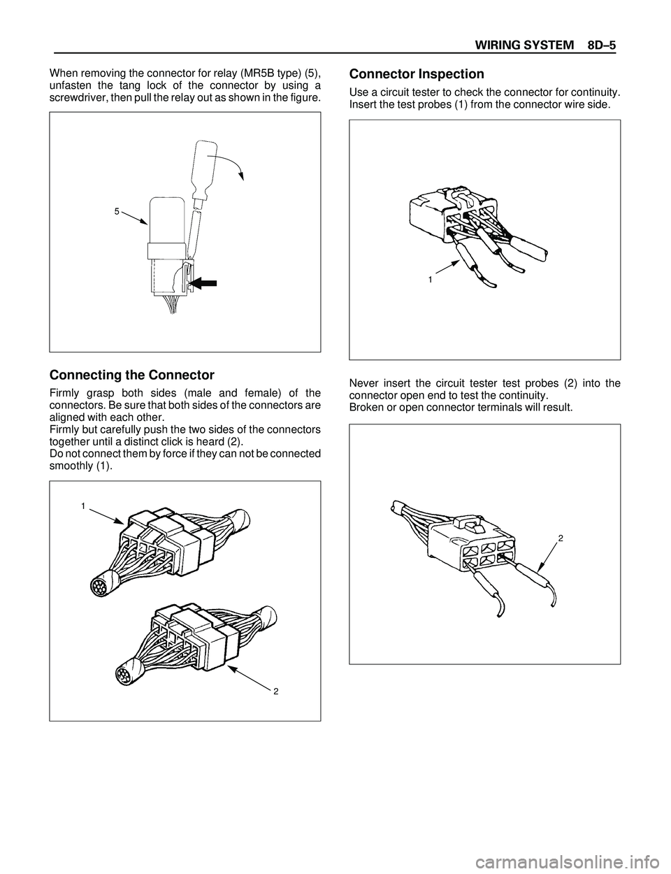
When removing the connector for relay (MR5B type) (5),
unfasten the tang lock of the connector by using a
screwdriver, then pull the relay out as shown in the figure.
Connecting the Connector
Firmly grasp both sides (male and female) of the
connectors. Be sure that both sides of the connectors are
aligned with each other.
Firmly but carefully push the two sides of the connectors
together until a distinct click is heard (2).
Do not connect them by force if they can not be connected
smoothly (1).
Connector Inspection
Use a circuit tester to check the connector for continuity.
Insert the test probes (1) from the connector wire side.
Never insert the circuit tester test probes (2) into the
connector open end to test the continuity.
Broken or open connector terminals will result.
5
1
2
1
2
Page 2603 of 3573
8DÐ10 WIRING SYSTEM
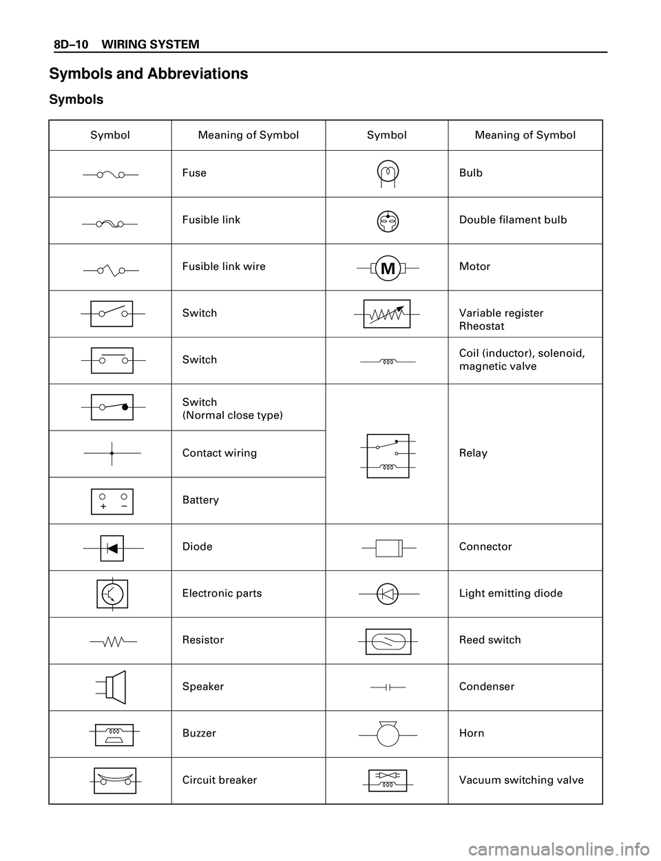
Symbols and Abbreviations
Symbols
Symbol Meaning of Symbol
Fuse
Fusible link
Fusible link wire
Switch
Switch
Contact wiring
Battery
Diode
Electronic parts
Resistor
Speaker
Buzzer
Circuit breakerSymbol Meaning of Symbol
Bulb
Double filament bulb
Motor
Variable register
Rheostat
Coil (inductor), solenoid,
magnetic valve
Relay
Connector
Light emitting diode
Reed switch
Condenser
Horn
Vacuum switching valve
+
–
Switch
(Normal close type)
M
Page 2609 of 3573
8DÐ16 WIRING SYSTEM
Circuit Breaker
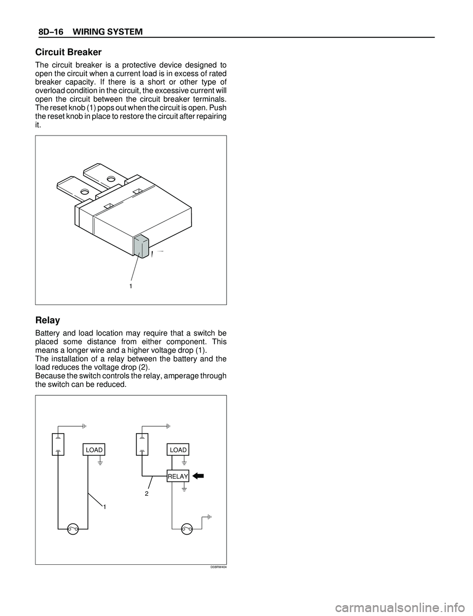
The circuit breaker is a protective device designed to
open the circuit when a current load is in excess of rated
breaker capacity. If there is a short or other type of
overload condition in the circuit, the excessive current will
open the circuit between the circuit breaker terminals.
The reset knob (1) pops out when the circuit is open. Push
the reset knob in place to restore the circuit after repairing
it.
Relay
Battery and load location may require that a switch be
placed some distance from either component. This
means a longer wire and a higher voltage drop (1).
The installation of a relay between the battery and the
load reduces the voltage drop (2).
Because the switch controls the relay, amperage through
the switch can be reduced.
Push
LOAD
12LOAD
RELAY
D08RW404
1
Page 2610 of 3573
WIRING SYSTEM 8DÐ17
Name/
ColorRated
voltage/Coil
resistanceInternal circuitName/
ColorRated
voltage/Coil
resistanceInternal circuit
1M
(MR5L)/
Black
12V/
Approx.
80W
Minimum
operating
voltage: 7V
at 77˚F (25˚C)2M
(MR5)/
Brown12V/
Approx.
80W
Minimum
operating
voltage: 7V
at 77˚F (25˚C)
1B
(MR5L)/
Grey1B-1M
(MR5)/
Grey
1M
(MR5)/
Black
(Case),
Blue
(Base)1M
1T
(MR5)/
Black/
Blue1M
(MR5B)/
BlackMinimum
operating
voltage: 9V
at 68˚F (20˚C)
12V
Minimum
operating
voltage:
4.3V at 77˚F
(25˚C)
1M
(Horn
relay)12V/
Minimum
operating
voltage: 8V
at 68˚F (20˚C)
Á À ÂÃ Á Ã
À
Â
Á À ÂÃ Á Ã
À
Â
Ä Ã ÀÂ
Â
ÀÃ
Ä
Ä Ã À
Â
Â
ÀÃ
Ä
Á
Á
ÁÂÀ
À
Á Â
Ä À
Ã
Ä
ÁÂ
ÅÀ
Â
Á
Ã
Å
Ä À
Ã
Ä
Á
Å
Â
À
ÁÃ ÅÂ
Á À ÂÃ
 ÃÀ Á
 À ÁÃ
Á Ã
À Â
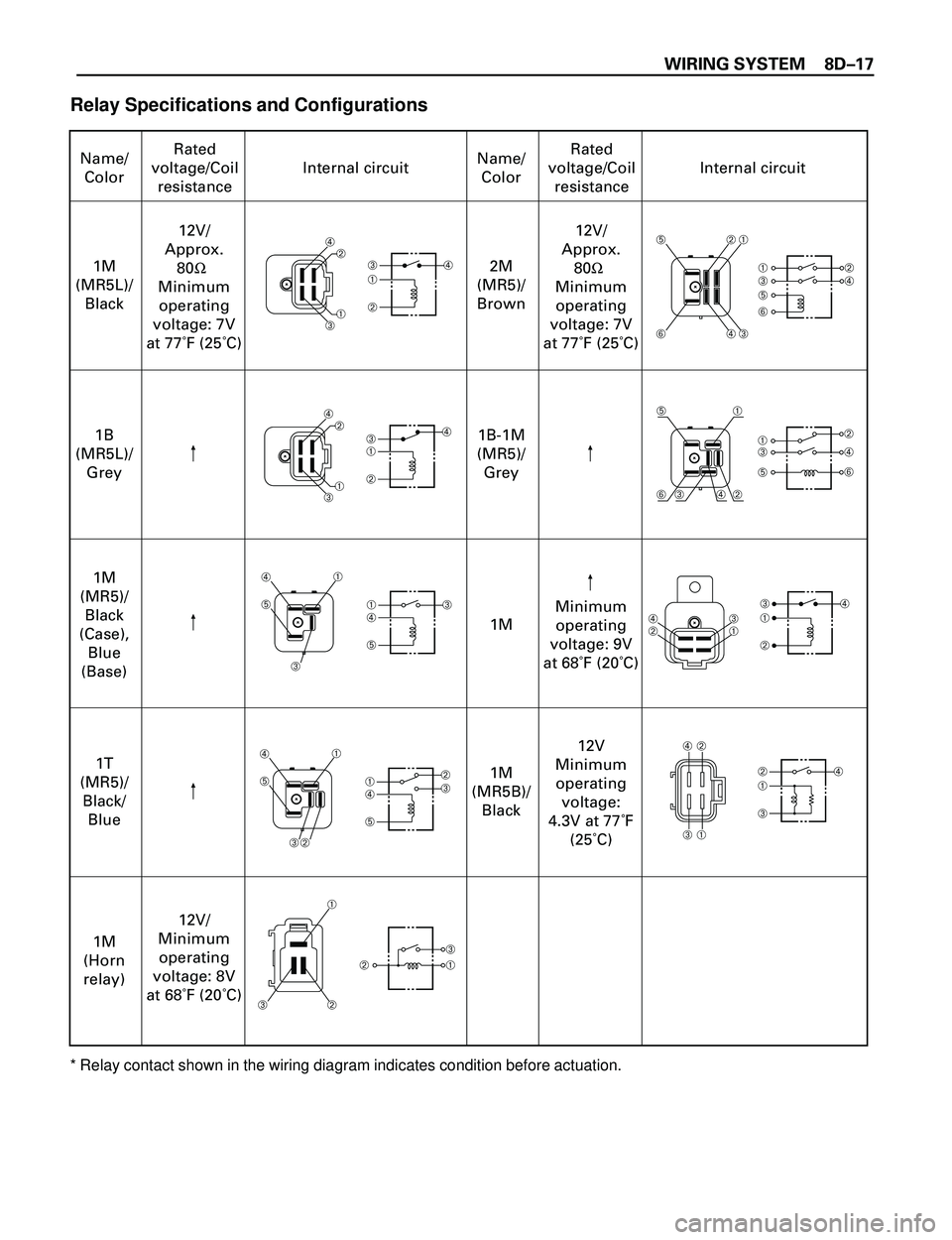
Relay Specifications and Configurations
* Relay contact shown in the wiring diagram indicates condition before actuation.
Page 2613 of 3573
8DÐ20 WIRING SYSTEM
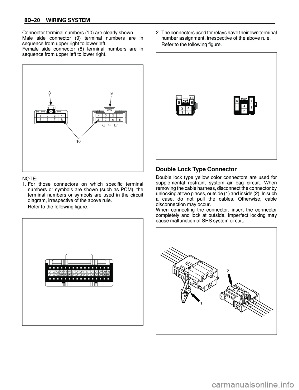
Connector terminal numbers (10) are clearly shown.
Male side connector (9) terminal numbers are in
sequence from upper right to lower left.
Female side connector (8) terminal numbers are in
sequence from upper left to lower right.
NOTE:
1. For those connectors on which specific terminal
numbers or symbols are shown (such as PCM), the
terminal numbers or symbols are used in the circuit
diagram, irrespective of the above rule.
Refer to the following figure.2. The connectors used for relays have their own terminal
number assignment, irrespective of the above rule.
Refer to the following figure.
Double Lock Type Connector
Double lock type yellow color connectors are used for
supplemental restraint systemÐair bag circuit. When
removing the cable harness, disconnect the connector by
unlocking at two places, outside (1) and inside (2). In such
a case, do not pull the cables. Otherwise, cable
disconnection may occur.
When connecting the connector, insert the connector
completely and lock at outside. Imperfect locking may
cause malfunction of SRS system circuit.
1234
56781 2 3 4
5 6 7 8
10 8
9
C1C2C3C4C5C6C7C8C9C10C11C12C13C14C15C16D1D2D3D4D5D6D7D8D9D10D11D12D13D14D15D162
1
24
136 5
65
1423
Page 2615 of 3573
8DÐ22 WIRING SYSTEM
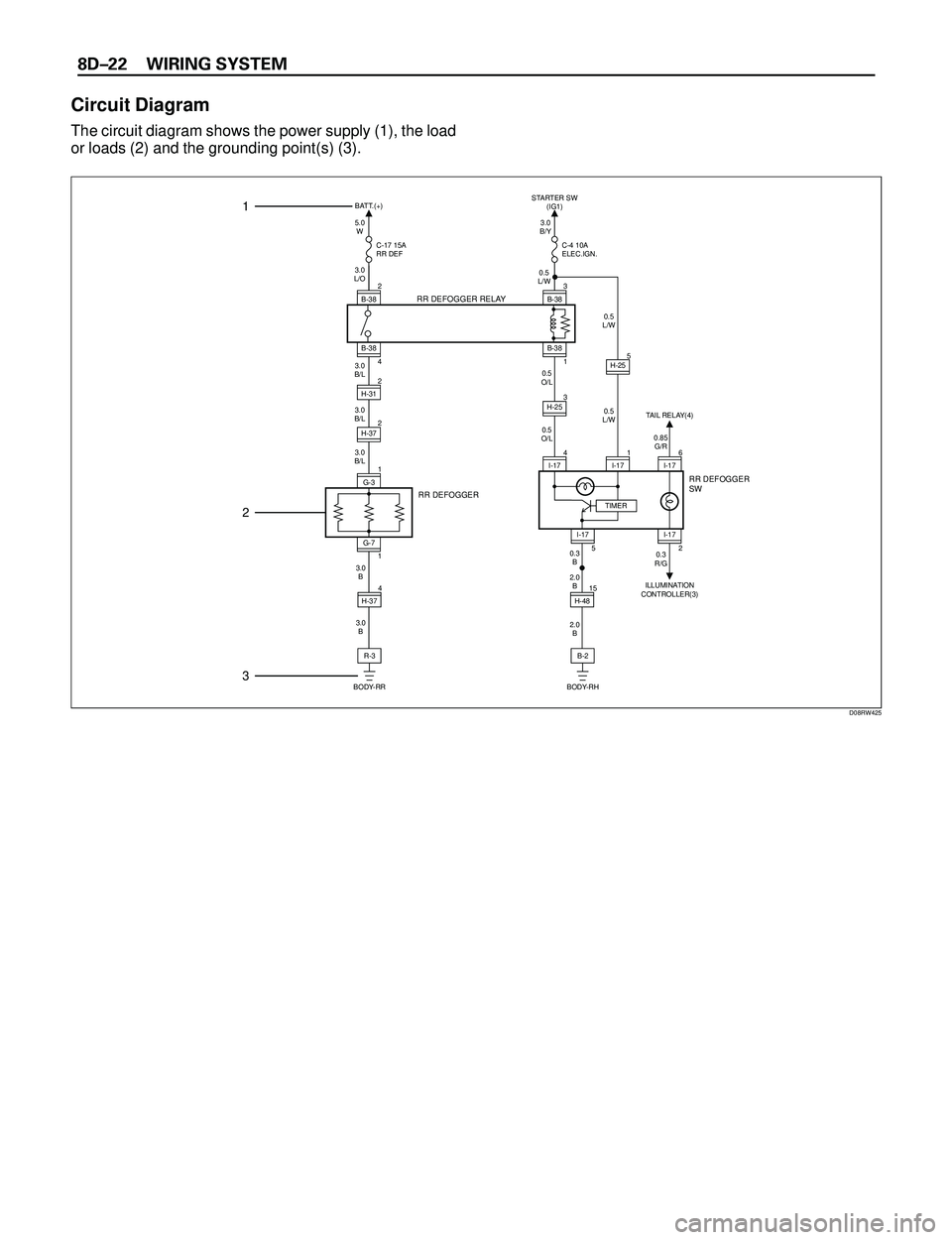
Circuit Diagram
The circuit diagram shows the power supply (1), the load
or loads (2) and the grounding point(s) (3).
5.0
W BATT.(+)
C-17 15A
RR DEF
RR DEFOGGER RELAY
3.0
L/O
3.0
B/L
3.0
B/L
3.0
B/L
B-38
4
I-17
5I-17
ILLUMINATION
CONTROLLER(3)
RR DEFOGGER
SW
RR DEFOGGER
2
H-37
G-7
1 2
B-38
2
2
H-31
1
G-3
3.0
B/Y
0.5
L/W
0.5
L/W
0.5
L/W 0.5
O/L
0.5
O/L STARTER SW
(IG1)
C-4 10A
ELEC.IGN.
3
B-38
4
I-17
15
H-48TIMER6
I-17 0.85
G/R TAIL RELAY(4)
B-38
1
H-253
H-255
1
I-17
B-2 2.0
B 3.0
B 3.0
B
2.0
B 0.3
B0.3
R/G
BODY-RHR-3
BODY-RR4
H-37
1
2
3
D08RW425
Page 2617 of 3573
8DÐ24 WIRING SYSTEM
12
D08RWA03
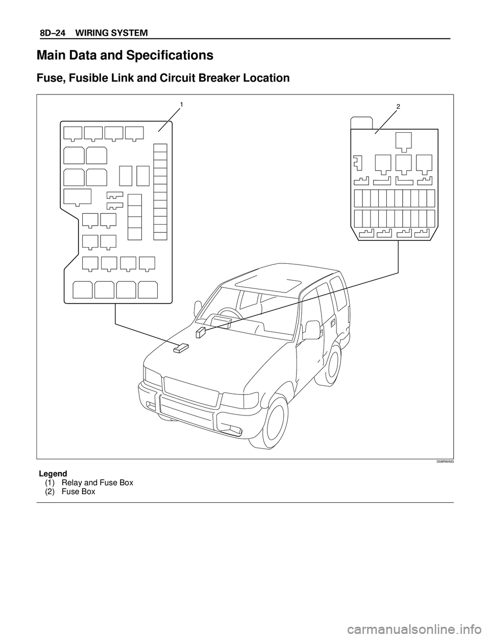
Legend
(1) Relay and Fuse Box
(2) Fuse Box
Main Data and Specifications
Fuse, Fusible Link and Circuit Breaker Location
Page 2618 of 3573
WIRING SYSTEM 8DÐ25
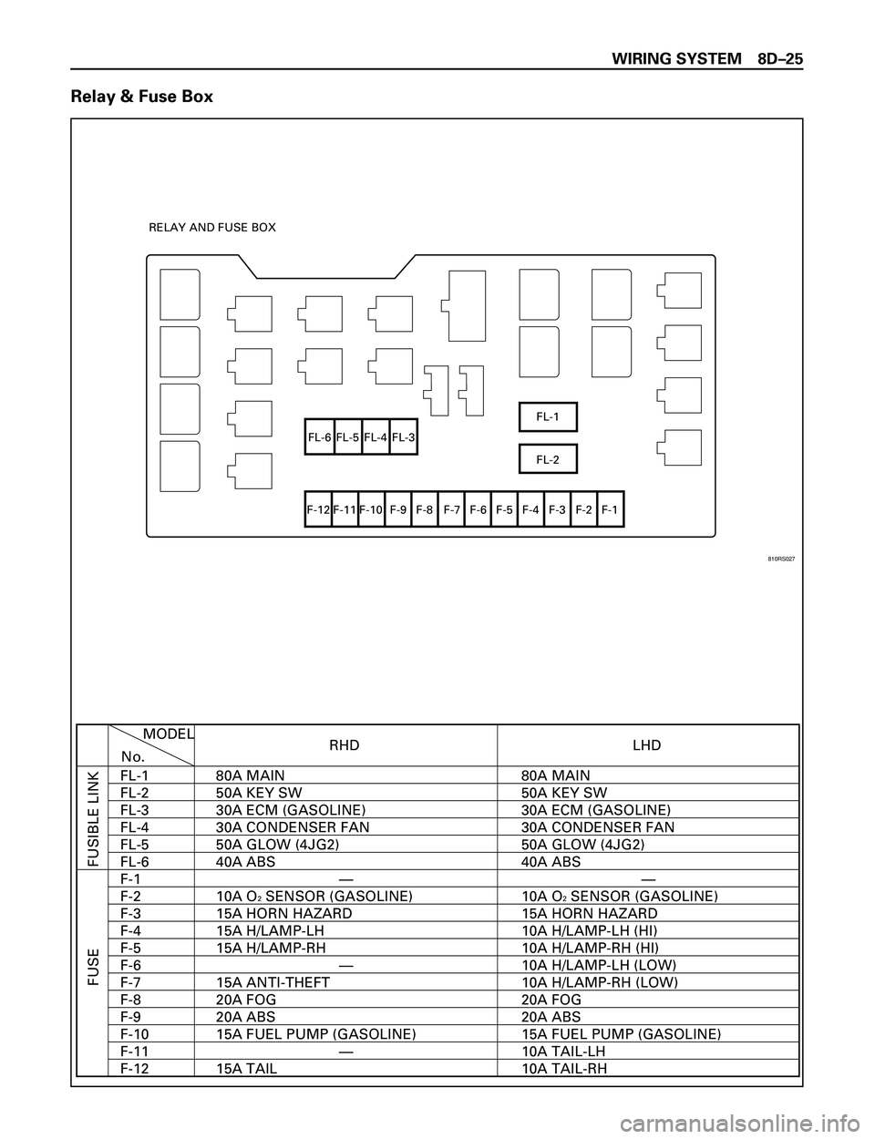
Relay & Fuse Box
FL-1
FL-2 FL-6 FL-5 FL-4 FL-3
F-12 F-11 F-10 F-9 F-8 F-7 F-6 F-5 F-4 F-3 F-2 F-1 RELAY AND FUSE BOX
RHD
FUSIBLE LINK FUSE
MODEL
No.
FL-1
FL-2
FL-3
FL-4
FL-5
FL-6
F-1
F-2
F-3
F-4
F-5
F-6
F-7
F-8
F-9
F-10
F-11
F-12LHD
80A MAIN
50A KEY SW
30A ECM (GASOLINE)
30A CONDENSER FAN
50A GLOW (4JG2)
40A ABS
10A O
2 SENSOR (GASOLINE)
15A HORN HAZARD
15A H/LAMP-LH
15A H/LAMP-RH
15A ANTI-THEFT
20A FOG
20A ABS
15A FUEL PUMP (GASOLINE)
15A TAIL80A MAIN
50A KEY SW
30A ECM (GASOLINE)
30A CONDENSER FAN
50A GLOW (4JG2)
40A ABS
10A O2 SENSOR (GASOLINE)
15A HORN HAZARD
10A H/LAMP-LH (HI)
10A H/LAMP-RH (HI)
10A H/LAMP-LH (LOW)
10A H/LAMP-RH (LOW)
20A FOG
20A ABS
15A FUEL PUMP (GASOLINE)
10A TAIL-LH
10A TAIL-RH —
—
——
810RS027
Page 2619 of 3573
8DÐ26 WIRING SYSTEM
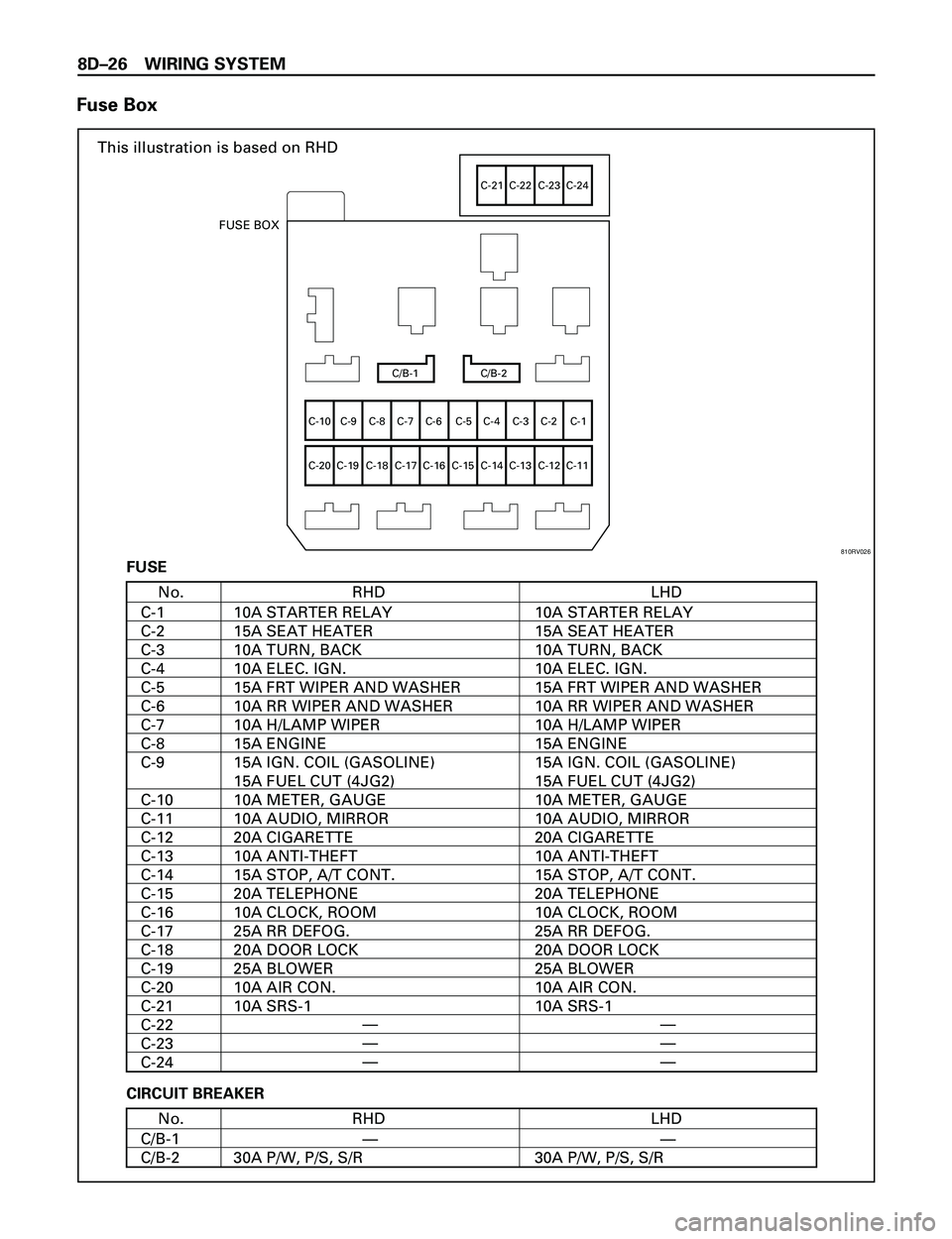
Fuse Box
This illustration is based on RHD
C/B-1 C/B-2
C-10
C-20C-9 C-8 C-7 C-6 C-5 C-4 C-3 C-2 C-1
C-19 C-18 C-17 C-16 C-15 C-14 C-13 C-12 C-11
C-21 C-22 C-23 C-24
FUSE BOX
RHDNo.
C-1
C-2
C-3
C-4
C-5
C-6
C-7
C-8
C-9
C-10
C-11
C-12
C-13
C-14
C-15
C-16
C-17
C-18
C-19
C-20
C-21
C-22
C-23
C-24LHD
10A STARTER RELAY
15A SEAT HEATER
10A TURN, BACK
10A ELEC. IGN.
15A FRT WIPER AND WASHER
10A RR WIPER AND WASHER
10A H/LAMP WIPER
15A ENGINE
15A IGN. COIL (GASOLINE)
15A FUEL CUT (4JG2)
10A METER, GAUGE
10A AUDIO, MIRROR
20A CIGARETTE
10A ANTI-THEFT
15A STOP, A/T CONT.
20A TELEPHONE
10A CLOCK, ROOM
25A RR DEFOG.
20A DOOR LOCK
25A BLOWER
10A AIR CON.
10A SRS-110A STARTER RELAY
15A SEAT HEATER
10A TURN, BACK
10A ELEC. IGN.
15A FRT WIPER AND WASHER
10A RR WIPER AND WASHER
10A H/LAMP WIPER
15A ENGINE
15A IGN. COIL (GASOLINE)
15A FUEL CUT (4JG2)
10A METER, GAUGE
10A AUDIO, MIRROR
20A CIGARETTE
10A ANTI-THEFT
15A STOP, A/T CONT.
20A TELEPHONE
10A CLOCK, ROOM
25A RR DEFOG.
20A DOOR LOCK
25A BLOWER
10A AIR CON.
10A SRS-1 FUSE
RHDNo.
C/B-1
C/B-2LHD
30A P/W, P/S, S/R 30A P/W, P/S, S/R—— CIRCUIT BREAKER
—
—
——
—
—
810RV026
Page 2620 of 3573
WIRING SYSTEM 8DÐ27
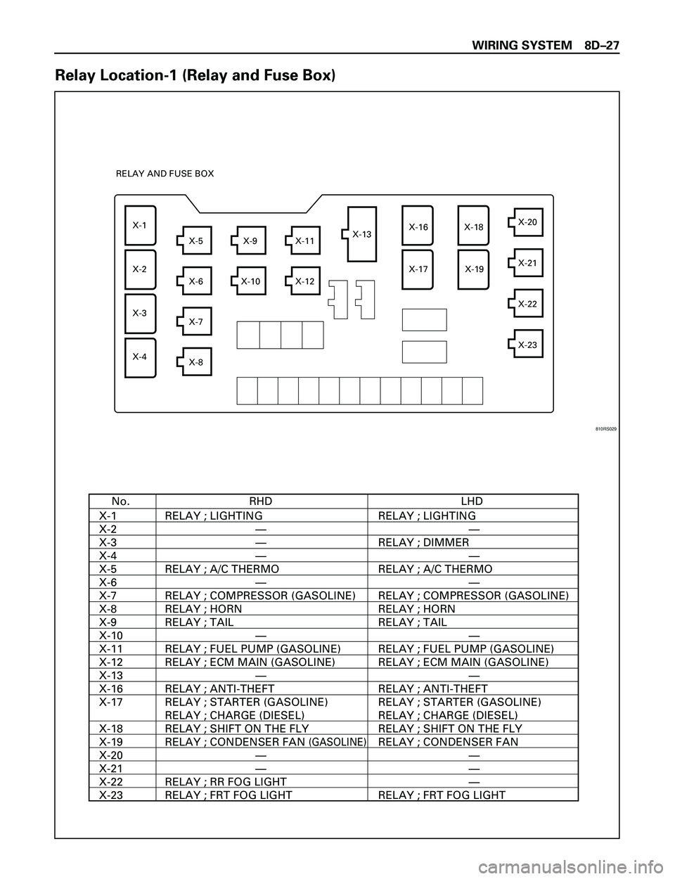
Relay Location-1 (Relay and Fuse Box)
RHDNo.
X-1
X-2
X-3
X-4
X-5
X-6
X-7
X-8
X-9
X-10
X-11
X-12
X-13
X-16
X-17
X-18
X-19
X-20
X-21
X-22
X-23LHD
RELAY ; LIGHTING
RELAY ; A/C THERMO
RELAY ; COMPRESSOR (GASOLINE)
RELAY ; HORN
RELAY ; TAIL
RELAY ; FUEL PUMP (GASOLINE)
RELAY ; ECM MAIN (GASOLINE)
RELAY ; ANTI-THEFT
RELAY ; STARTER (GASOLINE)
RELAY ; CHARGE (DIESEL)
RELAY ; SHIFT ON THE FLY
RELAY ; CONDENSER FAN
(GASOLINE)
RELAY ; RR FOG LIGHT
RELAY ; FRT FOG LIGHTRELAY ; LIGHTING
RELAY ; DIMMER
RELAY ; A/C THERMO
RELAY ; COMPRESSOR (GASOLINE)
RELAY ; HORN
RELAY ; TAIL
RELAY ; FUEL PUMP (GASOLINE)
RELAY ; ECM MAIN (GASOLINE)
RELAY ; ANTI-THEFT
RELAY ; STARTER (GASOLINE)
RELAY ; CHARGE (DIESEL)
RELAY ; SHIFT ON THE FLY
RELAY ; CONDENSER FAN
RELAY ; FRT FOG LIGHT
—
—
—
—
—
—
—
——
—
—
—
—
—
—
—
X-1
X-2
X-3
X-4X-5
X-6
X-7
X-8X-9
X-10 X-12X-11X-13X-16
X-17X-18
X-19X-20
X-21
X-22
X-23 RELAY AND FUSE BOX
810RS029