ISUZU TROOPER 1998 Service Repair Manual
Manufacturer: ISUZU, Model Year: 1998, Model line: TROOPER, Model: ISUZU TROOPER 1998Pages: 3573, PDF Size: 60.36 MB
Page 211 of 3573
AIR CONDITIONING 1BÐ85
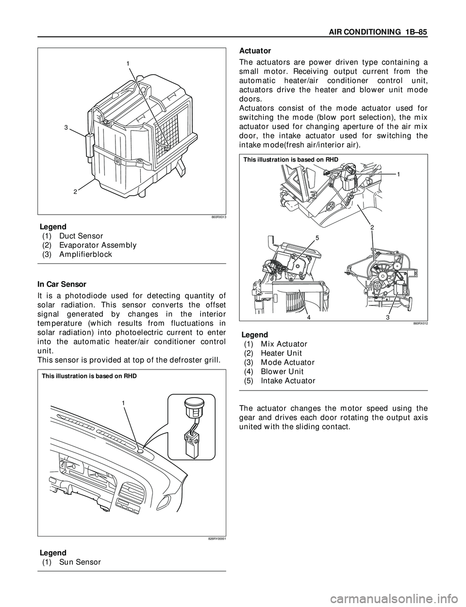
Legend
(1) Duct Sensor
(2) Evaporator Assembly
(3) Amplifierblock
In Car Sensor
It is a photodiode used for detecting quantity of
solar radiation. This sensor converts the offset
signal generated by changes in the interior
temperature (which results from fluctuations in
solar radiation) into photoelectric current to enter
into the automatic heater/air conditioner control
unit.
This sensor is provided at top of the defroster grill.
Legend
(1) Sun SensorActuator
The actuators are power driven type containing a
small motor. Receiving output current from the
automatic heater/air conditioner control unit,
actuators drive the heater and blower unit mode
doors.
Actuators consist of the mode actuator used for
switching the mode (blow port selection), the mix
actuator used for changing aperture of the air mix
door, the intake actuator used for switching the
intake mode(fresh air/interior air).
Legend
(1) Mix Actuator
(2) Heater Unit
(3) Mode Actuator
(4) Blower Unit
(5) Intake Actuator
The actuator changes the motor speed using the
gear and drives each door rotating the output axis
united with the sliding contact.
2 31
860RX013
1
826RY00001
This illustration is based on RHD
2
5
431
860RX012
This illustration is based on RHD
Page 212 of 3573
1BÐ86 AIR CONDITIONING
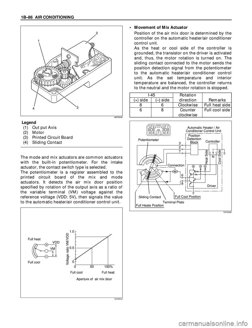
Legend
(1) Out put Axis
(2) Motor
(3) Printed Circuit Board
(4) Sliding Contact
The mode and mix actuators are common actuators
with the built-in potentiometer. For the intake
actuator, the contact switch type is selected.
The potentiometer is a register assembled to the
printed circuit board of the mix and mode
actuators. It detects the air mix door position
specified by rotation of the output axis as a ratio of
the variable terminal (VM) voltage against the
reference voltage (VDD: 5V), then signals the value
to the automatic heater/air conditioner control unit.¥ Movement of Mix Actuator
Position of the air mix door is determined by the
controller on the automatic heater/air conditioner
control unit.
As the heat or cool side of the controller is
grounded, the transistor on the driver is activated
and, thus, the motor rotation is turned on. The
sliding contact connected to the motor sends the
position detection signal from the potentiometer
to the automatic heater/air conditioner control
unit. As the set temperature and interior
temperature are balanced, the controller returns
to the neutral and the motor rotation is stopped.
12
43
860RW026
C01RX016
M
N 3
2
7
6
8
98 43
65 21
7
Potentiometer
ConnectionPosition
Detection
Block Automatic Heater / Air
Conditioner Control Unit
Controller
Sliding Contact
Full Heate PositionTerminal PlateFull Cool PositionDriver
Cool Side Heat Side
C01RX005
Full cool
Full cool0 0 0.5 1.0
50 100%
Aperture of air mix doorVoltage ratio VM/VDD
Full heat Full heat
VDD
VM +
–
I-45 Rotation
(+) side (Ð) side direction Remarks
8 6 Clockwise Full heat side
6 8 Counter Full cool side
clockwise
Page 213 of 3573
AIR CONDITIONING 1BÐ87
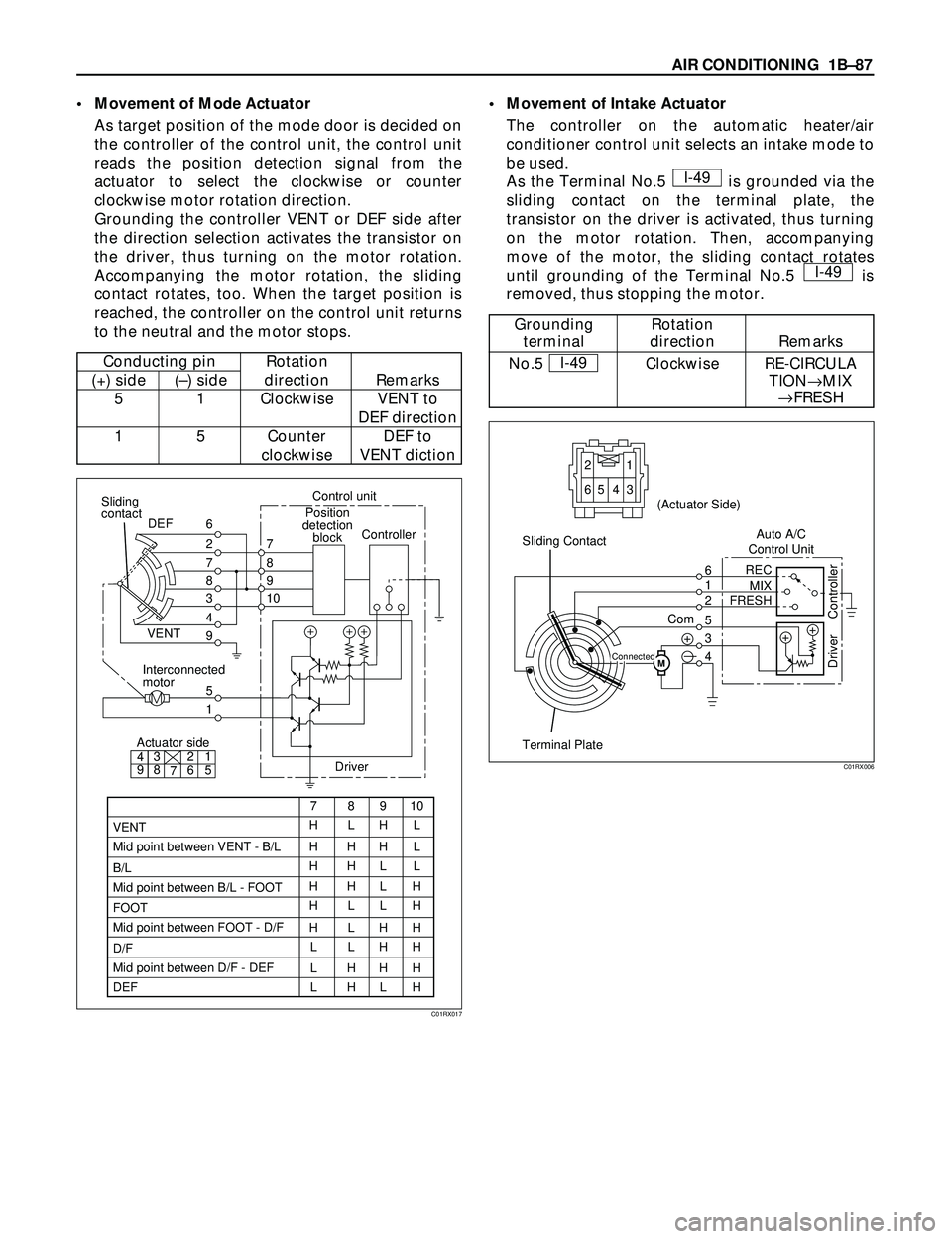
¥ Movement of Mode Actuator
As target position of the mode door is decided on
the controller of the control unit, the control unit
reads the position detection signal from the
actuator to select the clockwise or counter
clockwise motor rotation direction.
Grounding the controller VENT or DEF side after
the direction selection activates the transistor on
the driver, thus turning on the motor rotation.
Accompanying the motor rotation, the sliding
contact rotates, too. When the target position is
reached, the controller on the control unit returns
to the neutral and the motor stops.¥ Movement of Intake Actuator
The controller on the automatic heater/air
conditioner control unit selects an intake mode to
be used.
As the Terminal No.5 is grounded via the
sliding contact on the terminal plate, the
transistor on the driver is activated, thus turning
on the motor rotation. Then, accompanying
move of the motor, the sliding contact rotates
until grounding of the Terminal No.5 is
removed, thus stopping the motor.I-49
I-49
DriverController
DEF side
VENT
side
Position
detection
block Control unit
Sliding
contact
Actuator side42
983
7
78910
HLHL
HHHL
HHLL
HHLH
HLLH
HLHH
LLHH
LHHH
LHLH 61
5
Interconnected
motor
VENTVENT
Mid point between VENT - B/L
B/L
Mid point between B/L - FOOT
FOOT
Mid point between FOOT - D/F
D/F
Mid point between D/F - DEF
DEFDEF
7
8
9
10 2 6
7
8
3
4
9
5
1
C01RX017
M
+6 1 2
65 4 3
REC
MIX
FRESH
Com1
2
5
3
4++
Ð
Terminal PlateAuto A/C
Control Unit (Actuator Side)
Driver Controller
Sliding Contact
Connected
C01RX006
Conducting pin Rotation
(+) side (Ð) side direction Remarks
5 1 Clockwise VENT to
DEF direction
1 5 Counter DEF to
clockwise VENT diction
Grounding Rotation
terminal direction Remarks
No.5 Clockwise RE-CIRCULA
TION
®MIX
®FRESH I-49
Page 214 of 3573

1BÐ88 AIR CONDITIONING
OVERVIEW OF AUTOMATIC CONTROL OF
FULL AUTOMATIC AIR CONDITIONER
The full automatic heater and air conditioner on this
vehicle has the following features:
¥ Interior temperature control.
¥ Air flow control.
¥ Mode (blow port) control.
¥ Intake (switching between fresh air and interior
air) control.
¥ Heater start timing control.
¥ Cooler start timing control.
¥ Evaporator anti-freeze control.
1. Interior Temperature Control
The automatic heater/air conditioner control unit
operates on the setup temperature signal from
the temperature control switch and other sensor
signals to derive the total signal. Then, the
control unit compares this signal against the
signal from the potentiometer to determine
rotation direction of the mix actuator. The mix
actuator moves the air mix door to the aperture
specified by the total signal so that the specified
interior temperature is achieved.
If the compressor is turned off in the A/C (air
conditioning) mode, aperture of the air mix door
is offset according to the outside air temperature
or the specified interior temperature. This
function removes the difference in the blowing
temperature in this state and that of when the
compressor is turned on.
When FH or FC is selected for the setup
temperature, the air mix door is accordingly
fixed to the Full Heat or Full Cool mode.
When the VENT mode is selected, aperture of
the air mix door is controlled so that excessively
heated air may not be blown from the VENT
blow port.
0 50
140 104 68 32
Air mix door aperture
Full cool
Heater
side Restriction on the
aperture enabied
in the VENT modeAir conditioning
ON mode Full heatSet temperature
signal
Mix
actuator
Potentio
meter
Air mix door
In car sensor
Ambient sensor
Sun sensor
Control unitAir conditioning
switch
Set up temperature
signal
Air conditioning
OFF mode
Total signal Cooler
side
C01RY00011
Page 215 of 3573
AIR CONDITIONING 1BÐ89
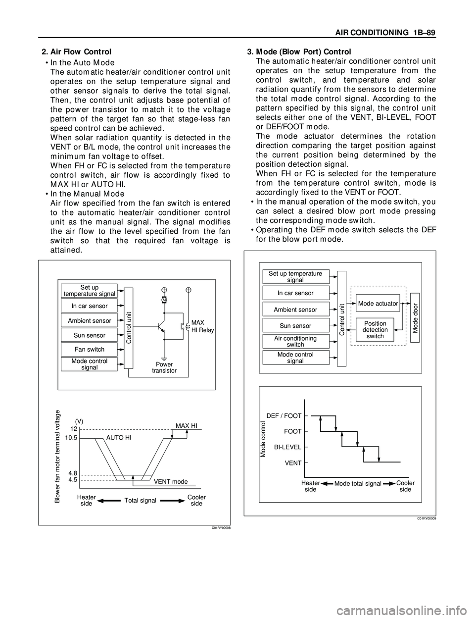
2. Air Flow Control
¥ In the Auto Mode
The automatic heater/air conditioner control unit
operates on the setup temperature signal and
other sensor signals to derive the total signal.
Then, the control unit adjusts base potential of
the power transistor to match it to the voltage
pattern of the target fan so that stage-less fan
speed control can be achieved.
When solar radiation quantity is detected in the
VENT or B/L mode, the control unit increases the
minimum fan voltage to offset.
When FH or FC is selected from the temperature
control switch, air flow is accordingly fixed to
MAX HI or AUTO HI.
¥ In the Manual Mode
Air flow specified from the fan switch is entered
to the automatic heater/air conditioner control
unit as the manual signal. The signal modifies
the air flow to the level specified from the fan
switch so that the required fan voltage is
attained.3. Mode (Blow Port) Control
The automatic heater/air conditioner control unit
operates on the setup temperature from the
control switch, and temperature and solar
radiation quantify from the sensors to determine
the total mode control signal. According to the
pattern specified by this signal, the control unit
selects either one of the VENT, BI-LEVEL, FOOT
or DEF/FOOT mode.
The mode actuator determines the rotation
direction comparing the target position against
the current position being determined by the
position detection signal.
When FH or FC is selected for the temperature
from the temperature control switch, mode is
accordingly fixed to the VENT or FOOT.
¥ In the manual operation of the mode switch, you
can select a desired blow port mode pressing
the corresponding mode switch.
¥ Operating the DEF mode switch selects the DEF
for the blow port mode.
4.512
(V)
M
MAX
HI Relay
Power
transistor
4.8 10.5MAX HI Set up
temperature signal
Control unit
In car sensor
Ambient sensor
Sun sensor
Mode control
signal Fan switch
AUTO HI
Heater
sideCooler
side Total signalVENT mode
Blower fan motor terminal voltage
C01RY00008
Mode control
DEF / FOOTSet up temperature
signal
Mode actuator
Mode doorPosition
detection
switch
Control unit
In car sensor
Sun sensor
Air conditioning
switch
Mode control
signal Ambient sensor
FOOT
BI-LEVEL
VENT
Heater
sideCooler
side Mode total signal
C01RY00009
Page 216 of 3573
1BÐ90 AIR CONDITIONING
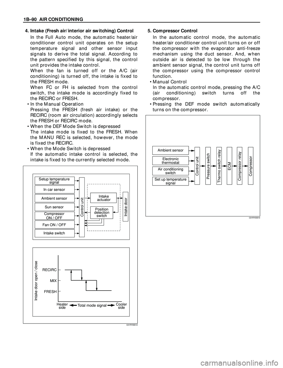
4. Intake (Fresh air/interior air switching) Control
In the Full Auto mode, the automatic heater/air
conditioner control unit operates on the setup
temperature signal and other sensor input
signals to derive the total signal. According to
the pattern specified by this signal, the control
unit provides the intake control.
When the fan is turned off or the A/C (air
conditioning) is turned off, the intake is fixed to
the FRESH mode.
When FC or FH is selected from the control
switch, the intake mode is accordingly fixed to
the RECIRC or FRESH.
¥ In the Manual Operation
Pressing the FRESH (fresh air intake) or the
RECIRC (room air circulation) accordingly selects
the FRESH or RECIRC mode.
¥ When the DEF Mode Switch is depressed
The intake mode is fixed to the FRESH. When
the MANU REC is selected, however, the mode
is fixed the RECIRC.
¥ When the Mode Switch is depressed
If the automatic intake control is selected, the
intake is fixed to the currently selected mode.5. Compressor Control
In the automatic control mode, the automatic
heater/air conditioner control unit turns on or off
the compressor with the evaporator anti-freeze
mechanism using the duct sensor. And, when
outside air is detected to be low through the
ambient sensor signal, the control unit turns off
the compressor using the compressor control
function.
¥ Manual Control
In the automatic control mode, pressing the A/C
(air conditioning) switch turns off the
compressor.
¥ Pressing the DEF mode switch automatically
turns on the compressor.
Intake door open / close
RECIRC Setup temperature
signal
Intake
actuator
Position
detection
switch
In car sensor
Ambient sensor
Sun sensor
Compressor
ON / OFF
Fan ON / OFF
Intake switch
Control unit
Intake door
MIX
FRESH
Heater
sideCooler
side Total mode signal
C01RY00012
Ambient sensor
Control unit
Pressure switch
Thermo switch relay
ECM
Compressor relay
Compressor
Electronic
thermostat
Air conditioning
switch
Set up temperature
signal
C01RY00010
Page 217 of 3573
AIR CONDITIONING 1BÐ91
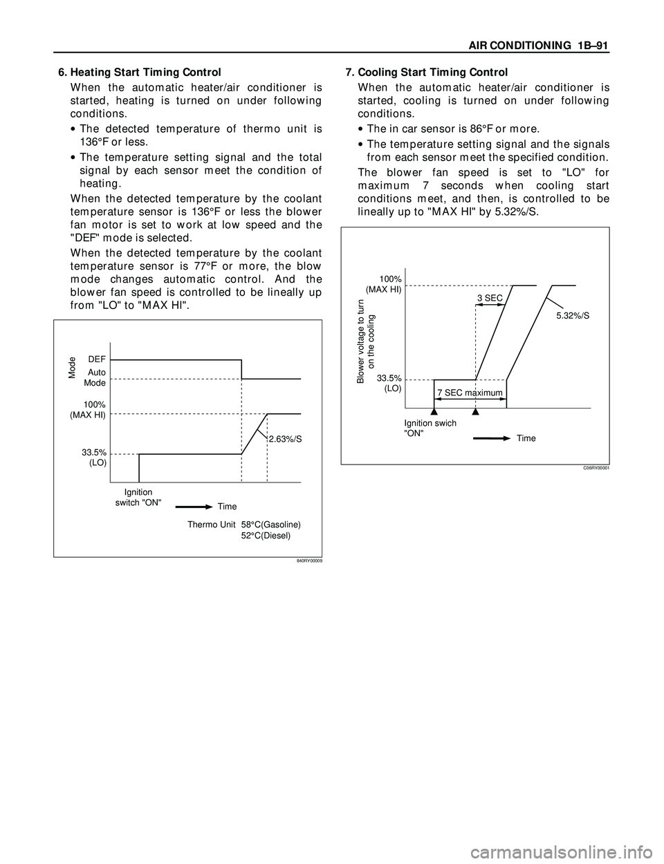
6. Heating Start Timing Control
When the automatic heater/air conditioner is
started, heating is turned on under following
conditions.
·The detected temperature of thermo unit is
136¡F or less.
·The temperature setting signal and the total
signal by each sensor meet the condition of
heating.
When the detected temperature by the coolant
temperature sensor is 136¡F or less the blower
fan motor is set to work at low speed and the
"DEF" mode is selected.
When the detected temperature by the coolant
temperature sensor is 77¡F or more, the blow
mode changes automatic control. And the
blower fan speed is controlled to be lineally up
from "LO" to "MAX HI".7. Cooling Start Timing Control
When the automatic heater/air conditioner is
started, cooling is turned on under following
conditions.
·The in car sensor is 86¡F or more.
·The temperature setting signal and the signals
from each sensor meet the specified condition.
The blower fan speed is set to "LO" for
maximum 7 seconds when cooling start
conditions meet, and then, is controlled to be
lineally up to "MAX HI" by 5.32%/S.
Ignition swich
"ON"
Time
Blower voltage to turn
on the cooling
7 SEC maximum3 SEC
100%
(MAX HI)
33.5%
(LO)5.32%/S
C06RY00001
33.5%
(LO)
2.63%/S
Mode
DEF
Auto
Mode
100%
(MAX HI)
Ignition
switch "ON"
Thermo Unit 58¡C(Gasoline)
52¡C(Diesel) Time
840RY00009
Page 218 of 3573

1BÐ92 AIR CONDITIONING
TROUBLESHOOTING
Troubleshooting, Its Overview and Procedures
The full automatic heater and air conditioner equips with the "Self-Diagnosis Function" to check its major
components.
This function makes access to the sensors, actuators and blower fan motor system easier when checking
them up and, when a failed part is located, this function restores its original performance.
When implementing the troubleshooting, this self-diagnosis function narrows the range to be searched at
the first step, then check relevant parts one by one according to the "Checking Procedures by Failed
Location" As for a location this function is unappreciable, the system accurately determines characteristics
of a given trouble and checks relevant parts according to the "Checking Procedures by Failed Location".
The following illustrates basic troubleshooting flow.
1. Basic Troubleshooting Flow
Occurrence of a trouble
Refer to the check list for
the inspection.Locate the failed location.
Check the failed part.
Correction
Correction
Correction
Troubleshooting by the
self-diagnosis function.Reference the "Check
Procedure by Failed
Location" for the inspection.
Reference the "Check
Procedure by Failed
Location" for the inspection.Correction
Check the cooling / heating
cycles.
End OK OK OK OKNG
NG
NG
NG
NG OK
Check if the automatic
heater / air conditioner
control unit indicator LED
is turned on.Check the power supply and
circuit on the automatic
heater / air conditioner control
unit.
Troubleshooting not relying
on the self-diagnosis
function(troubleshooting
by failure type).
F01RX009
Page 219 of 3573
AIR CONDITIONING 1BÐ93
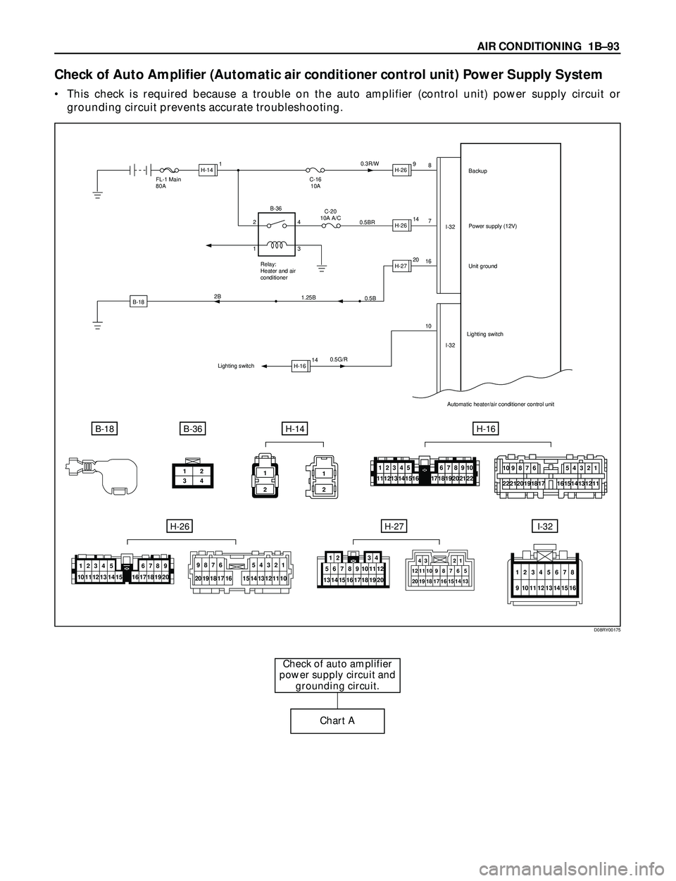
Check of Auto Amplifier (Automatic air conditioner control unit) Power Supply System
¥ This check is required because a trouble on the auto amplifier (control unit) power supply circuit or
grounding circuit prevents accurate troubleshooting.
Check of auto amplifier
power supply circuit and
grounding circuit.
Chart A
B-18
FL-1 Main
80A
0.5G/R16
107 8
I-32
I-32 C-16
10A0.3R/W
0.5BRBackup
Power supply (12V)
Unit ground
Automatic heater/air conditioner control unit
B-18B-36H-14
C-20
10A A/C
Relay:
Heater and air
conditioner
0.5B
1.25B 2B
Lighting switchLighting switch
H-141H-269
H-2614
H-2720
H-1614 2
14
3 B-36
12
34
H-16
H-26H-27I-32
1
2
1
2
10987654321
222120191815141312111716
12345111213141567891018192021221617
10 11 12 13 14 151234 5
17 18 19 206789
16
9876
20 19 18 17 165
14 154
133
122
111
10
20 12
19 11
18 10
179
168
157
146
13512 34
43 21
12111098765
13 14 15 16 17 18 19 20
12345678
9 10111213141516
D08RY00175
Page 220 of 3573
1BÐ94 AIR CONDITIONING
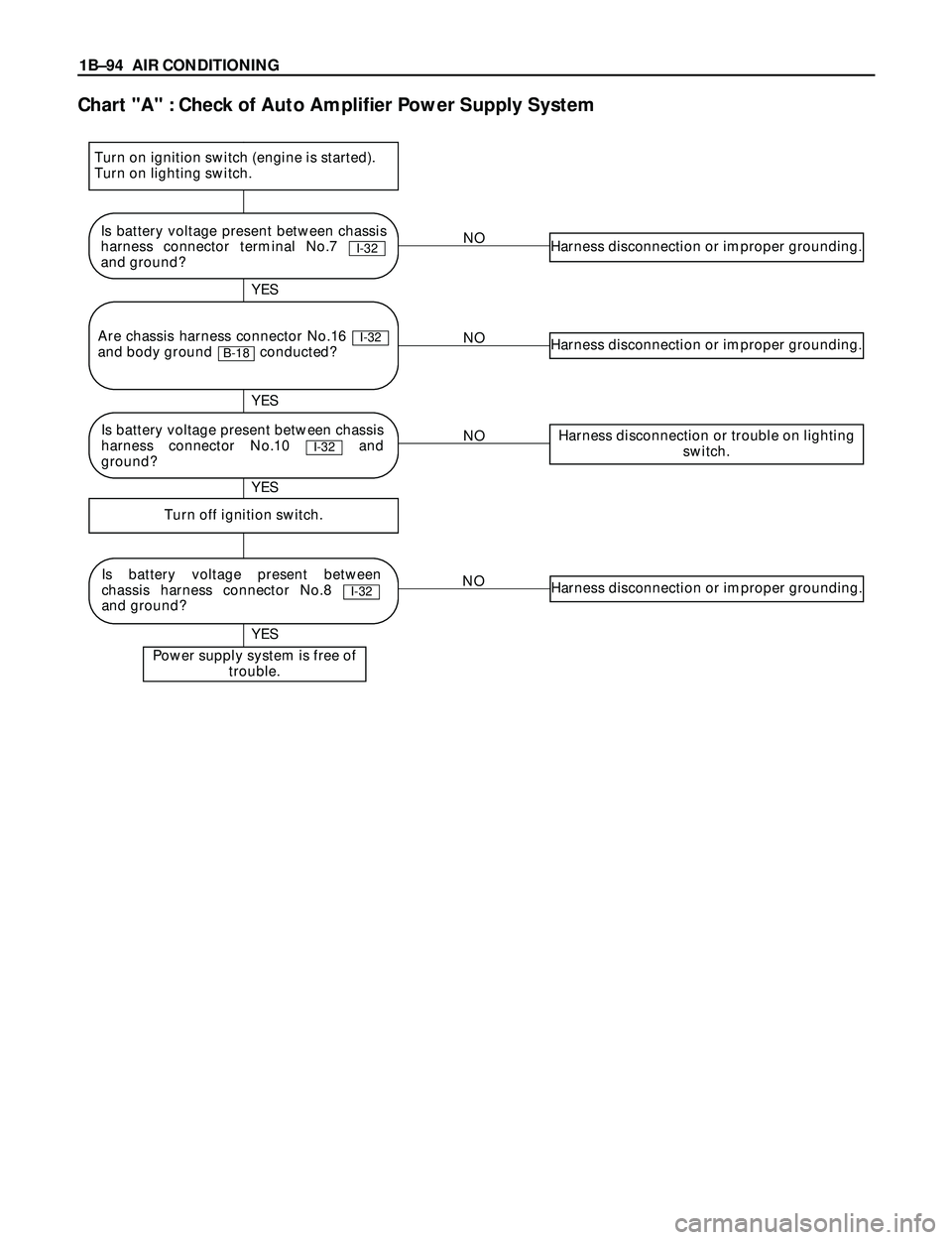
Chart "A" : Check of Auto Amplifier Power Supply System
NOHarness disconnection or improper grounding.
NOHarness disconnection or improper grounding.
NOHarness disconnection or trouble on lighting
switch.
NOHarness disconnection or improper grounding.
Turn off ignition switch.
Power supply system is free of
trouble.
YES YES
YES YES
Is battery voltage present between chassis
harness connector terminal No.7
and ground?
I-32
Is battery voltage present between
chassis harness connector No.8
and ground?
I-32
Are chassis harness connector No.16
and body ground conducted?
B-18I-32
Turn on ignition switch (engine is started).
Turn on lighting switch.
Is battery voltage present between chassis
harness connector No.10 and
ground?
I-32