ISUZU TROOPER 1998 Service Repair Manual
TROOPER 1998
ISUZU
ISUZU
https://www.carmanualsonline.info/img/61/57184/w960_57184-0.png
ISUZU TROOPER 1998 Service Repair Manual
Page 2998 of 3573

WIRING SYSTEM 8DÐ405
TERMINAL
CONNECTIONCHECK
OPERATIONCIRCUIT
NO. ITEM CONDITION
1 FRT door switchÐLH, RH ContinuityOpen door Continuity
Close door No continuity
2 RR door switchÐLH, RH ContinuityOpen door Continuity
Close door No continuity
3Ñ Ñ Ð Ð
4 Door lock key switchÐLH, RH Continuity Lock with key Continuity
5 FRT door lock switchÐLH, RH Continuity Lock Continuity
6 Tailgate switch ContinuityOpen tailgate Continuity
Close tailgate No continuity
8 AntiÐtheft horn Voltage Ð Approx. 12V
10 Battery Voltage Ð Approx. 12V
11 Door switch ContinuityUnlock with locking knob Continuity
Lock with locking knob No continuity
12 Engine hood switch ContinuityOpen engine hood Continuity
Close engine hood No continuity
13 Detect switch ContinuityUnlock with key Continuity
Lock with key No continuity
14 Door lock key switch Continuity Unlock Continuity
15 FRT door lock switchÐLH, RH Continuity Unlock Continuity
16 Tamper switch Continuity Ð No continuity
17 Ground Continuity Ð Continuity
18 Starter switch Voltage Starter switch ÒACCÓ Approx. 12V
19 Indicator light Voltage Ð Approx. 12V
20 Dome light Voltage Dome light ÒDOORÓ position Approx. 12V
21 Anti-theft relay Voltage Ð Approx. 12V
22 Starter relay VoltageMode switch ÒPÓ or ÒNÓ Approx. 12V
Clutch pedal depressed Approx. 12V
Connector Check Table
Check the antiÐtheft & keyless entry control unit harness side connector BÐ20 by using a circuit tester.
Page 3003 of 3573
8D – 410 WIRING SYSTEM
Meter and Warning/Indicator Light
General Description
The circuit consists of meter assembly vehicle speed
sensor, engine coolant temperature sensor, seat belt
switch, oil pressure switch, brake fluid switch, park-
ing brake switch and other some switches and sen-
sors.
Meter assembly contains speedometer, tachometer,
voltmeter, engine coolant temperature gauge, oil
pressure gauge, fuel gauge, warning/indicator light
and illumination light.
Page 3005 of 3573
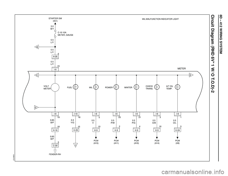
8D – 412 WIRING SYSTEM
Circuit Diagram (RHD 6V*1 W/O T.O.D)-2
�%�����3�8������
BCD
J
E
5 18 15105
2 25
4 21
163
5 1
19 156
VOLT
METERC-10 10A
METER, GAUGE
CHECK
TRANS.A/T OIL
TEMP.
18
C-39 H-16I-9
PCM
(A13)PCM
(A11)PCM
(A10)PCM
(A14)PCM
(A9)
0.5
V0.5
P/W0.5
P/G0.5
O/B0.5
O/L 0.85
B/PH-26
I-9 0.5
L/Y0.5
L/Y0.5
L/Y3.0
B/Y STARTER SW
(IG1)
0.3
Y/G
0.85
B/P
FENDER-RH
I-10
H-25I-9
H-9I-9
H-9I-9
H-9I-9
H-9I-9
H-24 FUEL MIL POWER WINTER
METER
MIL:MALFUNCTION INDICATOR LIGHT
Page 3007 of 3573
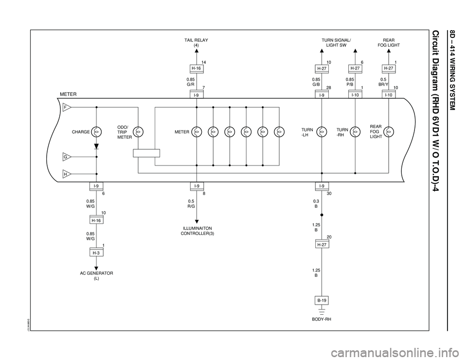
8D – 414 WIRING SYSTEM
Circuit Diagram (RHD 6VD1 W/O T.O.D)-4
�%�����3�8������
FGH
6
10
AC GENERATOR
(L)ILLUMINAITON
CONTROLLER(3)TAIL RELAY
(4)TURN SIGNAL/
LIGHT SWREAR
FOG LIGHT
BODY-RH 0.85
W/G
0.85
W/GI-9
H-161
H-38
0.5
R/G30
0.3
B 0.85
G/B 0.85
G/R0.85
P/B
1.25
B
1.25
B20
I-9H-27
B-191
6
2810
I-10 H-27
714
I-9 CHARGE METERTURN
-LHTURN
-RH0.5
BR/Y
101
I-10 H-27
REAR
FOG
LIGHT ODO/
TRIP
METER
METER
I-9 I-9 H-16
H-27
Page 3011 of 3573
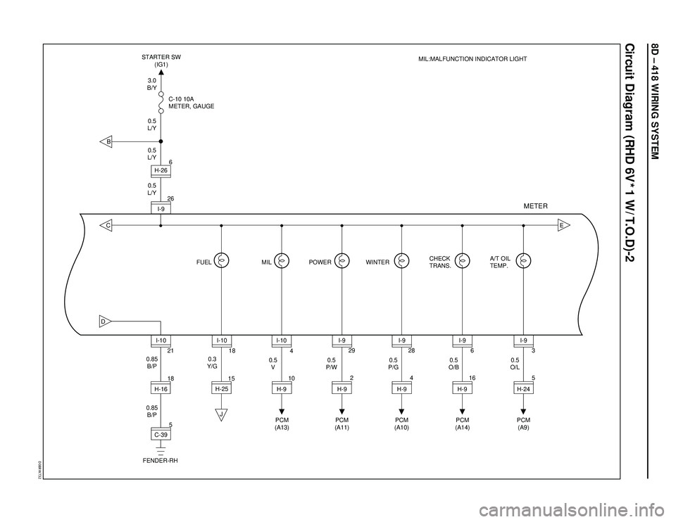
8D – 418 WIRING SYSTEM
Circuit Diagram (RHD 6V*1 W/T.O.D)-2
�%�����3�8������
BCD
J
E
5 18 15104
2 29
4 28
166
5 3
21 266 C-10 10A
METER, GAUGE
CHECK
TRANS.A/T OIL
TEMP.
18
C-39 H-16I-10
PCM
(A13)PCM
(A11)PCM
(A10)PCM
(A14)PCM
(A9) 0.5
V0.5
P/W0.5
P/G0.5
O/B0.5
O/L 0.85
B/PH-26
I-9 0.5
L/Y0.5
L/Y0.5
L/Y3.0
B/Y STARTER SW
(IG1)
0.3
Y/G
0.85
B/P
FENDER-RH
I-10
H-25I-10
H-9I-9
H-9I-9
H-9I-9
H-9I-9
H-24 FUEL MIL POWER WINTER
METER
MIL:MALFUNCTION INDICATOR LIGHT
Page 3013 of 3573
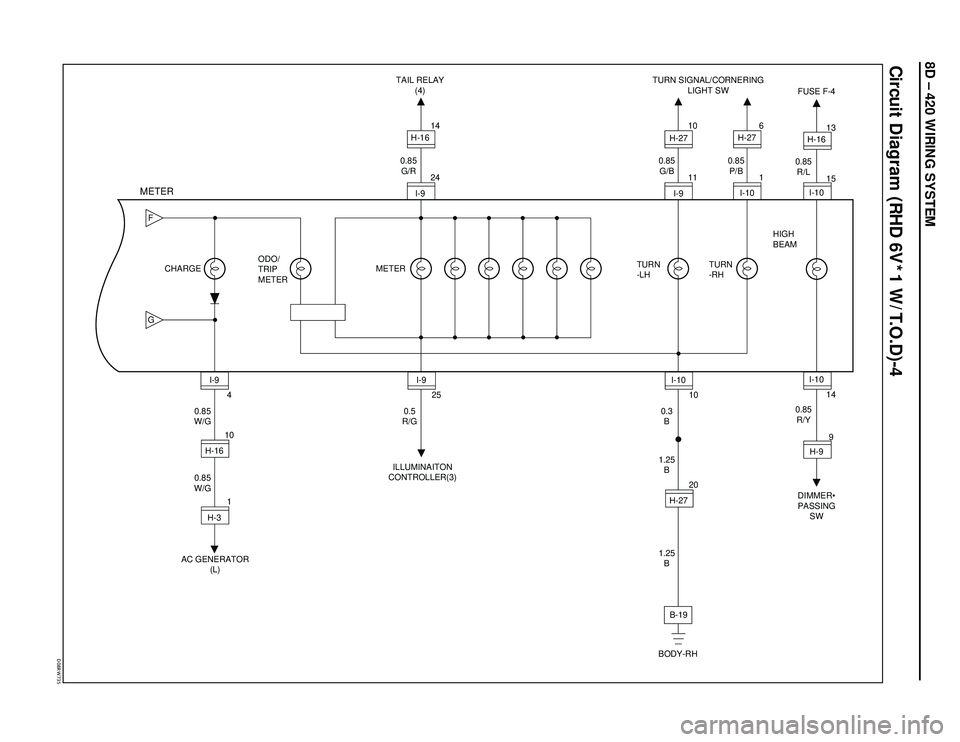
8D – 420 WIRING SYSTEM
Circuit Diagram (RHD 6V*1 W/T.O.D)-4
�%�����3�8������
FG
4
10
AC GENERATOR
(L)ILLUMINAITON
CONTROLLER(3)TAIL RELAY
(4)TURN SIGNAL/CORNERING
LIGHT SW
BODY-RH 0.85
W/G
0.85
W/GI-9
H-161
H-325
0.5
R/G10
0.3
B 0.85
G/B 0.85
G/R0.85
P/B
1.25
B
1.25
B20
I-10H-27
B-191
6
1110
I-10 H-27
2414
I-9 CHARGE METERTURN
-LHTURN
-RH ODO/
TRIP
METER
METER
I-9 I-9 H-16
H-27
DIMMER•
PASSING
SW FUSE F-4
0.85
R/Y 0.85
R/L
14 15 13
9 I-10 I-10 H-16
H-9 HIGH
BEAM
Page 3019 of 3573
8D – 426 WIRING SYSTEM
D08RW740
Circuit Diagram (RHD 4JG2)-4
JKM
6
10
CHARGE
RELAY
(1)ILLUMINAITON
CONTROLLER(3)TAIL RELAY
(4)TURN SIGNAL LIGHT SW
BODY-RH 0.85
W/G
0.85
W/GI-9
H-168
0.5
R/G30
0.3
B 0.85
G/B 0.85
G/R0.85
P/B
1.25
B
1.25
B20
L
I-9H-27
B-191
6
2810
I-10 H-27
714
I-9 CHARGE METERTURN
-LHTURN
-RH ODO/
TRIP
METER
METER
I-9 I-9 H-16
H-27
Page 3025 of 3573
8D – 432 WIRING SYSTEM
Circuit Diagram (LHD 6V*1 W/O T.O.D)-2
D08RW925
BCD
E
3 193 5
9 25
2 21
3 3
111
19 15 10
VOLT
METERC-10 10A
METER, GAUGE
CHECK
TRANS.A/T OIL
TEMP.
18
C-39 H-16I-9
PCM
(A13)PCM
(A11)PCM
(A10)PCM
(A14)PCM
(A9)
0.5
V0.5
GR/W0.5
P/G0.5
O/B0.5
O/L 0.85
B/PH-25
I-9 0.5
L/Y0.5
L/Y0.5
L/Y3.0
B/Y STARTER SW
(IG1)
0.3
Y/G
0.85
B/P
FENDER-RH
I-10
H-25I-9
H-9I-9
H-24I-9
H-24I-9
H-24I-9
H-24 FUEL MIL POWER WINTER
METER
MIL:MALFUNCTION INDICATOR LIGHT
J
Page 3027 of 3573
8D – 434 WIRING SYSTEM
Circuit Diagram (LHD 6V*1 W/O T.O.D)-4
D08RW927
FGH
6
5
AC GENERATOR
(L)ILLUMINAITON
CONTROLLER(3)TAIL RELAY
(4)TURN SIGNAL/CORNERING
LIGHT SW
BODY-RH 0.85
W/G
0.85
W/GI-9
H-161
H-38
0.5
R/G30
0.3
B 0.85
G/B 0.85
G/R0.85
P/B
2.0
B
2.0
B15
I-9H-48
B-21
19
2820
I-10 H-25
713
I-9 CHARGE METERTURN
-LHTURN
-RH ODO/
TRIP
METER
METER
I-9 I-9 H-16
H-25
Page 3033 of 3573
8D – 440 WIRING SYSTEM
Circuit Diagram (LHD 4JG2)-4
D08RW917
JKM
6
5
CHAGE
RELAY
(1)ILLUMINAITON
CONTROLLER(3)TAIL RELAY
(4)TURN SIGNAL/CORNERING
LIGHT SW
BODY-RH 0.85
W/G
0.85
W/GI-9
H-168
0.5
R/G30
0.3
B 0.85
G/B 0.85
G/R0.85
P/B
2.0
B
2.0
B15
L
I-9H-48
B-21
19
2820
I-10 H-25
76
I-9 CHARGE METERTURN
-LHTURN
-RH ODO/
TRIP
METER
METER
I-9 I-9 H-16
H-25

-4
JKM
6
10
CHARGE
RELAY
(1)ILLUMINAITON
CONTROLLER(3)TAIL RELAY
(4)TURN SIGNAL LIGHT SW
BODY-RH 0.85
W/G
0.85
W/GI-9
H-168
0.5
R/G30
0.3
B")
-2
D08RW925
BCD
E
3 193 5
9 25
2 21
3 3
111
19 15 10
VOLT
METERC-10 10A
METER, GAUGE
CHECK
TRANS.A/T OIL
TEMP.
18
C-39 H-16I-9
PCM
(A13)PCM")
-4
D08RW927
FGH
6
5
AC GENERATOR
(L)ILLUMINAITON
CONTROLLER(3)TAIL RELAY
(4)TURN SIGNAL/CORNERING
LIGHT SW
BODY-RH 0.85
W/G
0.85
W/GI-9
H-1")
-4
D08RW917
JKM
6
5
CHAGE
RELAY
(1)ILLUMINAITON
CONTROLLER(3)TAIL RELAY
(4)TURN SIGNAL/CORNERING
LIGHT SW
BODY-RH 0.85
W/G
0.85
W/GI-9
H-168
0.5
R/G3")