JAGUAR S TYPE 2005 1.G Technical Guide Update
Manufacturer: JAGUAR, Model Year: 2005, Model line: S TYPE, Model: JAGUAR S TYPE 2005 1.GPages: 133, PDF Size: 3.48 MB
Page 81 of 133
JAGUARS-TYPEElectrical/Electronic
76Air Conditioning Control Module (A/CCM)
The A/CCM is connected to the SCP
communication network. The A/CCM controls
automatic climate functions that maintain the
vehicle at a constant temperature setting.
Instrument Pack
The instrument pack is connected to the SCP
communication network. The instrument pack
displays information received on the SCP
including speedometer, odometer, fuel, and
message center warnings. The instrument pack
also controls the passive anti-theft system (PATS).
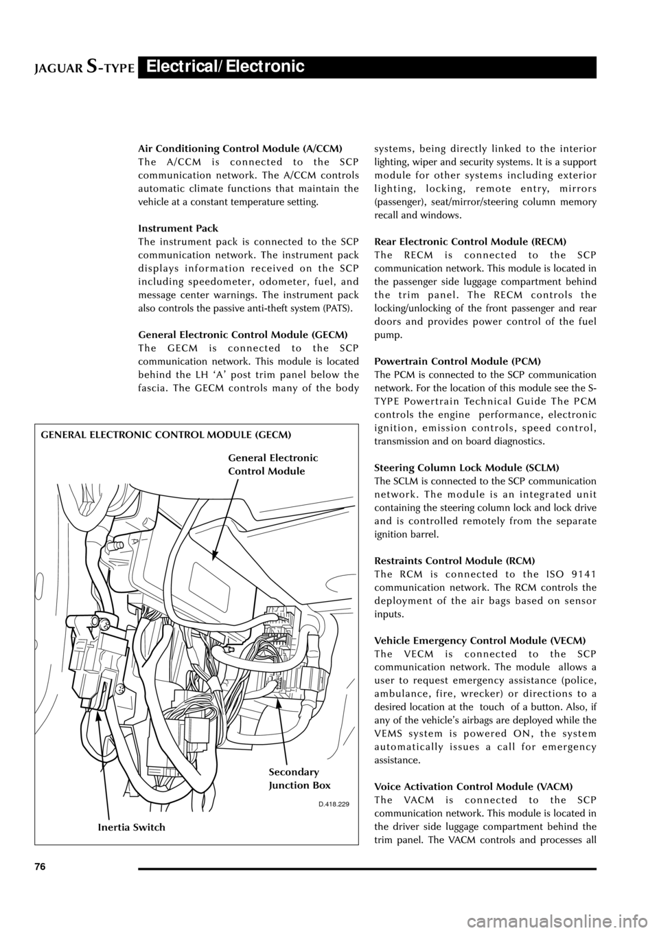
General Electronic Control Module (GECM)
The GECM is connected to the SCP
communication network. This module is located
behind the LH ÔAÕ post trim panel below the
fascia. The GECM controls many of the bodysystems, being directly linked to the interior
lighting, wiper and security systems. It is a support
module for other systems including exterior
lighting, locking, remote entry, mirrors
(passenger), seat/mirror/steering column memory
recall and windows.
Rear Electronic Control Module (RECM)
The RECM is connected to the SCP
communication network. This module is located in
the passenger side luggage compartment behind
the trim panel. The RECM controls the
locking/unlocking of the front passenger and rear
doors and provides power control of the fuel
pump.
Powertrain Control Module (PCM)
The PCM is connected to the SCP communication
network. For the location of this module see the S-
TYPE Powertrain Technical Guide The PCM
controls the engine performance, electronic
ignition, emission controls, speed control,
transmission and on board diagnostics.
Steering Column Lock Module (SCLM)
The SCLM is connected to the SCP communication
network. The module is an integrated unit
containing the steering column lock and lock drive
and is controlled remotely from the separate
ignition barrel.
Restraints Control Module (RCM)
The RCM is connected to the ISO 9141
communication network. The RCM controls the
deployment of the air bags based on sensor
inputs.
Vehicle Emergency Control Module (VECM)
The VECM is connected to the SCP
communication network. The module allows a
user to request emergency assistance (police,
ambulance, fire, wrecker) or directions to a
desired location at the touch of a button. Also, if
any of the vehicleÕs airbags are deployed while the
VEMS system is powered ON, the system
automatically issues a call for emergency
assistance.
Voice Activation Control Module (VACM)
The VACM is connected to the SCP
communication network. This module is located in
the driver side luggage compartment behind the
trim panel. The VACM controls and processes all
D.418.229
GENERAL ELECTRONIC CONTROL MODULE (GECM)
Inertia Switch
Secondary
Junction Box
General Electronic
Control Module
Page 82 of 133

JAGUARS-TYPEElectrical/Electronic
77 the voice commands given by the driver. It
delivers this information to the audio unit, GSM
or AMPS cellular phones and the A/CCM which
then carry out these commands.
Page 83 of 133
JAGUARS-TYPEElectrical/Electronic
78
Fuses and Relays
Fuses
Fuse failure is identified by an inoperative circuit.
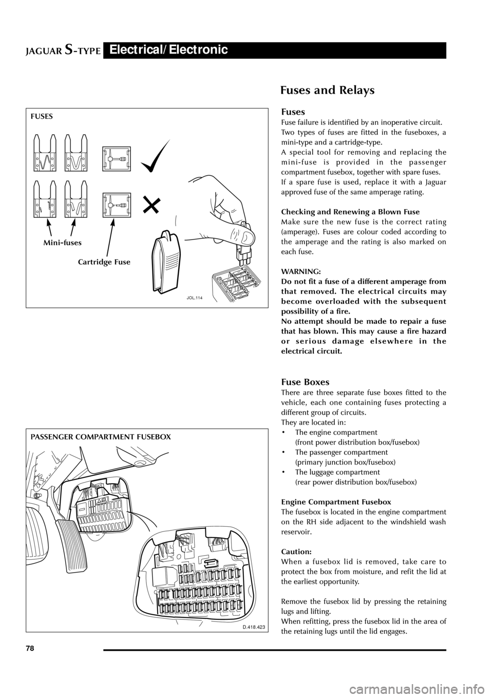
Two types of fuses are fitted in the fuseboxes, a
mini-type and a cartridge-type.
A special tool for removing and replacing the
mini-fuse is provided in the passenger
compartment fusebox, together with spare fuses.
If a spare fuse is used, replace it with a Jaguar
approved fuse of the same amperage rating.
Checking and Renewing a Blown Fuse
Make sure the new fuse is the correct rating
(amperage). Fuses are colour coded according to
the amperage and the rating is also marked on
each fuse.
WARNING:
Do not fit a fuse of a different amperage from
that removed. The electrical circuits may
become overloaded with the subsequent
possibility of a fire.
No attempt should be made to repair a fuse
that has blown. This may cause a fire hazard
or serious damage elsewhere in the
electrical circuit.
Fuse Boxes
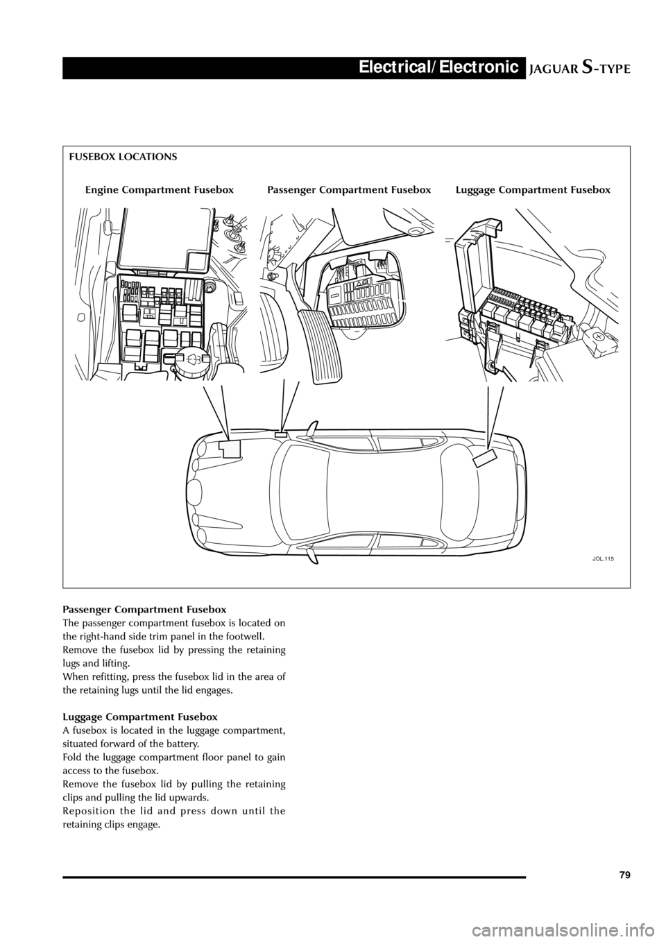
There are three separate fuse boxes fitted to the
vehicle, each one containing fuses protecting a
different group of circuits.
They are located in:
¥ The engine compartment
(front power distribution box/fusebox)
¥ The passenger compartment
(primary junction box/fusebox)
¥ The luggage compartment
(rear power distribution box/fusebox)
Engine Compartment Fusebox
The fusebox is located in the engine compartment
on the RH side adjacent to the windshield wash
reservoir.
Caution:
When a fusebox lid is removed, take care to
protect the box from moisture, and refit the lid at
the earliest opportunity.
Remove the fusebox lid by pressing the retaining
lugs and lifting.
When refitting, press the fusebox lid in the area of
the retaining lugs until the lid engages.
JOL.114
FUSES
Mini-fuses
Cartridge Fuse
D.418.423
1010
PASSENGER COMPARTMENT FUSEBOX
Page 84 of 133
JAGUARS-TYPEElectrical/Electronic
79 Passenger Compartment Fusebox
The passenger compartment fusebox is located on
the right-hand side trim panel in the footwell.
Remove the fusebox lid by pressing the retaining
lugs and lifting.
When refitting, press the fusebox lid in the area of
the retaining lugs until the lid engages.
Luggage Compartment Fusebox
A fusebox is located in the luggage compartment,
situated forward of the battery.
Fold the luggage compartment floor panel to gain
access to the fusebox.
Remove the fusebox lid by pulling the retaining
clips and pulling the lid upwards.
Reposition the lid and press down until the
retaining clips engage.
JOL.115
Engine Compartment FuseboxLuggage Compartment FuseboxPassenger Compartment Fusebox FUSEBOX LOCATIONS
Page 85 of 133
JAGUARS-TYPEElectrical/Electronic
80
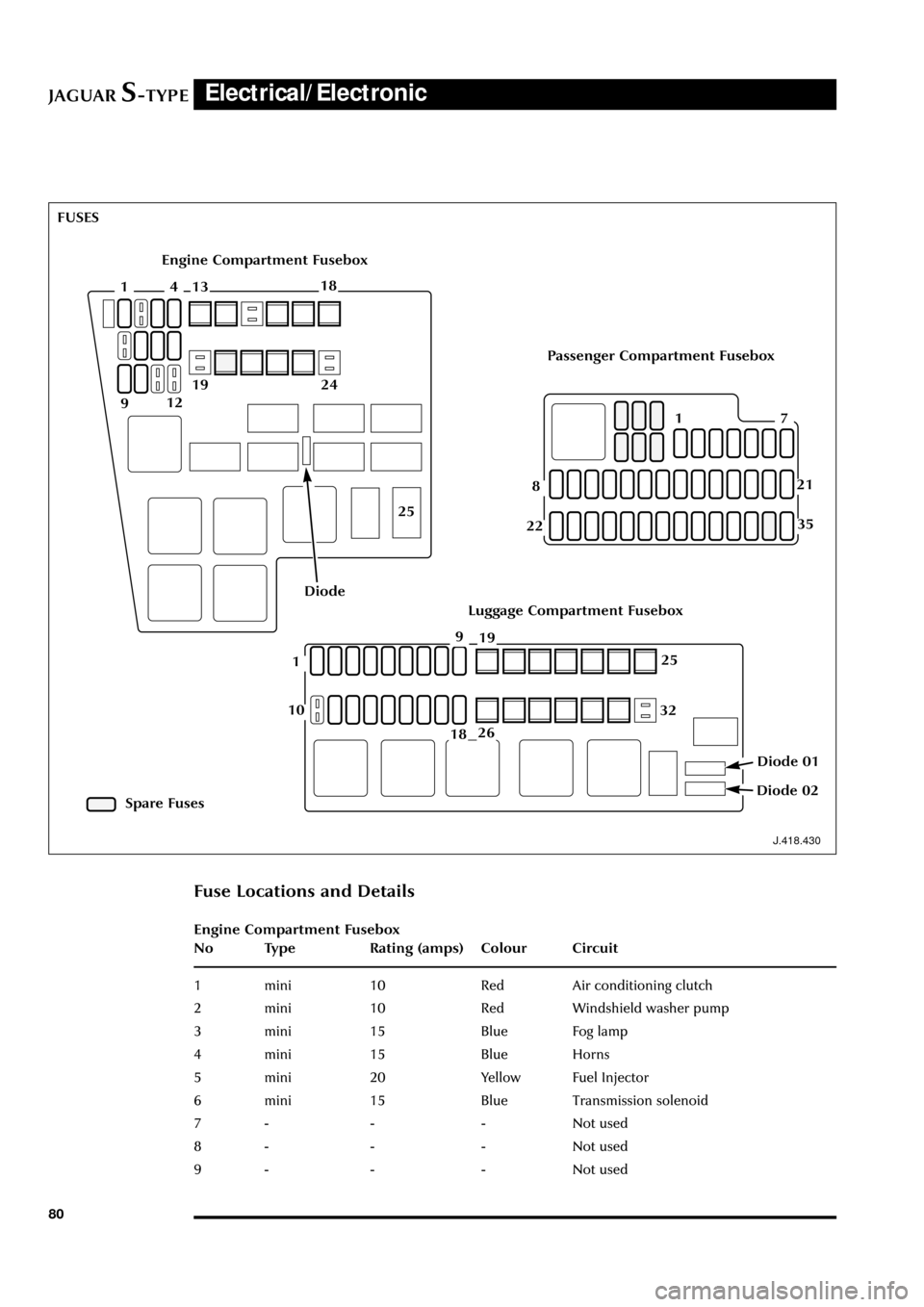
J.418.430
Fuse Locations and Details
Engine Compartment Fusebox
No Type Rating (amps) Colour Circuit
1 mini 10 Red Air conditioning clutch
2 mini 10 Red Windshield washer pump
3 mini 15 Blue Fog lamp
4 mini 15 Blue Horns
5 mini 20 Yellow Fuel Injector
6 mini 15 Blue Transmission solenoid
7 - - - Not used
8 - - - Not used
9 - - - Not used
Engine Compartment Fusebox
Luggage Compartment Fusebox
Passenger Compartment Fusebox
Spare Fuses FUSES
411318
912
2419
25
Diode
71
8
22
21
251
18
10
9
32
26
19
Diode 02
Diode 01
35
Page 86 of 133

JAGUARS-TYPEElectrical/Electronic
81 No Type Rating (amps) Colour Circuit
10 - - - Not used
11 mini 15 Blue HO2 sensor (catalyst)
12 mini 10 Red Coil on plug
13 cartridge 40 or 30 Green or Pink RH heated windshield or heated wiper
park (where fitted)
14 - - - Not used
15 cartridge 40 Green LH heated windshield
16 cartridge 30 Pink Blower motor
17 - - - Not used
18 cartridge 40 Green Powertrain control module (PCM)
19 - - - Not used
20 - - - Not used
21 cartridge 30 Pink Starter solenoid
22 cartridge 30 Pink ABS motor
23 cartridge 20 Blue Wiper motor
24 cartridge 30 Pink Head lamp washer pump
25 cartridge 80 - Cooling fan motor
Diode 1 PCM
Passenger Compartment Fusebox
No Type Rating (amps) Colour Circuit
1 mini 5 Brown Starter relay coil via Park/Neutral switch
2 mini 5 Brown Radio
3 mini 5 Brown ABS/DSC module
4 mini 5 Brown PCM relay coil, instrument pack, RECM,
fuel pump relay, transit relay
5 mini 5 Brown Autolamp sensor, heated seat module
switch & overdrive cancel switch RSM, BSI
6 mini 10 Red OBDII
7 mini 5 Brown DDCM, DSCM, PCM, Anti-theft LED,
security horn, power mirror
8 mini 5 Brown Right-front direction indicators, side
repeaters, side markers, park lights
9 mini 10 Red Right-front low beam headlamp
10 mini 5 Brown Left-front direction indicators side
repeaters, side markers, park lamps
11 mini 10 Red Left-front main beam lamp
12 mini 10 Red Headlamp levelling, ABS/DSC module
13 mini 5 Brown Instrument pack
14 mini 10 Red RCM, Dual Automatic Temperature
Control (DATC) module
Page 87 of 133

JAGUARS-TYPEElectrical/Electronic
82No Type Rating (amps) Colour Circuit
15 mini 5 Brown Adaptive damping module (ADRC)
16 mini 5 Brown Heated seat switch module,
electrochromic mirror, rain sensor
17 mini 5 Brown RCM, Generator warning lamp
18 mini 20 Yellow Radio, cellular phone, navigation unit
19 mini 15 Blue Steering column motors
20 mini 10 Red GECM, DATC, RECM, Instrument Pack,
brake shift interlock
21 mini 10 Red Power folding mirrors, electric sunblind
22 mini 10 Red DriverÕs door mirror, driverÕs door lock
motor
23 mini 10 Red Right-front high beam
24 mini 5 Brown Passive Anti-Theft System (PATS)
25 mini 10 Red Left-front low beam headlamp
26 - - - Not used
27 mini 10 Red Navigation display, radio, phone,
navigation module, Traffic Master
28 mini 5 Brown Battery-backed security sounder
29 mini 5 Brown Voice control, reversing aid, GECM,
Trailer tow ignition sense, VEMS
30 mini 5 Brown GECM
31 - - - Not used
32 mini 20 Yellow Accessory socket, cigar lighter
33 mini 10 Red GECM illumination power
34 - - - Not used
35 mini 5 Brown Stop lamp switch
Trunk Fusebox
No Type Rating (amps) Colour Circuit
1 mini 15 Blue Luggage compartment release solenoid
2 mini 10 Red Right rear direction indicators, back up,
fog lamps, side markers
3 mini 10 Red Left stop lamp
4 mini 10 Red Fuel door release solenoid
5 mini 10 Red Courtesy and map lamps
6 mini 10 Red Left rear direction indicators, back up,
fog lamps, side markers
7 mini 10 Red Right stop lamp
8 mini 10 Red Center high mounted stop lamp
9 mini 5 Brown Heated mirror
10 mini 5 Brown Traffic Master
11 mini 15 Blue Heated seats
Page 88 of 133

JAGUARS-TYPEElectrical/Electronic
83 No Type Rating (amps) Colour Circuit
12 mini 5 Brown RECM - logic, Transit relay
13 mini 15 Blue Adaptive damper ride control (ADRC)
14 mini 5 Brown Phone, CD, Vehicle emergency message
system (VEMS)
15 mini 5 Brown Alternator sense
16 mini 20 Yellow Sliding roof
17 mini 15 Blue Fuel pump
18 mini 20 Yellow Subwoofer amplifier
19 cartridge 20 Blue RECM, left rear window
20 cartridge 30 Pink Driver door module - Driver window
21 cartridge 30 Pink Driver lumbar
22 cartridge 20 Blue Ignition
23 cartridge 30 Pink Switched system power 4
24 cartridge 30 Pink Switched system power 3
25 cartridge 40 Green Primary junction box
26 cartridge 30 Pink GECM Passenger window
(30amp early cars)
27 cartridge 30 Pink RECM, right rear window
28 cartridge 30 Pink Passenger lumbar
29 cartridge 30 Pink Rear defroster
30 cartridge 20 Blue Switched system power 1
31 cartridge 30 Pink Switched system power 2
32 - - - Unused
Diode 01 Unused
Diode 02 1 Fuel pump motor
Page 89 of 133
JAGUARS-TYPEElectrical/Electronic
84
J.418.431
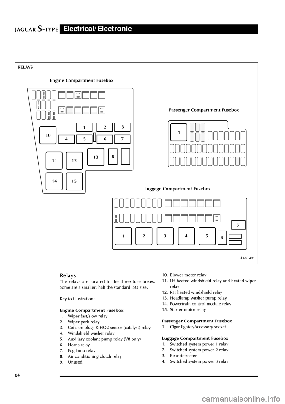
Engine Compartment Fusebox
Luggage Compartment Fusebox
Passenger Compartment Fusebox
Relays
The relays are located in the three fuse boxes.
Some are a smaller: half the standard ISO size.
Key to illustration:
Engine Compartment Fusebox
1. Wiper fast/slow relay
2. Wiper park relay
3. Coils on plugs & HO2 sensor (catalyst) relay
4. Windshield washer relay
5. Auxiliary coolant pump relay (V8 only)
6. Horns relay
7. Fog lamp relay
8. Air conditioning clutch relay
9. Unused10. Blower motor relay
11. LH heated windshield relay and heated wiper
relay
12. RH heated windshield relay
13. Headlamp washer pump relay
14. Powertrain control module relay
15. Starter motor relay
Passenger Compartment Fusebox
1. Cigar lighter/Accessory socket
Luggage Compartment Fusebox
1. Switched system power 1 relay
2. Switched system power 2 relay
3. Rear defroster
4. Switched system power 3 relay RELAYS
213
7
13
510
1211
1514
64
8
213
7
564
1
Page 90 of 133
JAGUARS-TYPEElectrical/Electronic
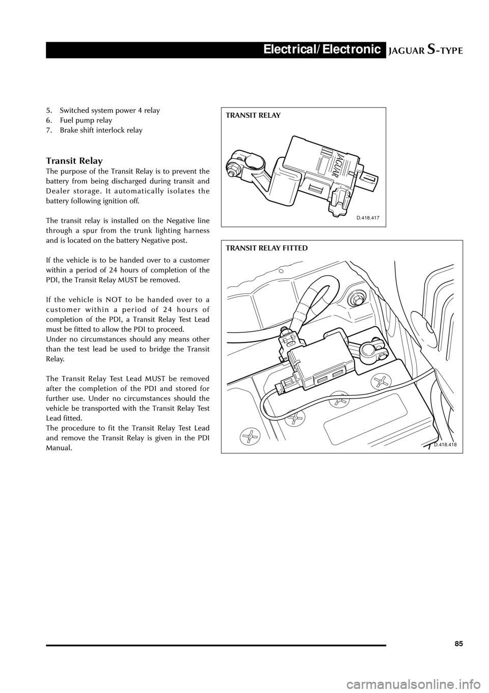
85 5. Switched system power 4 relay
6. Fuel pump relay
7. Brake shift interlock relay
Transit Relay
The purpose of the Transit Relay is to prevent the
battery from being discharged during transit and
Dealer storage. It automatically isolates the
battery following ignition off.
The transit relay is installed on the Negative line
through a spur from the trunk lighting harness
and is located on the battery Negative post.
If the vehicle is to be handed over to a customer
within a period of 24 hours of completion of the
PDI, the Transit Relay MUST be removed.
If the vehicle is NOT to be handed over to a
customer within a period of 24 hours of
completion of the PDI, a Transit Relay Test Lead
must be fitted to allow the PDI to proceed.
Under no circumstances should any means other
than the test lead be used to bridge the Transit
Relay.
The Transit Relay Test Lead MUST be removed
after the completion of the PDI and stored for
further use. Under no circumstances should the
vehicle be transported with the Transit Relay Test
Lead fitted.
The procedure to fit the Transit Relay Test Lead
and remove the Transit Relay is given in the PDI
Manual.
D.418.417
D.418.418
TRANSIT RELAY
TRANSIT RELAY FITTED