JAGUAR S TYPE 2005 1.G Technical Guide Update
Manufacturer: JAGUAR, Model Year: 2005, Model line: S TYPE, Model: JAGUAR S TYPE 2005 1.GPages: 133, PDF Size: 3.48 MB
Page 41 of 133
JAGUARS-TYPE
D.418.233
Occupant Protection
36
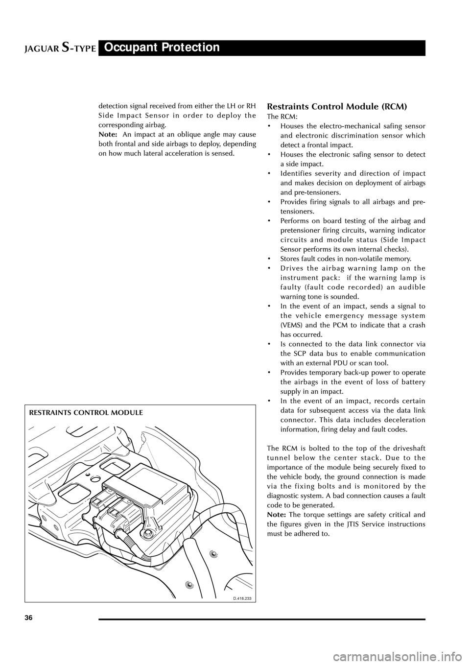
Restraints Control Module (RCM)
The RCM:
¥ Houses the electro-mechanical safing sensor
and electronic discrimination sensor which
detect a frontal impact.
¥ Houses the electronic safing sensor to detect
a side impact.
¥ Identifies severity and direction of impact
and makes decision on deployment of airbags
and pre-tensioners.
¥ Provides firing signals to all airbags and pre-
tensioners.
¥ Performs on board testing of the airbag and
pretensioner firing circuits, warning indicator
circuits and module status (Side Impact
Sensor performs its own internal checks).
¥ Stores fault codes in non-volatile memory.
¥ Drives the airbag warning lamp on the
instrument pack: if the warning lamp is
faulty (fault code recorded) an audible
warning tone is sounded.
¥ In the event of an impact, sends a signal to
the vehicle emergency message system
(VEMS) and the PCM to indicate that a crash
has occurred.
¥ Is connected to the data link connector via
the SCP data bus to enable communication
with an external PDU or scan tool.
¥ Provides temporary back-up power to operate
the airbags in the event of loss of battery
supply in an impact.
¥ In the event of an impact, records certain
data for subsequent access via the data link
connector. This data includes deceleration
information, firing delay and fault codes.
The RCM is bolted to the top of the driveshaft
tunnel below the center stack. Due to the
importance of the module being securely fixed to
the vehicle body, the ground connection is made
via the fixing bolts and is monitored by the
diagnostic system. A bad connection causes a fault
code to be generated.
Note:The torque settings are safety critical and
the figures given in the JTIS Service instructions
must be adhered to. RESTRAINTS CONTROL MODULE
D.418.233
detection signal received from either the LH or RH
Side Impact Sensor in order to deploy the
corresponding airbag.
Note:An impact at an oblique angle may cause
both frontal and side airbags to deploy, depending
on how much lateral acceleration is sensed.
Page 42 of 133
JAGUARS-TYPEOccupant Protection
37
D.418.445
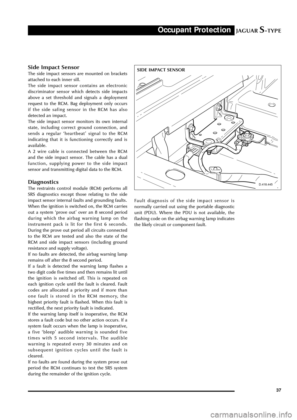
SIDE IMPACT SENSORSide Impact Sensor
The side impact sensors are mounted on brackets
attached to each inner sill.
The side impact sensor contains an electronic
discriminator sensor which detects side impacts
above a set threshold and signals a deployment
request to the RCM. Bag deployment only occurs
if the side safing sensor in the RCM has also
detected an impact.
The side impact sensor monitors its own internal
state, including correct ground connection, and
sends a regular ÔheartbeatÕ signal to the RCM
indicating that it is functioning correctly and is
available.
A 2 wire cable is connected between the RCM
and the side impact sensor. The cable has a dual
function, supplying power to the side impact
sensor and transmitting digital data to the RCM.
Diagnostics
The restraints control module (RCM) performs all
SRS diagnostics except those relating to the side
impact sensor internal faults and grounding faults.
When the ignition is switched on, the RCM carries
out a system Ôprove outÕ over an 8 second period
during which the airbag warning lamp on the
instrument pack is lit for the first 6 seconds.
During the prove out period all circuits connected
to the RCM are tested and also the state of the
RCM and side impact sensors (including ground
resistance and supply voltage).
If no faults are detected, the airbag warning lamp
remains off after the 8 second period.
If a fault is detected the warning lamp flashes a
two digit code five times and then remains lit until
the ignition is switched off. This is repeated on
each ignition cycle until the fault is cleared. Fault
codes are allocated a priority and if more than
one fault is stored in the RCM memory, the
highest priority fault is flashed. When this fault is
rectified, the next priority fault is indicated.
If the warning lamp itself is inoperative, the RCM
stores a fault code but no other action occurs. If a
system fault occurs when the lamp is inoperative,
a five ÔbleepÕ audible warning is sounded five
times with 5 second intervals. The audible
warning is repeated every 30 minutes and on
subsequent ignition cycles until the fault is
cleared.
If no faults are found during the system prove out
period the RCM continues to test the SRS system
during the remainder of the ignition cycle.Fault diagnosis of the side impact sensor is
normally carried out using the portable diagnostic
unit (PDU). Where the PDU is not available, the
flashing code on the airbag warning lamp indicates
the likely circuit or component fault.
Page 43 of 133
JAGUARS-TYPEFuel System
38
Introduction
The fuel tank components, operation and layout
are new to Jaguar and have no commonality with
previous systems. The major features of the fuel
delivery system are the use of a saddle type tank
and a returnless fuel system. The evaporative loss
management system is similar in operation to that
fitted to the XJ and XK Series vehicles and on-
board refuelling vapour recovery (ORVR) is a
standard feature. For NAS markets only, leak test
diagnostics are performed.
Returnless Fuel System
The returnless fuel system delivers the correct
amount of fuel to the engine under all conditions
and at a constant pressure differential with
respect to manifold pressure. This is without the
need for a return line to the tank or a fuel rail
pressure regulator. The use of a return line and
the pressure drop across a regulator contribute to
vapour formation which can affect fuelling
calibration and requires a complex vapour
management system to meet legislative
requirements. Elimination of these components,
D.310.047
together with closed loop control of the variable
speed fuel pump, causes a reduction in the vapour
generated, lower fuel temperatures and better fuel
pressure control. Additional advantages include a
reduced load on the electrical system and
improved fuel economy.
Fuel Tank
The fuel tank is of the ÔsaddleÕ type shape with LH
and RH fuel compartments and is constructed of
high density polyethylene (HDPE), a plastic blow
moulded material. The tank is located below the
rear passenger seat with the drive shaft and
exhaust running through the arch of the tank. The
underside of the tank is protected by a fitted heat
shield and the tank assembly is retained by two
metal straps which are fixed to the underbody at
the front by removeable hinge pins and at the rear
by bolts.
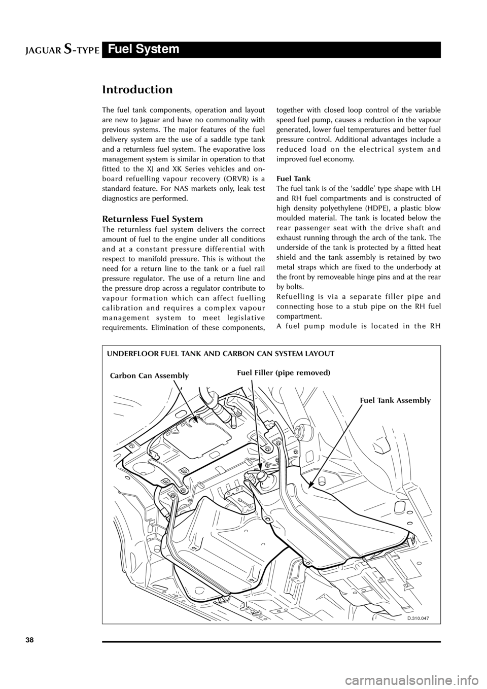
Refuelling is via a separate filler pipe and
connecting hose to a stub pipe on the RH fuel
compartment.
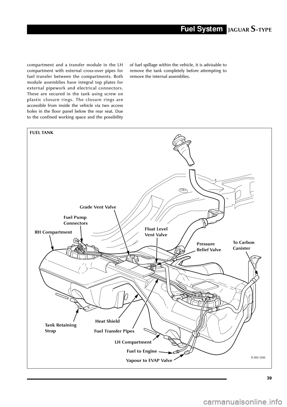
A fuel pump module is located in the RH
UNDERFLOOR FUEL TANK AND CARBON CAN SYSTEM LAYOUT
Carbon Can AssemblyFuel Filler (pipe removed)
Fuel Tank Assembly
Page 44 of 133
JAGUARS-TYPEFuel System
39
D.303.1242
compartment and a transfer module in the LH
compartment with external cross-over pipes for
fuel transfer between the compartments. Both
module assemblies have integral top plates for
external pipework and electrical connectors.
These are secured in the tank using screw on
plastic closure rings. The closure rings are
accessible from inside the vehicle via two access
holes in the floor panel below the rear seat. Due
to the confined working space and the possibilityof fuel spillage within the vehicle, it is advisable to
remove the tank completely before attempting to
remove the internal assemblies.
FUEL TANK
Grade Vent Valve
Fuel Pump
Connectors
Pressure
Relief Valve
Float Level
Vent Valve
Heat Shield
To Carbon
Canister
Vapour to EVAP Valve
Fuel to Engine
Fuel Transfer Pipes
Tank Retaining
Strap
LH Compartment
RH Compartment
Page 45 of 133
JAGUARS-TYPEFuel System
40
J.310.046
Fuel Filter
Fuel Rail
Fuel Injectors
Fuel Injectors
Fuel Level
Senders
Jet PumpJet PumpFuel Pump
Fuel Reservoir
Parallel Pressure
Relief Valve
Pump and Sender
Electrical Connector
RH Compartment
LH Compartment
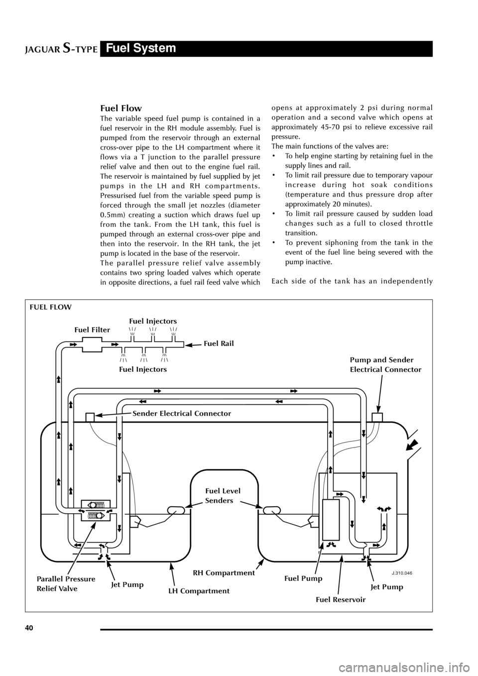
Fuel Flow
The variable speed fuel pump is contained in a
fuel reservoir in the RH module assembly. Fuel is
pumped from the reservoir through an external
cross-over pipe to the LH compartment where it
flows via a T junction to the parallel pressure
relief valve and then out to the engine fuel rail.
The reservoir is maintained by fuel supplied by jet
pumps in the LH and RH compartments.
Pressurised fuel from the variable speed pump is
forced through the small jet nozzles (diameter
0.5mm) creating a suction which draws fuel up
from the tank. From the LH tank, this fuel is
pumped through an external cross-over pipe and
then into the reservoir. In the RH tank, the jet
pump is located in the base of the reservoir.
The parallel pressure relief valve assembly
contains two spring loaded valves which operate
in opposite directions, a fuel rail feed valve whichopens at approximately 2 psi during normal
operation and a second valve which opens at
approximately 45-70 psi to relieve excessive rail
pressure.
The main functions of the valves are:
¥ To help engine starting by retaining fuel in the
supply lines and rail.
¥ To limit rail pressure due to temporary vapour
increase during hot soak conditions
(temperature and thus pressure drop after
approximately 20 minutes).
¥ To limit rail pressure caused by sudden load
changes such as a full to closed throttle
transition.
¥ To prevent siphoning from the tank in the
event of the fuel line being severed with the
pump inactive.
Each side of the tank has an independently
FUEL FLOW
Sender Electrical Connector
Page 46 of 133
JAGUARS-TYPEFuel System
41
JOL.062
INERTIA SWITCH operating fuel level sender assembly mounted on
the respective module assembly.
Control and Operation
The speed of the fuel pump is varied under closed
loop control so as to deliver the required fuel rail
injection pressure in accordance with factors such
as driver demand, manifold pressure and
temperature changes. The control loop sensors,
providing feedback information to the powertrain
control module (PCM), are the engine fuel
temperature (EFT) sensor and the injection
pressure (IP) sensor which are both mounted
directly on the engine fuel rail (see
S-TYPE Powertrain Technical Guide). The IP sensor
also has a vacuum feed from the intake manifold
so as to measure the pressure differential.
The required fuel flow is determined by the PCM
and sent to the rear electronic control module
(RECM) which is the power driver for the fuel
pump. The PCM demand to the RECM is a pulse
width modulated (PWM) signal over a single line
at a frequency of approximately 256 Hz and a
duty cycle of 0-50%. The RECM effecively
amplifies this signal by increasing the frequency
by 64 and doubling the duty cycle, thus providing
the necessary high current drive for the fuel
pump. The fuel pump relay, located in the rear
power distribution box, is energised by the PCM
relay and provides a dedicated fused supply to the
RECM for the pump drive.
When the ignition switch is turned from OFF to
RUN or START, the PCM primes the system by
running the pump for 1 second at full speed. The
pump is switched off 1 second after the engine is
stopped. During hot starts, fuel pressure is
increased to prevent vapour lock.
Fuel pump drive status is monitored by the RECM
and communicated to the PCM via the SCP
network.
Outputs from the fuel senders are connected by
independent wires to the RECM which sends the
data to the instrument pack and the PCM.
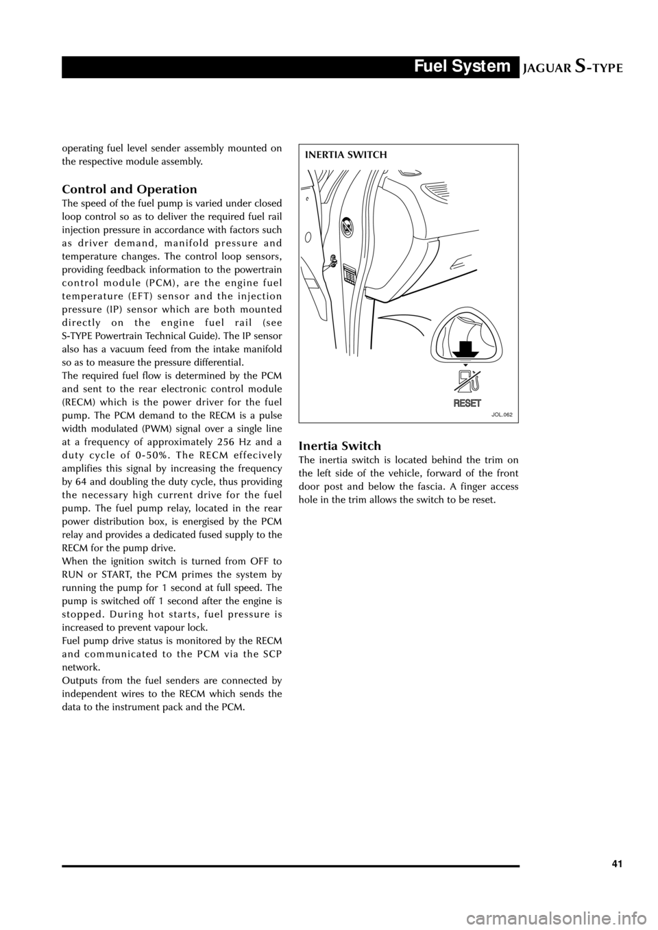
Inertia Switch
The inertia switch is located behind the trim on
the left side of the vehicle, forward of the front
door post and below the fascia. A finger access
hole in the trim allows the switch to be reset.
Page 47 of 133
JAGUARS-TYPEFuel System
42
Evaporative Emissions System
The function and operation of the on-board
refueling vapor recovery (ORVR) evaporative
emissions system are similar to the system fitted
to the XJ and XK Series vehicles in NAS markets
but use different components. For the S-TYPE the
system is fitted as standard for all markets.
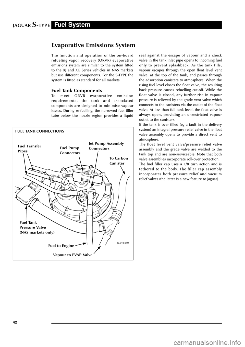
Fuel Tank Components
To meet ORVR evaporative emission
requirements, the tank and associated
components are designed to minimise vapour
losses. During re-fuelling, the narrowed fuel filler
tube below the nozzle region provides a liquidseal against the escape of vapour and a check
valve in the tank inlet pipe opens to incoming fuel
only to prevent splashback. As the tank fills,
vapour escapes through the open float level vent
valve, at the top of the tank, and passes through
the adsorption canisters to atmosphere. When the
rising fuel level closes the float valve, the resulting
back pressure causes refuelling cut-off. While the
float valve is closed, any further rise in vapour
pressure is relieved by the grade vent valve which
connects to the canisters via the outlet of the float
valve. At less than full tank level, the float valve is
always open, providing an unrestricted vapour
outlet to the canisters.
If the tank is over filled (eg a fault in the delivery
system) an integral pressure relief valve in the float
valve assembly opens to provide a direct vent to
atmosphere.
The float level vent valve/pressure relief valve
assembly and the grade valve are welded to the
tank top and are non-serviceable. Note that both
valve assemblies incorporate roll-over protection.
The fuel filler cap uses a 1/8 turn action and is
tethered to the body. The filler cap assembly
incorporates both pressure relief and vacuum
relief valves (the latter is a new feature to Jaguar).
D.310.049
FUEL TANK CONNECTIONS
Fuel Tank
Pressure Valve
(NAS markets only)
Jet Pump Assembly
Connectors
Fuel Pump
Connectors
To Carbon
Canister
Vapour to EVAP Valve
Fuel to Engine
Fuel Transfer
Pipes
Page 48 of 133
JAGUARS-TYPEFuel System
43
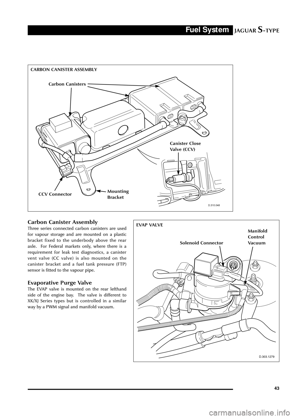
Carbon Canister Assembly
Three series connected carbon canisters are used
for vapour storage and are mounted on a plastic
bracket fixed to the underbody above the rear
axle. For Federal markets only, where there is a
requirement for leak test diagnostics, a canister
vent valve (CC valve) is also mounted on the
canister bracket and a fuel tank pressure (FTP)
sensor is fitted to the vapour pipe.
Evaporative Purge Valve
The EVAP valve is mounted on the rear lefthand
side of the engine bay. The valve is different to
XK/XJ Series types but is controlled in a similar
way by a PWM signal and manifold vacuum.
D.310.048
D.303.1279
EVAP VALVE CARBON CANISTER ASSEMBLY
Carbon Canisters
CCV Connector
Canister Close
Valve (CCV)
Mounting
Bracket
Solenoid Connector
Manifold
Control
Vacuum
Page 49 of 133
JAGUARS-TYPEExhaust System
44
Introduction
D.309.080
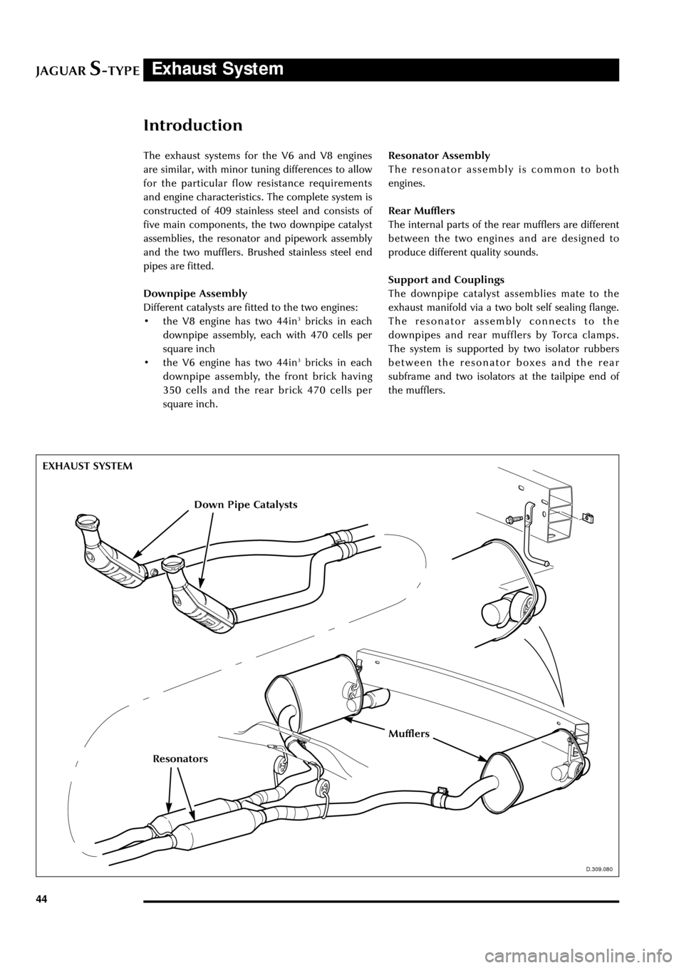
The exhaust systems for the V6 and V8 engines
are similar, with minor tuning differences to allow
for the particular flow resistance requirements
and engine characteristics. The complete system is
constructed of 409 stainless steel and consists of
five main components, the two downpipe catalyst
assemblies, the resonator and pipework assembly
and the two mufflers. Brushed stainless steel end
pipes are fitted.
Downpipe Assembly
Different catalysts are fitted to the two engines:
¥ the V8 engine has two 44in
3bricks in each
downpipe assembly, each with 470 cells per
square inch
¥ the V6 engine has two 44in
3bricks in each
downpipe assembly, the front brick having
350 cells and the rear brick 470 cells per
square inch.Resonator Assembly
The resonator assembly is common to both
engines.
Rear Mufflers
The internal parts of the rear mufflers are different
between the two engines and are designed to
produce different quality sounds.
Support and Couplings
The downpipe catalyst assemblies mate to the
exhaust manifold via a two bolt self sealing flange.
The resonator assembly connects to the
downpipes and rear mufflers by Torca clamps.
The system is supported by two isolator rubbers
between the resonator boxes and the rear
subframe and two isolators at the tailpipe end of
the mufflers.
EXHAUST SYSTEM
D.309.080
Down Pipe Catalysts
Resonators
Mufflers
Page 50 of 133
JAGUARS-TYPETransmission
45
Introduction
The automatic and manual transmission units are
described in the ÔS-TYPE Sports Sedan Powertrain
IntroductionÕ Technical Guide.
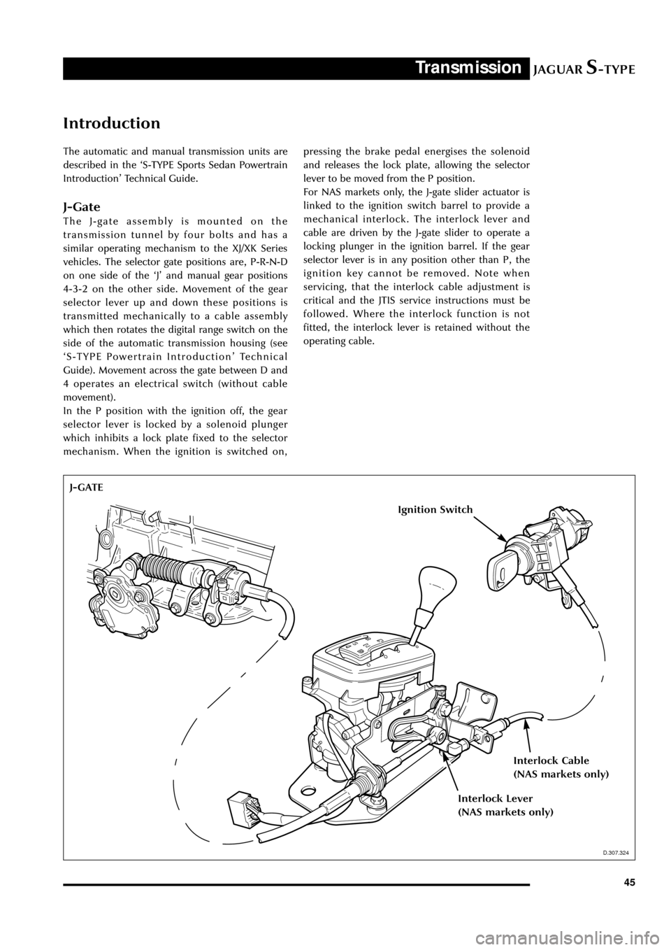
J-Gate
The J-gate assembly is mounted on the
transmission tunnel by four bolts and has a
similar operating mechanism to the XJ/XK Series
vehicles. The selector gate positions are, P-R-N-D
on one side of the ÔJÕ and manual gear positions
4-3-2 on the other side. Movement of the gear
selector lever up and down these positions is
transmitted mechanically to a cable assembly
which then rotates the digital range switch on the
side of the automatic transmission housing (see
ÔS-TYPE Powertrain IntroductionÕ Technical
Guide). Movement across the gate between D and
4 operates an electrical switch (without cable
movement).
In the P position with the ignition off, the gear
selector lever is locked by a solenoid plunger
which inhibits a lock plate fixed to the selector
mechanism. When the ignition is switched on,pressing the brake pedal energises the solenoid
and releases the lock plate, allowing the selector
lever to be moved from the P position.
For NAS markets only, the J-gate slider actuator is
linked to the ignition switch barrel to provide a
mechanical interlock. The interlock lever and
cable are driven by the J-gate slider to operate a
locking plunger in the ignition barrel. If the gear
selector lever is in any position other than P, the
ignition key cannot be removed. Note when
servicing, that the interlock cable adjustment is
critical and the JTIS service instructions must be
followed. Where the interlock function is not
fitted, the interlock lever is retained without the
operating cable.
D.307.324
J-GATE
Ignition Switch
Interlock Cable
(NAS markets only)
Interlock Lever
(NAS markets only)
D.307.324