Front crossmember JAGUAR X308 1998 2.G Workshop Manual
[x] Cancel search | Manufacturer: JAGUAR, Model Year: 1998, Model line: X308, Model: JAGUAR X308 1998 2.GPages: 2490, PDF Size: 69.81 MB
Page 34 of 2490

501‐20B : Supp l
emental
Restraint System
Specification
Description and Operation
Air Bag Supplemental Restraint System (SRS)
Removal and Installation
Air Bag Control Module (76.73.41)
Driver Air Bag Module (76.73.39)
Passenger Air Bag Module (76.73.37)
Side Air Bag Module (76.73.47)
Side Impact Sensor (76.73.53)
501‐25: Body Repairs ‐ Genera
l Information
Description and Operation
Body Repairs
502: Frame and Mounting
502‐00: Uni ‐Body, Subframe and Mounting System
Removal and Installation
Front Axle Crossmember
Front Axle Crossmember Front Bushing (60.35.24)
Front Axle Crossmember Front Bushing Heat Shield (60.35.37)
Front Axle Crossmember Rear Bushing (
60.35.26)
Rear Axle Crossmember (64.25.16)
Rear Axle Crossmember Bushing (64.25.02)
Page 49 of 2490
Identification
Codes -
Identification Codes
Descr
iption and Operation
En
gine Number
The en
gine number (10 digits) is stamped on a raised pad on th
e front of the engine block near the thermostat housing. The
piston grade reference (8 digits) is also shown.
Automatic Transmission
Number
The
serial number of the transmission unit is displayed on
a metal or bar code label attached to the LH side of the
transmission casing.
Veh
icle Identification
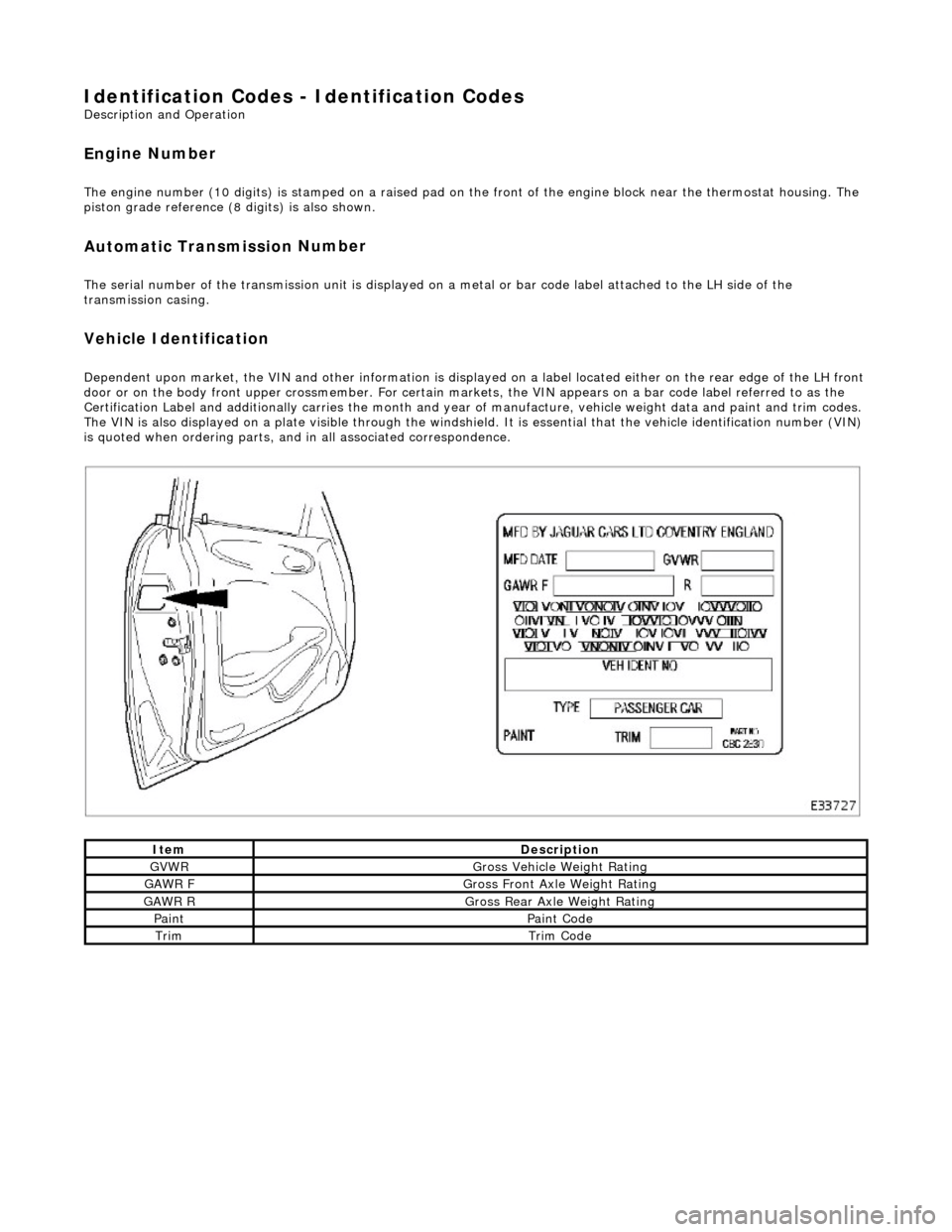
Dependent
upon market, the VIN and other info
rmation is displayed on a label located ei ther on the rear edge of the LH front
door or on the body front upper crossmember. For certain mark ets, the VIN appears on a bar code label referred to as the
Certification Label and additionally carries the month and year of manufacture, vehicle weight data and paint and trim codes.
The VIN is also displayed on a plate visible through the windshie ld. It is essential that the vehicle identification number (VIN)
is quoted when ordering parts, and in all associated correspondence.
ItemDe
scription
GVW
R
G
ross Vehicle Weight Rating
GAW
R F
Gros
s Front Axle Weight Rating
GAW
R R
Gros
s Rear Axle Weight Rating
Pai
nt
Pai
nt Code
TrimTrim
Code
Page 552 of 2490
Engine - Connecting Rod Bearings
In-vehic
le Repair
Remov
a
l
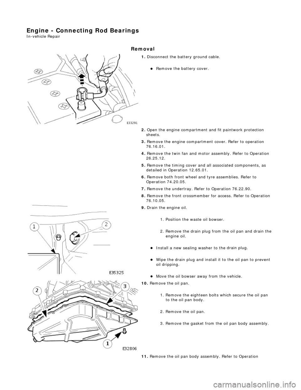
1.
Disc
onnect the batt
ery ground cable.
Re
move the battery cover.
2. Open the engine compartment and fit paintwork protection
sheets.
3. Remove the engine compartmen t cover. Refer to operation
76.16.01.
4. Remove the twin fan and motor assembly. Refer to Operation
26.25.12.
5. Remove the timing cover and al l associated components, as
detailed in Operation 12.65.01.
6. Remove both front wheel and tyre assemblies. Refer to
Operation 74.20.05.
7. Remove the undertray. Re fer to Operation 76.22.90.
8. Remove the front crossmember fo r access. Refer to Operation
76.10.05.
9. Drai
n the engine oil.
1. Position the waste oil bowser.
2. Remove the drain plug from the oil pan and drain the engine oil.
Install a new sealing wash er to the
drain plug.
Wipe the drain plug an
d
install
it to the oil pan to prevent
oil dripping.
Move the oil bowser away f
rom the vehicle.
10 . Re
move the oil pan.
1. Remove the eighteen bolt s which secure the oil pan
to the oil pan body.
2. Remove the oil pan.
3. Remove the gasket from the oil pan body assembly.
11. Remove the oil pan body a ssembly. Refer to Operation
Page 909 of 2490

1. Remove the nut which secures the selector lever to
the transmission cross shaft.
2. Remove the selector cable abutment bolts.
3. Disconnect the selector arm from the cross shaft.
67. Loosen the bolt which secures the engine rear mounting
rubber to the transmission.
68. Position a transmission jack e.g. Epco V100 and raise the
support bed of the jack to take the weight of the transmission.
Fit and adjust the chains to secure the transmission to the jack.
69. Remove the engine rear mounting assembly.
Remove the mounting centre bolt.
Remove the four bolts which secure the crossmember to
the body.
Remove the crossmember and mounting assembly.
70. Release the engine and tran smission assembly from the
engine compartment.
Take the weight of the engine / transmission with the
hoist and move it towards th e front of the vehicle.
Lower the transmission jack slightly to release the
securing chains. Remove the ja ck from below the vehicle.
Page 912 of 2490

Align th
e engine front mountings and fit the securing nuts.
Tighte
n to the stated torque value.
3. Operate the crane controls and the ramp simultaneously (with
assistance) to raise the vehicle to a convenient working height.
4. Po
sition the transmission jack and raise it to take the weight of
the transmission. Fit and adjust the chains to secure the
transmission to the jack.
5. Fit th
e engine rear mounting bracket.
Fi
t the four bolts which secu
re the crossmember to the
body.
Fi t t
he bolt which secures the
engine rear mounting rubber
to the transmission.
6. Tigh ten th
e rear mounting bolts
to the stated torque figure.
7. Release and remove the transmission jack.
8. Operate the crane controls and the ramp simultaneously (with
assistance) to lower the vehicle to a convenient working height.
9. Lower th e cran
e and remove th
e chain assembly and lifting
eyes.
Page 2024 of 2490
located behind the trunk lid badge.
Occupant Restraints
Inertia reel seat belts with electronically controlled pre-tensioners are installed at the front seats. Supplementary occupant
restraint is provided for driver and front seat passenger by front airbags, and side air bags installed in the outer wing of
each front seat. Standard inertia reel type belts are fitted to all three rear seat positions. The front seat belts are provide d
with height adjuster units which are attached one to each of the 'B' posts. Where emergency locking retractor/automatic
locking retractor seat belts are provided, the belts have two operating modes.The inertia reel mode with emergency locking
retractor is for adult passenge r use only and operates to allow the occupant some freedom of tors o movement under normal
travel conditions.. The static reel mode which prevents belt payout and must be used when a ch ild seat is installed, is
activated by fully extending the belt to engage the ratchet me chanism,.then releasing the belt. Operation of the ratchet will
then be felt and the belt w ill become locked in that position. To revert to in ertia reel (adult passenger) mode, pay the belt
back into the reel to th e fully retracted position.
Body Structure
The XJ8 sedan body is produced in monocoque standard and lo ng wheelbase form. 70% of the body panels are zinc coated
to achieve optimum corrosion protection and a further 8% are constructed in high st rength steels to provide high torsional
strength and passenger impact protection.
Doors
Each front and rear door consists of a we lded, mild steel inner frame and an outer panel. The outer panel is welded to the
waist rail and cheater of the inner frame, then bonded and clinched to fo rm the door assembly. Cosmetic PVC bead is
applied to all clinch joints
Hood
The hood consists of one piece inner an d outer panels clinched and bonded toge ther, with cosmetic bead PVC sealant
applied to all clinch joints. The hood pivo ts at the front on two hinges each secured by bolts to the hood front underside and
the BIW front upper crossmember. Two gas struts secured to the hood by pi vot pins and snap-on couplings, support the
hood in the open position.
Trunk
The trunk lid is of similar construction to the hood, consisting of inner and outer panels clinched and bonded together and
PVC bead sealed. The trunk accommodates the spare wheel, the battery, an electrical carrier containing electrical fuses,
relays and modules and where premium ICE is fitted, a compac t disc auto-changer mounted on body bracketry. Carpet
covered trims line the trunk sides and front inner panel and a po lyurethane rear finisher is secured to the rear panel by
spring clips and fir tree fasteners.
B and C Post Reinforcement
Page 2035 of 2490
the BIW front upper crossmember. Two gas struts secured to the hood by pi vot pins and snap-on couplings, support the
hood in the open position. A full width insulating pad is secured by screws to the underside of the hood. A sponge rubber
tubular seal is mounted transversely to wards the front of the hood underside.
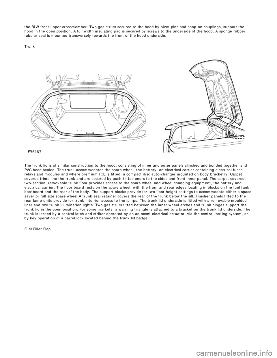
Trunk
The trunk lid is of similar construction to the hood, consisting of inner and outer panels clinched and bonded together and
PVC bead sealed. The trunk accommodates the spare wheel, the battery, an electrical carrier containing electrical fuses,
relays and modules and where premium ICE is fitted, a compac t disc auto-changer mounted on body bracketry. Carpet
covered trims line the trunk and are secured by push-fit fasten ers to the sides and front inner panel. The carpet covered,
two-section, removable trunk floor prov ides access to the spare wheel and wheel changing equipment, the battery and
electrical carrier. The floor board rests on the spare wheel, with the front and rear e dges locating in blocks on the fuel tank
backboard and the rear of the body. The support blocks provide for two floor height settings to accommodate either a space
saver or full size spare wheel.A trunk seal retainer covers the re ar of the trunk below the sill. Finisher panels fitted to the
rear lamp units provide for trunk inte rior access to the lamps. The trunk lid underside is fitted with a removable moulded
liner and two trunk illumination lights. Two gas struts fitted between the inner wheel arches and trunk hinges support the
trunk lid in the open position. For some markets, a warning triangle is attached to a bracket on the trunk lid underside. The
trunk is locked by a central latch and stri ker operated by an adjacent electrical actuator, via the central locking system, or
by key operation of a barrel lock located behind the trunk lid badge.
Fuel Filler Flap
Page 2045 of 2490
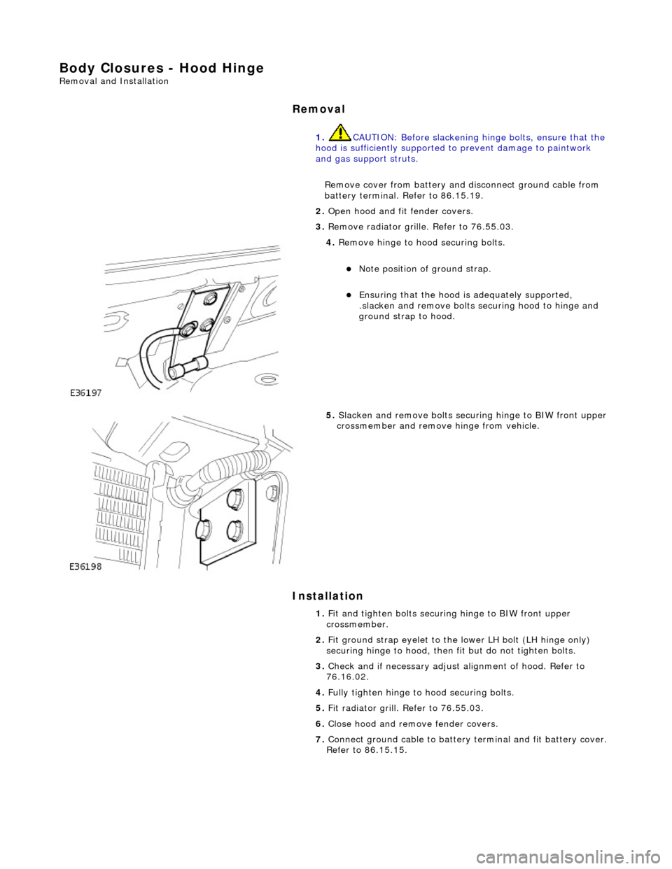
Body Closures - Hood Hinge
Removal and Installation
Removal
Installation
1.
CAUTION: Before slackening hi nge bolts, ensure that the
hood is sufficiently supported to prevent damage to paintwork
and gas support struts.
Remove cover from battery and disconnect ground cable from
battery terminal. Refer to 86.15.19.
2. Open hood and fit fender covers.
3. Remove radiator grille. Refer to 76.55.03.
4. Remove hinge to hood securing bolts.
Note position of ground strap.
Ensuring that the hood is adequately supported,
.slacken and remove bolts se curing hood to hinge and
ground strap to hood.
5. Slacken and remove bolts securi ng hinge to BIW front upper
crossmember and remove hinge from vehicle.
1. Fit and tighten bolts securing hinge to BIW front upper
crossmember.
2. Fit ground strap eyelet to the lower LH bolt (LH hinge only)
securing hinge to hood, then fit but do not tighten bolts.
3. Check and if necessary adjust alignment of hood. Refer to
76.16.02.
4. Fully tighten hinge to hood securing bolts.
5. Fit radiator grill. Refer to 76.55.03.
6. Close hood and remove fender covers.
7. Connect ground cable to battery terminal and fit battery cover.
Refer to 86.15.15.
Page 2386 of 2490
Body Structure
Introduction
The standard wheelbase Jaguar sedan has a unit construction monocoque body structure with bolt-on front fenders and
welded rear fenders. The doors feature lif t-off hinges and welded drop-glass frames.
Constructional Steel Classification
BODY ALIGNMENT
The Body Dimensions Plan, and Body Dimensions Side View, provide specified BIW dimensions to facilitate damage
assessment and location of replacemen t parts. These dimensions must be strictly applied when used for damage
assessment, component location or post repair verification.
• NOTE: The right-hand side is always looking towards the front, from the rear of the vehicle.
The nominated plan view master datums are on the right-hand side of the body with the left-hand datums dimensioned
from them. Right-hand datums must therefore be known to be correct before any other cross-car dimensions are checked.
Datum location, Example
The Front Master Datum (front crossmember rear mounting at the inner face of the main floor RH longitudinal) is nominally
359,5mm to the right-hand side of the body center line. The LH side fron t datum is measured 717,0 / 721,0mm from the
RH. Refer to the Body Dimensions Plan.
Expressed as a true posi tion in three planes, the front master datum is:
Standard Wheelbase Bo dy Dimensions-Plan
MaterialApplication
High strength low alloy
(HLSA).Impact prone areas, ie. seat frame and bumper mountings.
Double sided zinc plated mild steel.Exterior body panels subject to severe cond itions such as stone chipping and weather
exposure (excluding roof panel).
Boron steelDoor intrusion beams
Mild steel.Internal brackets, fill ets and strengtheners.
DatumLocationPosition
Front Master Datum
PlanCentre line of the front crossmember rear mounting, at the main floor RH
longitudinalX
300,0
Y 359,5 Z -50,0
Page 2387 of 2490
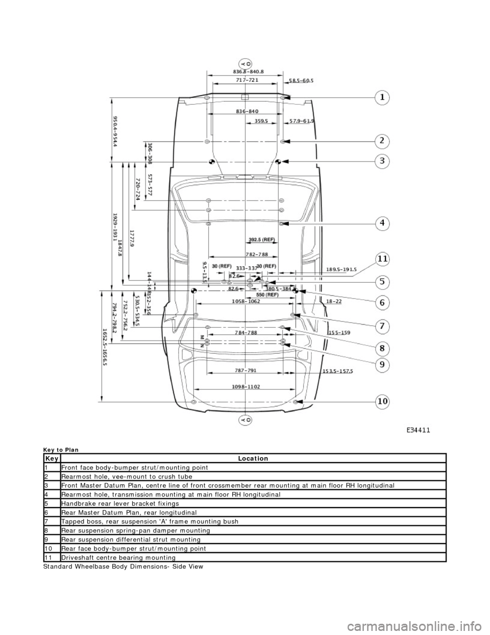
Key to Plan
Standard Wheelbase Body Dimensions- Side View
KeyLocation
1Front face body-bumper strut/mounting point
2Rearmost hole, vee-mount to crush tube
3Front Master Datum Plan, centre li ne of front crossmember rear mount ing at main floor RH longitudinal
4Rearmost hole, transmission mounting at main floor RH longitudinal
5Handbrake rear lever bracket fixings
6Rear Master Datum Plan, rear longitudinal
7Tapped boss, rear suspension 'A' frame mounting bush
8Rear suspension spring-pan damper mounting
9Rear suspension differential strut mounting
10Rear face body-bumper strut/mounting point
11Driveshaft centre bearing mounting