error JAGUAR X308 1998 2.G Workshop Manual
[x] Cancel search | Manufacturer: JAGUAR, Model Year: 1998, Model line: X308, Model: JAGUAR X308 1998 2.GPages: 2490, PDF Size: 69.81 MB
Page 462 of 2490
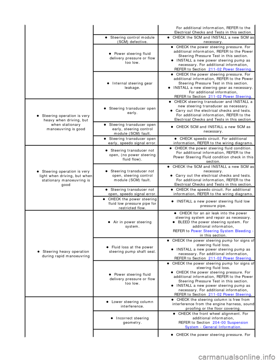
Fo
r additional information, REFER to the
Electrical Checks and Tests in this section.
Steering control
module
(SCM) defective.
CHECK
the SCM and INSTALL a new SCM as
necessary.
Power steeri ng f
luid
delivery pressure or flow too low.
CHECK
the power stee
ring pressure. For
additional information, REFER to the Power Steering Pressure Test in this section.
INSTALL a ne
w power steering pump as
necessary. For additi onal information,
REFER to Section 211
-0 2
Power Steering
.
Internal steering gear
leakage.
CHECK
the power stee
ring pressure. For
additional information, REFER to the Power Steering Pressure Test in this section.
INSTALL a ne
w steering
gear as necessary.
For additional information,
REFER to Section 211
-0 2
Power Steering
.
Steeri
ng operati
on is very
heavy when driving, but when stationary
manoeuvring is good
Steering transducer open earl
y.
CHECK
steering transducer and INSTALL a
new steering transducer as necessary.
Carry out th
e electrical checks and tests.
For additional information, REFER to the
Electrical Checks and Tests in this section.
Steering transducer open
early,
steering control
module (SCM) fault.
CHECK
SCM and INSTALL a new SCM as
necessary.
Steering transducer open
earl
y, speedo signal error.
CHECK
speedo
circui
t. For additional
information, REFER to the wiring diagrams.
Steeri ng operati
on is very
light when driving, but when
stationary manoeuvring is good
Steering transducer not
o
pen, (no power steering
fluid flow).
CHECK
the power steering fluid condition.
For additional information, REFER to the
Power Steering Fluid condition check in this section.
Steering transducer not o
pen, steering control
module (SCM) fault.
CHECK
the SCM and INSTALL a new SCM as
necessary.
Carry out th
e electrical checks and tests.
For additional information, REFER to the
Electrical Checks and Tests in this section.
Steering transducer not
o
pen, speedo signal error.
CHECK
the speedo circ
uit. For additional
information, REFER to the wiring diagrams.
CHECK
the power steering
fluid low pressure pipe for restricted flow.
INSTALL a ne
w power steering fluid low
pressure pipe.
S t
eering heavy operation
during rapid manoeuvring
Ai r i
n power steering
system.
CHECK for an air l
eak into the power
steering system and re pair as necessary.
BLEED the
power steering system. For
additional information,
REFER to Power Steering System Bleeding
- in t hi
s section.
Fluid loss at the power
steering pump shaft seal.
CHECK the power steer
ing pump for signs o
f steering fl
ui
d loss.
INST
ALL a ne
w power steering pump as
necessary. For additi onal information,
REFER to Section 211
-0 2
Power Steering
.
Power steeri
ng f
luid
delivery pressure or flow too low.
CHECK the power steer
ing pump for signs o
f steering fl
ui
d loss.
CHECK
the power stee
ring pressure. For
additional information, REFER to the Power Steering Pressure Test in this section.
INSTALL a ne
w power steering pump as
necessary. For additi onal information,
REFER to Section 211
-02
Power Steering
.
Lower steeri
ng col
umn
interference.
CHECK
the steering co
lumn is free from
interference from the en gine harness, sound
proofing or the floor covering.
Incorrect steering geometry. CHE
CK the front wheel alignment. For
additional information,
REFER to Section 204
-00 Sus
pension
Sy
ste
m
- General
Information
.
CHECK
the power stee
ring pressure. For
Page 522 of 2490
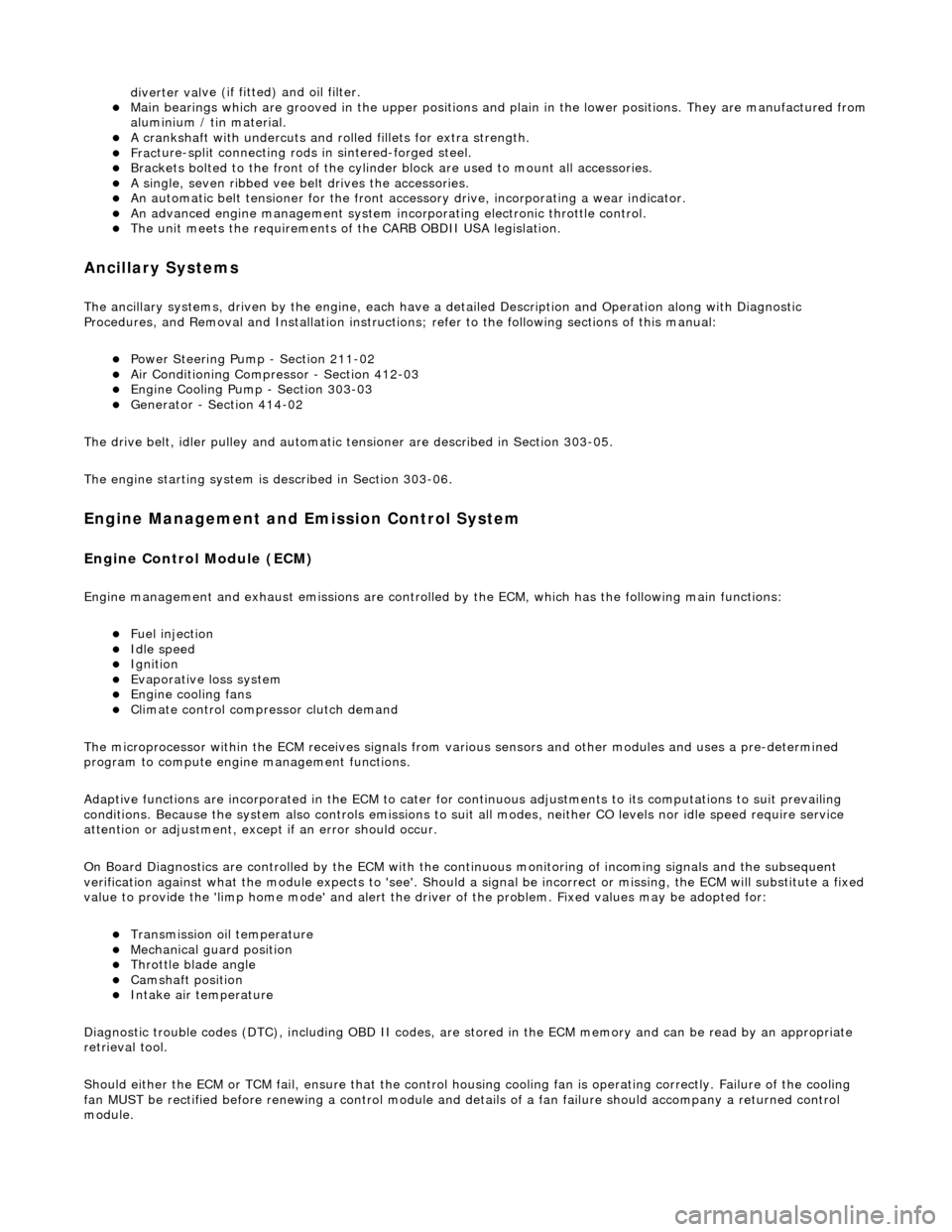
diverter val
ve (if fitted) and oil filter.
Main
bearings
which are grooved in the upper positions and plain in
the lower positions. They are manufactured from
aluminium / tin material.
A c
rankshaft with under
cuts and rolled fillets for extra strength.
Fracture
-split connecting rods in sintered-forged steel.
Brackets
bolted to the front of
the cylinder
block are used to mo unt all accessories.
A sin
gle, seven ribbed vee belt
drives the accessories.
An au
tomatic belt tensioner for the front accessory drive,
incorporating a wear indicator.
An advanced en
gine management system inco
rporating electronic throttle control.
The un
it meets the requirements of the CARB OBDII USA legislation.
Ancillary Systems
The an
ci
llary systems, driven by the engine, each have a
detailed Description and Operation along with Diagnostic
Procedures, and Removal and Installation instructions ; refer to the following sections of this manual:
Power Steeri
ng Pump - Section 211-02
Ai
r Conditioning Compressor - Sectio
n 412-03
Engine
C
ooling Pump - Section 303-03
Generator
- Sectio
n 414-02
The drive belt, idler pulley and automatic tensioner are described in Section 303-05.
The engine starting system is described in Section 303-06.
En
gine Management and Emission Control System
Engine Control Modu
le (ECM)
Engine
management and exhaust emissions are controlled by the ECM, which has the
following main functions:
Fu
el injection
Idle
s
peed
Ignition Ev
aporative loss system
Engine
cooling fans Clim
ate control compressor clutch demand
The microprocessor within the ECM receiv es signals from various sensors and other modules and uses a pre-determined
program to compute engine management functions.
Adaptive functions are incorporated in the ECM to cater for co ntinuous adjustments to its computations to suit prevailing
conditions. Because the system also controls emissions to suit all modes, neither CO levels nor idle speed require service
attention or adjustment, except if an error should occur.
On Board Diagnostics are controlled by the ECM with the continuous monitoring of incoming signals and the subsequent
verification against what the module expects to 'see'. Should a si gnal be incorrect or missing, the ECM will substitute a fixed
value to provide the 'limp home mode' and alert the driver of the problem. Fixed values may be adopted for:
Transmission oil
temperature
Mechanica
l
guar
d position
Throttle blade angle Camshaft position
Inta
k
e air temperature
Diagnostic trouble codes (DTC), including OBD II codes, are stored in the ECM memo ry and can be read by an appropriate
retrieval tool.
Should either the ECM or TCM fa il, ensure that the control housing cooling fan is operating correctly. Failure of the cooling
fan MUST be rectified before renewing a control module and details of a fa n failure should accompany a returned control
module.
Page 1027 of 2490
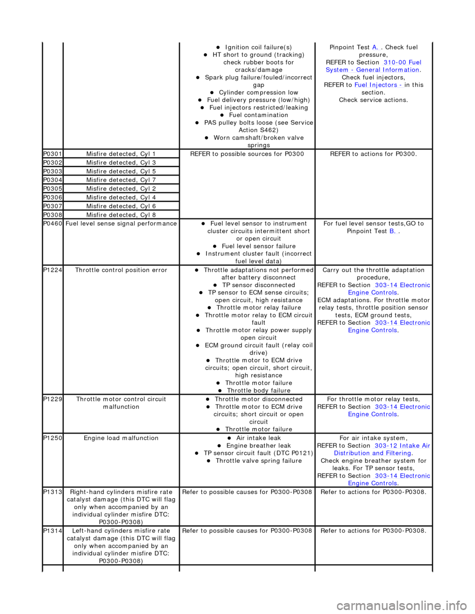
Ignition coil
failure(s)
HT sho
rt to ground (tracking)
check rubber boots for cracks/damage
Spark plug
failure/fouled/incorrect
gap
Cy
linder compression low
F
uel delivery pressure (low/high)
F
uel injectors restricted/leaking
Fuel contamination
P
AS pulley bolts loose (see Service
Action S462)
W
orn camshaft/broken valve
springs
P
inpoint Test
A.
.
Check fuel
pressure,
REFER to Section 310
-00
Fuel
Sy
stem
- General
Information
.
Chec
k fuel injectors,
REFER to Fuel Injectors
- in t
his
section.
Check service actions.
P0301Misfire
detected, Cyl 1
R
EFER to possible sources for P0300
R
EFER to actions for P0300.
P0302Misfire
detected, Cyl 3
P0303Misfire
detected, Cyl 5
P0304Misfire
detected, Cyl 7
P0305Misfire
detected, Cyl 2
P0306Misfire
detected, Cyl 4
P0307Misfire
detected, Cyl 6
P0308Misfire
detected, Cyl 8
P0460F
uel level sense signal performance
Fue
l level sensor
to instrument
cluster circuits in termittent short
or open circuit
F
uel level sensor failure
Instrument cluster
faul
t (incorrect
fuel level data)
F
or fuel level sensor tests,GO to
Pinpoint Test B.
.
P1224Throttl
e control position error
Thro
ttle adaptations not performed
after battery disconnect
TP se
nsor disconnected
TP se
nsor to ECM sense circuits;
open circuit, hi gh resistance
Throttl
e motor relay failure
Th
rottle motor relay to ECM circuit
fault
Throttl
e motor relay power supply
open circuit
ECM ground circuit faul
t (relay coil
drive)
Throttl
e motor to ECM drive
circuits; open circuit, short circuit, high resistance
Throttl
e motor failure
Throttl
e body failure
Carry
out the throttle adaptation
procedure,
REFER to Section 303
-14
Electronic
Engine
Controls
.
ECM adaptations. For
throttle motor
relay tests, throttle position sensor tests, ECM ground tests,
REFER to Section 303
-14
Electronic
Engine
Controls
.
P1229Throttl
e motor control circuit
malfunction
Throttl
e motor disconnected
Throttl
e motor to ECM drive
circuits; short circuit or open circuit
Throttl
e motor failure
Fo
r throttle moto
r relay tests,
REFER to Section 303
-14
Electronic
Engine
Controls
.
P1250Engine
load malfunction
Air
intake leak
Engine
breather leak
TP se
nsor circuit fault (DTC P0121)
Throttl
e valve spring failure
F
or air intake system,
REFER to Section 303
-12
Intake Air
Distribu
tion and Filtering
.
Chec
k engine breather system for
leaks. For TP sensor tests,
REFER to Section 303
-14
Electronic
Engine
Controls
.
P1313Right-hand cylinders misfire rate
cat
alyst damage (this DTC will flag
only when accompanied by an
individual cylinder misfire DTC: P0300-P0308)
R
efer to possible causes for P0300-P0308
R
efer to actions for P0300-P0308.
P1314L
eft-hand cylinders misfire rate
catalyst damage (this DTC will flag only when accompanied by an
individual cylinder misfire DTC: P0300-P0308)
R
efer to possible causes for P0300-P0308
R
efer to actions for P0300-P0308.
Page 1203 of 2490

P1122Acce
lerator pedal position (APP)
sensor circuit 'A' low voltage
A
PP sensor to ECM sense circuit
'A' (sensor pin 5) open circuit or
high resistance
Sensor power su
pply fault
APP s
ensor failure
For APP
sensor circuit tests,GO to
Pinpoint Test R.
, andG
O to Pinpoint
Test S.
.
P1123Acce
lerator pedal position (APP)
sensor circuit 'A' high voltage
A
PP sensor to ECM sense circuit
'A' (sensor pin 5) short circuit to
high voltage
APP s
ensor failure
For APP
sensor circuit tests, GO to
Pinpoint Test R.
, and G
O to Pinpoint
Test S.
.
P1221Acce
lerator pedal position (APP)
sensor circuit 'B'
range/performance
A
PP sensor to ECM sense circuit
'B' (sensor pin 3) open circuit,
short circuit or high resistance
Sensor power su
pply fault
Sensor r
eference ground fault
APP s
ensor failure
For APP
sensor circuit tests,GO to
Pinpoint Test R.
, andG
O to Pinpoint
Test S.
.
P1222Acce
lerator pedal position (APP)
sensor circuit 'B' low voltage
A
PP sensor to ECM sense circuit
'B' (sensor pin 3) open circuit or
high resistance
Sensor power su
pply fault
APP s
ensor failure
For APP
sensor circuit tests,GO to
Pinpoint Test R.
, andG
O to Pinpoint
Test S.
.
P1223Acce
lerator pedal position (APP)
sensor circuit 'B' high voltage
A
PP sensor to ECM sense circuit
'B' (sensor pin 3) short circuit to
high voltage
APP s
ensor failure
For APP
sensor circuit tests,GO to
Pinpoint Test R.
, andG
O to Pinpoint
Test S.
.
P1224Throttl
e control position error
Thro
ttle position adaptations not
performed after ba ttery disconnect
TP se
nsor disconnected
TP se
nsor to ECM sense circuits
open circuit, hi gh resistance
Throttl
e motor power relay failure
Throttl
e motor power relay to ECM
circuit fault
Throttl
e motor power relay power
supply open circuit
ECM ground circuit faul
t (relay coil
drive)
Th
rottle motor to ECM drive circuits
open circuit, short circuit, high
resistance
Throttl
e motor failure
Throttl
e assembly failure
Carry
out throttle adaptation
procedure. For TP sensor circuit
tests,GO to Pinpoint Test D.
, andG
O
to Pinpoint Test K.
. F
or throttle motor
circuit tests,GO to Pinpoint Test T.
.
F
or throttle body information,
REFER to Section 303
-04
Fuel
Charging and Con
trols
.
P1226Mechanica
l guard sensor
range/performance
Mechanica
l guard sensor to ECM
sense circuit open circuit, short
circuit or high resistance
Sensor power su
pply fault
Sensor r
eference ground fault
Mechanica
l guard sensor failure
Mechanica
l guard actuator
seized/spring broken
For mech
anical guard circuit tests,GO
to Pinpoint Test U.
. F
or sensor power
supply circuit tests,GO to Pinpoint
Test V.
. F
or sensor ground circuit
tests,GO to Pinpoint Test W.
. For
throttle body i
nformation,
REFER to Section 303
-04
Fuel
Charging and Con
trols
.
P1227Mechanica
l guard sensor circuit
low voltage
Mechanica
l guard sensor to ECM
sense circuit open circuit or high
resistance
Sensor power su
pply fault
Mechanica
l guard sensor failure
For mech
anical guard circuit tests,GO
to Pinpoint Test U.
. F
or sensor power
supply circuit tests,GO to Pinpoint
Test V.
. F
or throttle body
information,
REFER to Section 303
-04
Fuel
Charging and Con
trols
.
P1228Mechanica
l guard sensor circuit
high voltage
Mechanica
l guard sensor to ECM
sense circuit short circuit to high
voltage
Mechanica
l guard sensor failure
For mech
anical guard circuit tests,GO
to Pinpoint Test U.
. F
or throttle body
information,
REFER to Section 303
-04
Fuel
Charging and Con
trols
.
P1229Throttl
e motor control circuit
mallfunction
Throttl
e motor disconnected
Th
rottle motor to ECM drive circuits
short circuit or open circuit
Throttl
e motor failure
Fo
r throttle motor circuit tests,GO to
Pinpoint Test T.
.
P1230Fue
l pump relay malfunction.
NOTE. This DTC covers the S/C
system fuel pump 1
F
uel pump relay failure
F
uel pump to ECM circuit fault
F
uel pump relay coil power supply
F
or fuel pump relay circuit tests,
REFER to Section 303
-04
Fuel
Charging and Con
trols
.
Page 1222 of 2490
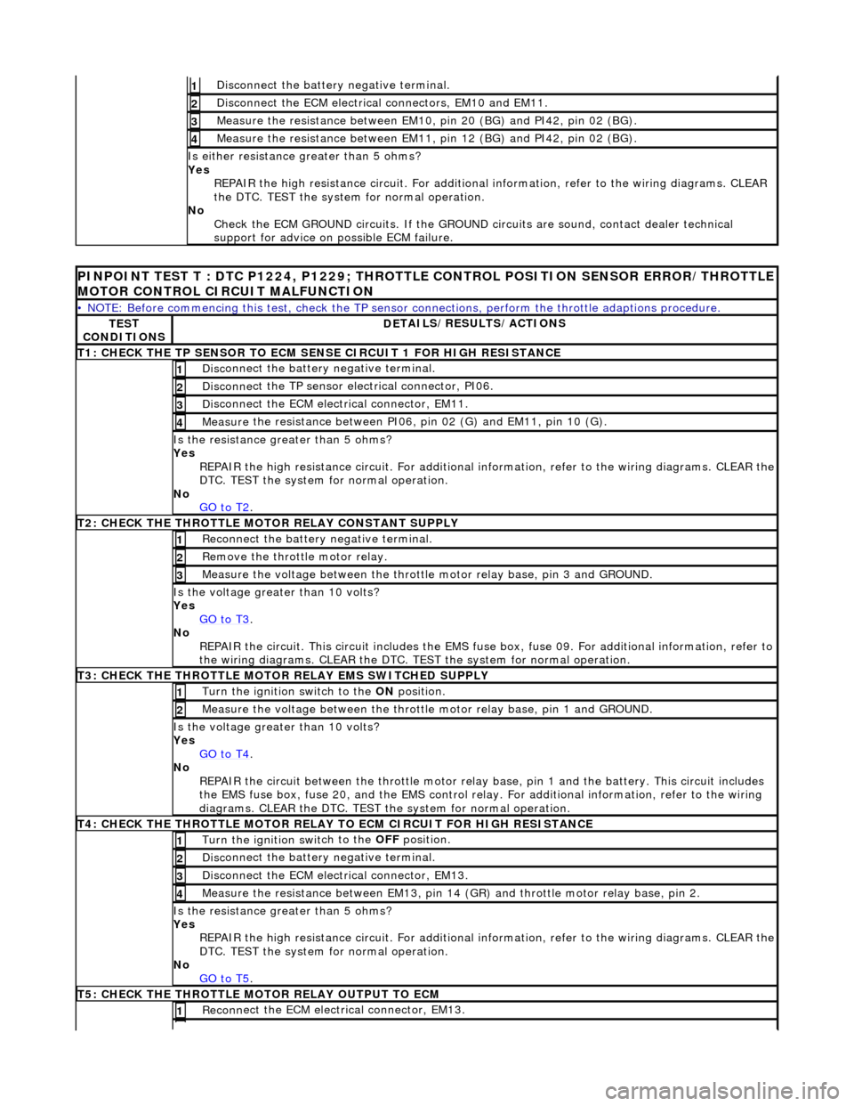
Disc
onnect the battery negative terminal.
1
D
i
sconnect the ECM electrical connectors, EM10 and EM11.
2
Meas
ure t
he resistance between EM10,
pin 20 (BG) and PI42, pin 02 (BG).
3
Measure t
he resistance between EM11,
pin 12 (BG) and PI42, pin 02 (BG).
4
Is either resistance greater
than 5 ohms?
Yes REPAIR the high resistance circui t. For additional information, refer to the wiring diagrams. CLEAR
the DTC. TEST the system for normal operation.
No Check the ECM GROUND circuits. If the GROUND circuits are sound, contact dealer technical
support for advice on possible ECM failure.
PINPOINT TES
T T : DTC P1224, P1229; THROTTLE
CONTROL POSITION SENSOR ERROR/THROTTLE
MOTOR CONTROL CIRCUIT MALFUNCTION
•
NOTE: Before commencing this test, check the TP sensor
connections, perform the throttle adaptions procedure.
TES
T
CONDITIONS
D E
TAILS/RESULTS/ACTIONS
T
1: CH
ECK THE TP SENSOR TO ECM SE
NSE CIRCUIT 1 FOR HIGH RESISTANCE
Disc
onnect the battery negative terminal.
1
Disc
onne
ct the TP sensor electrical connector, PI06.
2
D
i
sconnect the ECM electrical connector, EM11.
3
Me
asure
the resistance between PI06, pin 02 (G) and EM11, pin 10 (G).
4
Is th
e res
istance greater than 5 ohms?
Yes REPAIR the high resistance circuit. For additional information, refer to the wiring diagrams. CLEAR the
DTC. TEST the system for normal operation.
No GO to T2
.
T2
: CHECK THE THROTTLE MOTOR RELAY CONSTANT SUPPLY
R
e
connect the battery negative terminal.
1
R
e
move the thrott
le motor relay.
2
Measure t
he voltage between the throttle
motor relay base, pin 3 and GROUND.
3
Is the volt
age greater than 10 volts?
Yes GO to T3
.
No
R
EPAIR the circuit. This ci
rcuit includes the EMS fuse box, fuse 09. For addi tional information, refer to
the wiring diagrams. CLEAR the DTC. TE ST the system for normal operation.
T3
: CHECK THE THROTTLE MOTOR
RELAY EMS SWITCHED SUPPLY
Turn the ignition swit
ch to the
ON position.
1
Meas ure t
he voltage between the throttle
motor relay base, pin 1 and GROUND.
2
Is the volt
age greater than 10 volts?
Yes GO to T4
.
No
REP
AIR the circuit between the throttle motor relay
base, pin 1 and the battery. This circuit includes
the EMS fuse box, fuse 20, and the EMS control relay. For addition al information, refer to the wiring
diagrams. CLEAR the DTC. TEST th e system for normal operation.
T4
: CHECK THE THROTTLE MOTOR RELAY TO
ECM CIRCUIT FOR HIGH RESISTANCE
Turn the ignition swit
ch to the
OFF position.
1
Disc
onnect the battery negative terminal.
2
Di
sconnect the ECM electrical connector, EM13.
3
Measure t
he resistance between EM13, pin 14 (G
R) and throttle motor relay base, pin 2.
4
Is the res
istance greater than 5 ohms?
Yes REPAIR the high resistance circuit. For additional information, refer to the wiring diagrams. CLEAR the
DTC. TEST the system for normal operation.
No GO to T5
.
T5
: CHECK THE THROTTLE MOTOR RELAY OUTPUT TO ECM
Re
conn
ect the ECM electrical connector, EM13.
1
Page 1400 of 2490
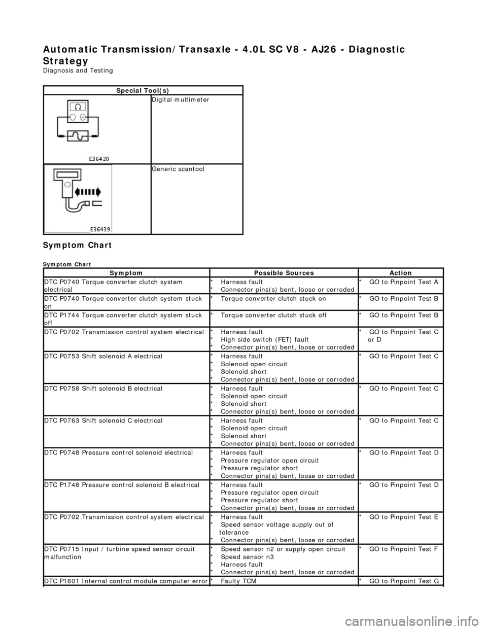
Automatic Transmission/Transaxle - 4.0L SC V8 - AJ26 - Diagnostic
Strategy
Diagnosis and Testing
Symptom Chart
Symptom Chart
Special Tool(s)
Digital multimeter
Generic scantool
SymptomPossible SourcesAction
DTC P0740 Torque converter clutch system
electricalHarness fault
Connector pins(s) bent , loose or corroded
*
*GO to Pinpoint Test A
*
DTC P0740 Torque converter clutch system stuck
onTorque converter clutch stuck on
*GO to Pinpoint Test B
*
DTC P1744 Torque converter clutch system stuck
offTorque converter clutch stuck off
*GO to Pinpoint Test B
*
DTC P0702 Transmission control system electricalHarness fault
High side switch (FET) fault
Connector pins(s) bent , loose or corroded
*
*
*GO to Pinpoint Test C
or D
*
DTC P0753 Shift solenoid A electricalHarness fault
Solenoid open circuit
Solenoid short
Connector pins(s) bent
, loose or corroded
*
*
*
*GO to Pinpoint Test C *
DTC P0758 Shift solenoid B electricalHarness fault
Solenoid open circuit
Solenoid short
Connector pins(s) bent
, loose or corroded
*
*
*
*GO to Pinpoint Test C *
DTC P0763 Shift solenoid C electricalHarness fault
Solenoid open circuit
Solenoid short
Connector pins(s) bent
, loose or corroded
*
*
*
*GO to Pinpoint Test C *
DTC P0748 Pressure control solenoid electricalHarness fault
Pressure regulator open circuit
Pressure regulator short
Connector pins(s) bent
, loose or corroded
*
*
*
*GO to Pinpoint Test D *
DTC P1748 Pressure control solenoid B electricalHarness fault
Pressure regulator open circuit
Pressure regulator short
Connector pins(s) bent
, loose or corroded
*
*
*
*GO to Pinpoint Test D *
DTC P0702 Transmission control system electricalHarness fault
Speed sensor voltage supply out of
tolerance Connector pins(s) bent , loose or corroded
*
*
*GO to Pinpoint Test E
*
DTC P0715 Input / turbine speed sensor circuit
malfunctionSpeed sensor n2 or supply open circuit
Speed sensor n3
Harness fault
Connector pins(s) bent , loose or corroded
*
*
*
*GO to Pinpoint Test F
*
DTC P1601 Internal control module computer errorFaulty TCM
*GO to Pinpoint Test G *
Page 1470 of 2490

Move the selector lever slowly from P to 2 and back,
noting the illumination / positi on relationship as follows: 1
Does state illumination match the lever position in each
direction of travel?
Yes
GO to A4
No GO to A3
No With lever at D (when moving from 2 to P ) is 3 or 4
illuminated?
Yes GO to A3
No GO to A5
No With lever moved from P , to position 4 , is D illuminated?
Yes GO to A4
No GO to A5
A3: CHECK SELECTOR CABLE ADJUSTMENT
Verify and correct as requ ired the selector cable
adjustment 1
OK?
Yes GO to A4
No Correct adjustment error, see 44.15.07 Workshop Manual
307-05A and test the system for normal operation.
A4: CHECK HARNESS SIGNAL CONTINUITY - D TO 4 SWITCH
Page 1504 of 2490

Automatic Transmission/Transaxle External Controls - 4.0L SC V8 - AJ26 -
External Controls
Diagnosis and Testing
Problem Solving - Transmission Shift
Quick Reference Fault Chart
Special Tool(s)
Digital multimeter
Generic scan tool
SymptomPossible SourcesAction
Shift stuck in P Selector cable seized
*GO to 44.15.08
*
Interlock solenoid not operating
*GO to PDU
*
Interlock latch seized
Transmission faulty
*
*Mechanical check
*
Operator sequence error
*Correct the sequence
*
Vehicle rolls on P Incorrect cable adjustment
*GO 44.15.07
*
Faulty parking pawl (transmission internal)
*Mechanical check
*
R does not engageIncorrect cable adjustment
*GO to 44.15.07
*
Transmission fluid level incorrect
*GO to 44.24.02
*
N not achievedIncorrect cable adjustment
Transmission faulty
*
*GO to 44.15.07
*
D does not engageIncorrect cable adjustment *GO to 44.15.07
*
Transmission fluid level incorrect
*GO to 44.24.02
*
Transmission faulty
*Mechanical check
*
Lower ratios will not holdExcessive engine temperature
DLS fault
*
*GO to PDU
*
Shift lever position not visually correctIncorrect DLS adjustment
*GO to 44.15.07
*
Shift lever has no effect upon the
transmission and resistance cannot be
feltCable disconnected or broken
Transmission selector problem
Shift lever drive pin adrift
*
*
*Mechanical check
*
Shift lever position not align correctly
following manual selection of lower
ratiosSliding block drive pin displaced - following road debris contact
*Mechanical check. Renew the selector if
damaged, or re-align the drive pin and
sliding block
*
Shift lever detent indistinct in 3
causing poor locationDLS detent fault
*GO to Renew the DLS
*
Shift may be moved from P without
brake pedal operationInterlock latch fault
*Mechanical check
*
Solenoid permanently activated
*GO to PDU
*
Engine may be started in positions
other than P or N Incorrect cable adjustment
DLS fault
*
*GO to 44.15.07
*
Shift lever vibrationLoose selector assembly
Cable isolation fault
*
*Mechanical check
*
Noise / rattle from 'J' gateDebris in the mechanism
*Clean
*
Worn 'J' gate track gasket
allowing lever and moulding to
contact
*GO to 44.15.05
*
Page 1506 of 2490

No GO to A5
No With lever moved from P , to position 4 , is D illuminated?
Yes GO to A4
No GO to A5
A3: CHECK SELECTOR CABLE OR LINEAR SWITCH ADJUSTMENT
Verify and correct as required the selector cable or linear
switch adjustment 1
OK?
Yes GO to A4
No Correct adjustment error, see 44.15.07 Workshop Manual
307-05B and test the system for normal operation.
A4: CHECK HARNESS SIGNAL CONT INUITY - DUAL LINEAR SWITCH
With EM0 61 and CC008 disconnected, measure the
resistance between CC00 8/001 and EM061 /028
Repeat for
1
CC008/008 and EM061/027 2
CC008/006 and EM061/026 3
CC008/007 and EM061/025 4
Is the resistance < 0.5 OHM?
Yes GO to A5
No Inspect EM061, EM063 and CC008 for corrosion, bent /
pushed back pins or locate harness. Repair as necessary
and test the system for normal operation.
A5: CHECK HARNESS SWITCH GROUND CONTINUITY
Page 1799 of 2490
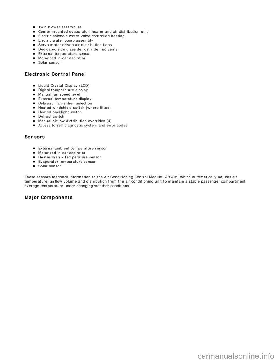
Twin blower assemblies Center mounted evaporator, heater and air distribution unit Electric solenoid water valve controlled heating Electric water pump assembly Servo motor driven air distribution flaps Dedicated side glass defrost / demist vents External temperature sensor Motorised in-car aspirator Solar sensor
Electronic Control Panel
Liquid Crystal Display (LCD) Digital temperature display Manual fan speed level External temperature display Celsius / Fahrenheit selection Heated windshield switch (where fitted) Heated backlight switch Defrost switch Manual airflow distribution overrides (4) Access to self diagnostic system and error codes
Sensors
External ambient temperature sensor Motorized in-car aspirator Heater matrix temperature sensor Evaporator temperature sensor Solar sensor
These sensors feedback information to the Air Conditioning Control Module (A/CCM) which automatically adjusts air
temperature, airflow volume and distributi on from the air conditioning unit to maintain a stable passenger compartment
average temperature under changing weather conditions.
Major Components