Relay JAGUAR X308 1998 2.G Owners Manual
[x] Cancel search | Manufacturer: JAGUAR, Model Year: 1998, Model line: X308, Model: JAGUAR X308 1998 2.GPages: 2490, PDF Size: 69.81 MB
Page 1719 of 2490

W
ith EM013 disconnected, measure the resistance
between EM013/009 and relay socket pin 1
1
I
s the resistance < 0.5 OHM?
Yes GO to B9
No Inspect connectors EM013, EM051/008, LS003/21,
BT004/009 and BT010/005 for corrosion, damage, bent or
pushed back pins and repair as required. Test the system
for normal operation
B9: CHECK
ECM GROUND CONTINUITY
Page 1720 of 2490

Wi
th EM014 disconnected, measure the resistance
between EM014/010 and ground EM016L.
1
I s
the resistance < 0.5 OHM?
Yes STOP, renew the relay and test the system for normal
operation.
No Inspect harness / connectors EM014, splice EMS37 and
ground EM016L for corrosion, damage, bent or pushed
back pins. Repair as requir ed and test the system for
normal operation.
B10: CHECK FU EL
PUMP CONTINUITY
Page 1723 of 2490

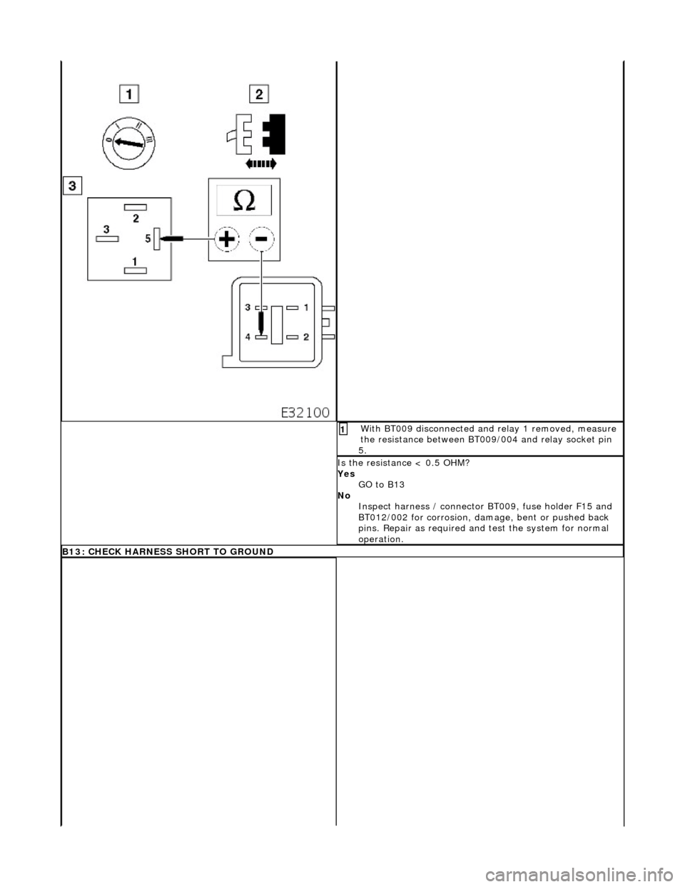
Wi
th BT009 disconnected an
d relay 1 removed, measure
the resistance between BT009/004 and relay socket pin
5.
1
I
s the resistance < 0.5 OHM?
Yes GO to B13
No Inspect harness / connector BT 009, fuse holder F15 and
BT012/002 for corrosion, damage, bent or pushed back
pins. Repair as required and test the system for normal
operation.
B13: CHECK HARNESS SHO
RT TO GROUND
Page 1724 of 2490

Wi
th EM013 and BT009 disconnected, measure the
insulation resistance between EM013/009 and ground
BT020L.
1
I s
the resistance > 10M OHM?
Yes Do not replace relay or reconnect connectors
GO to B14
No Inspect harness / connec tors EM013, EM051/008,
LS003/021, BT004/009 and BT010/005 for corrosion,
damage, bent or pushed back pins. Repair as required
and test the system for normal operation.
B1 4
: CHECK CORE TO CORE INSULATION
Page 1725 of 2490

With
conditions as B13, meas
ure the insulation resistance
between EM013/009 and relay socket pin 5.
1
I
s the resistance > 10M OHM?
Yes GO to B16
No Inspect harness / connec tors EM013, EM051/008,
LS003/021, BT004/009, BT012/002, BT009/004 and
BT010/005 for corrosion, damage, bent or pushed back
pins and repair as required. Test the system for normal
operation
B1
5: CHECK CORE TO CORE INSULATION
Page 1726 of 2490

Pinpoint test C: P0460
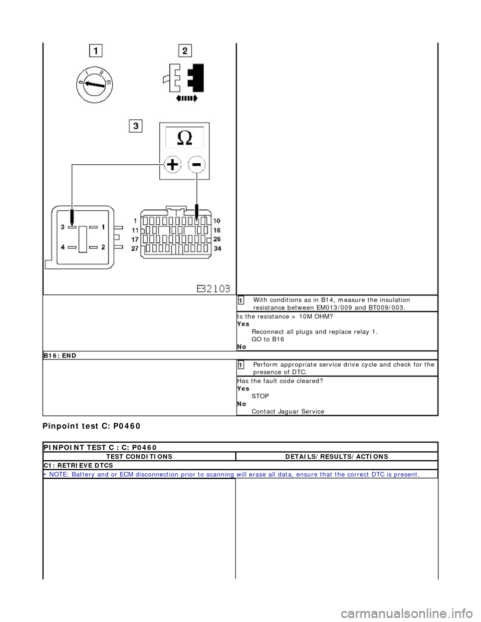
Wi
th conditions as in B14, measure the insulation
resistance between EM013/009 and BT009/003.
1
I s
the resistance > 10M OHM?
Yes Reconnect all plugs and replace relay 1.
GO to B16
No
B 16:
END
Perform
a
ppropriate service drive cycle and check for the
presence of DTC.
1
Has th
e fault code cleared?
Yes STOP
No Contact Jaguar Service
PI
NPOINT TEST C : C: P0460
T
E
ST CONDITIONS
D
E
TAILS/RESULTS/ACTIONS
C1
: RETRIEVE DTC
S
•
NOTE
: Battery and or ECM disconnection prior to scanning wi
ll erase all data, ensure that the correct DTC is present.
Page 1800 of 2490

Compressor:
Features
Engine mounted, driven by the accessory drive belt. Fixed displacement type. High-pressure relief valve, to avoid system over-pressure. ECM controlled clutch energized via a relay.
Receiver drier:
Vertically mounted on the ri ght-hand side of the engine compartment next to the engine coolant radiator. Fitted with the high-side charge port. Includes a fluorescent tracer dye me chanism to aid leak detection.
ItemPart NumberDescription
1—Compressor assembly
2—Condenser
3—Evaporator and heater matrix (internal)
4—Receiver drier
5—4-level pressure switch
6—Expansion valve (internal)
7—High-side charge port
8—Low-side charge port
9—Suction muffler
10—Discharge hose
11—Discharge pipe
12—Suction hose
13—Suction pipe
14—Liquid line
15—Jumper hose (condenser hose)
Page 1831 of 2490

other sensors. This feature prevents the effects of sudden changes in air outlet temperatures due to factors such as:
Recirculating air from the engine cooling pack at low vehicle speeds Sudden changes in ambient temperature The effects of water splash
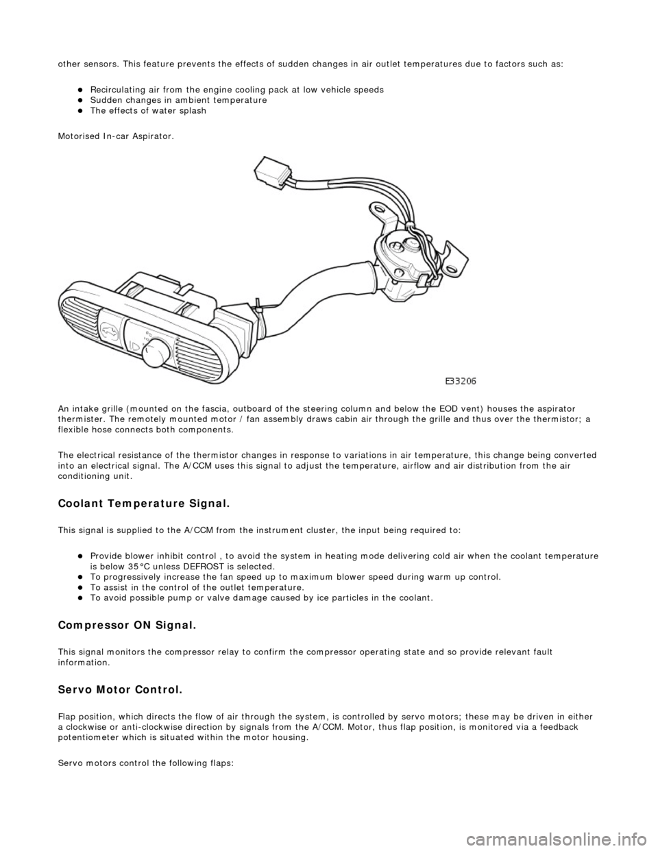
Motorised In-car Aspirator.
An intake grille (mounted on the fascia , outboard of the steering column and below the EOD vent) houses the aspirator
thermister. The remotely mounted motor / fan assembly draws ca bin air through the grille and thus over the thermistor; a
flexible hose connects both components.
The electrical resistance of the thermistor changes in response to variations in air temperatur e, this change being converted
into an electrical signal. The A/CCM uses this signal to adjust the temperature, airflow and air distribution from the air
conditioning unit.
Coolant Temperature Signal.
This signal is supplied to the A/CCM from the instrument cluster, the input being required to:
Provide blower inhibit control , to avoid the system in heat ing mode delivering cold air when the coolant temperature is below 35°C unless DEFROST is selected. To progressively increase the fan speed up to maximum blower speed during warm up control. To assist in the control of the outlet temperature. To avoid possible pump or valve damage ca used by ice particles in the coolant.
Compressor ON Signal.
This signal monitors the compressor relay to confirm the compressor operating state and so provide relevant fault
information.
Servo Motor Control.
Flap position, which directs the flow of air through the system, is controlled by servo motors; these may be driven in either
a clockwise or anti-clockwise direction by signals from the A/ CCM. Motor, thus flap position, is monitored via a feedback
potentiometer which is situated within the motor housing.
Servo motors control the following flaps:
Page 1833 of 2490

Control Components - Control Components
Diagnosis and Testing
Connector Pin Identity Chart for AC001
Connector Pin Identity Chart for AC002
Pin NumberCircuitCircuit Function
001Compressor ON signal
002Coolant valve
003RH Blower motor relay
004Heated windshield relays (where fitted)
005Heated door mirror relay
006Defrost servomotor (positive)
007Center vent servomotor (positive)
008LH air intake servomotor fre sh / recirculation (positive)
009RH air intake servomotor fresh / recirculation (positive)
010Not used
011Not used
012Foot servomotor (positive)
013Cool air bypass servomotor (positive)
014Not used
015Not used
016LH Blower motor relay
017Coolant pump motor relay
018Heated backlight relay
019Defrost servomotor (negative)
020Center vent servomotor (negative)
021LH air intake servomotor fresh / recirculation (negative)
022RH air intake servomotor fresh / recirculation (negative)
023Not used
024Not used
025Foot servomotor (negative)
026Cool air bypass servomotor (negative)
Page 1835 of 2490

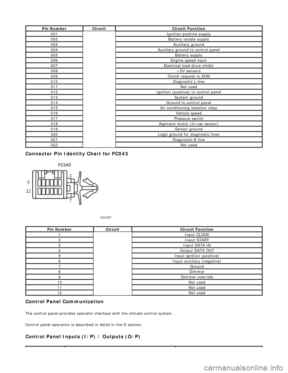
Connector Pin Identity Chart for FC043
Control Panel Communication
The control panel provides operator interface with the climate control system.
Control panel operation is described in detail in the D section.
Control Panel Inputs (I/P) / Outputs (O/P)
Pin NumberCircuitCircuit Function
001Ignition positive supply
002Battery isolate supply
003Auxiliary ground
004Auxiliary ground to control panel
005Battery supply
006Engine speed input
007Electrical load drive inhibit
008+5V sensors
009Clutch request to ECM
010Diagnostic L-line
011Not used
012Ignition (positive) to control panel
013System ground
014Ground to control panel
015Air conditioning isolation relay
016Vehicle speed
017Pressure switch
018Aspirator motor (In-car sensor)
019Sensor ground
020Logic ground for diagnostic lines
021Diagnostic K-line
022Not used
Pin NumberCircuitCircuit Function
1Input CLOCK
2Input START
3Input DATA IN
4Output DATA OUT
5Input ignition (positive)
6Input auxiliary (negative)
7Ground
8Dimmer
9Dimmer override
10Not used
11Not used
12Not used