speed control JAGUAR X308 1998 2.G Owners Manual
[x] Cancel search | Manufacturer: JAGUAR, Model Year: 1998, Model line: X308, Model: JAGUAR X308 1998 2.GPages: 2490, PDF Size: 69.81 MB
Page 1864 of 2490
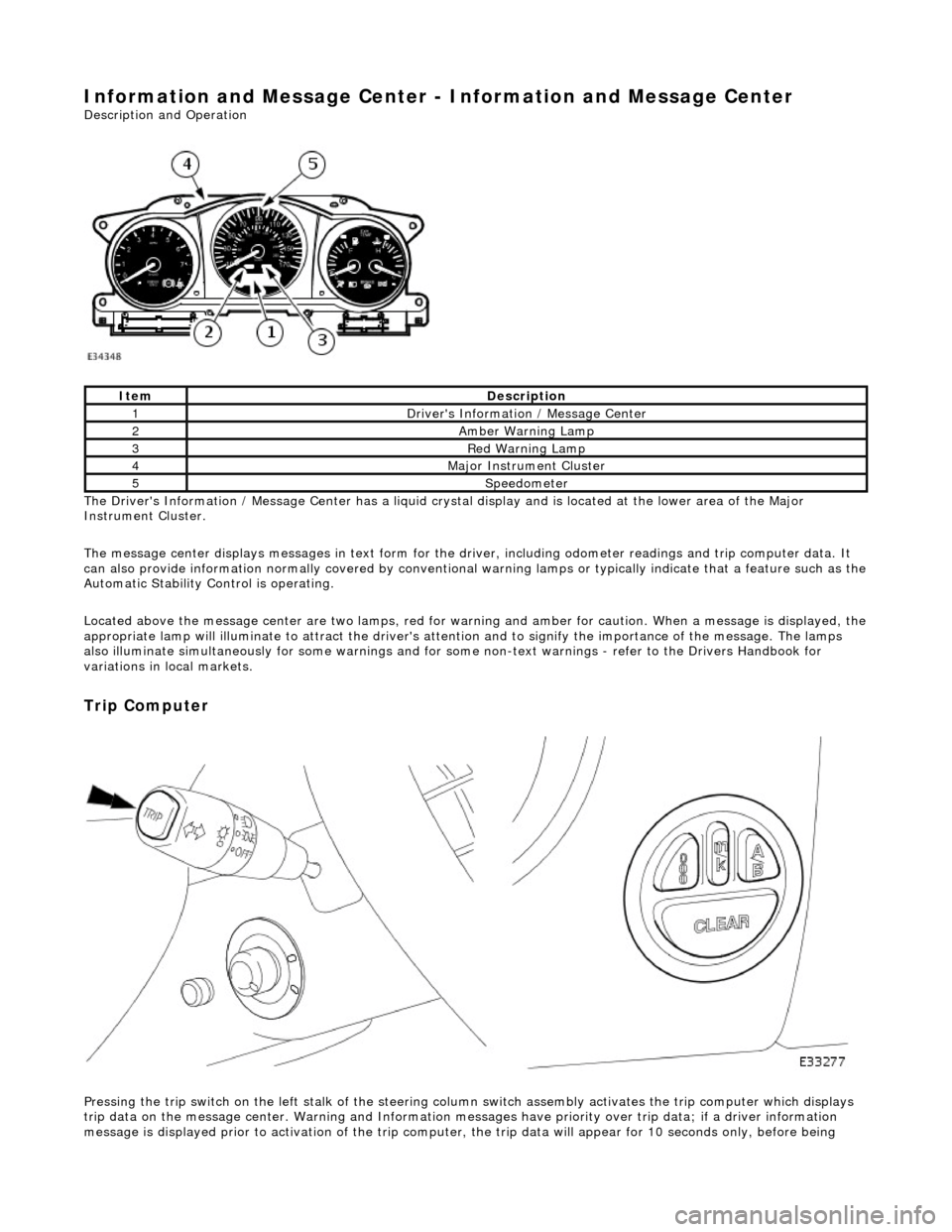
Information and Message Center - Information and Message Center
Description and Operation
The Driver's Information / Message Center has a liquid crystal display and is located at the lower area of the Major
Instrument Cluster.
The message center displays messages in text form for the driver, including odometer readings an d trip computer data. It
can also provide information normally covered by conventional wa rning lamps or typically indicate that a feature such as the
Automatic Stability Control is operating.
Located above the message center are two lamps, red for warning and amber for caution. When a message is displayed, the
appropriate lamp will illuminate to attract the driver's attention and to signify the importance of the message. The lamps
also illuminate simultaneously for some warnings and for some non-text warnin gs - refer to the Drivers Handbook for
variations in local markets.
Trip Computer
Pressing the trip switch on the left stalk of the steering colu mn switch assembly activates the trip computer which displays
trip data on the message center. Warning and Information messages have priority ov er trip data; if a driver information
message is displayed prior to activation of the trip computer , the trip data will appear for 10 seconds only, before being
ItemDescription
1Driver's Information / Message Center
2Amber Warning Lamp
3Red Warning Lamp
4Major Instrument Cluster
5Speedometer
Page 1884 of 2490
The interference suppression module (where fitted) connects to the generator main terminal 'B +' and a ground stud on the
rear face of the generator.
A multi-plug (3 pin) is connecte d to the rear of the generator:
Pin 1 not connected. Pin 2 ignition supply to the regulator. Pin 3 output to the charge warning lamp.
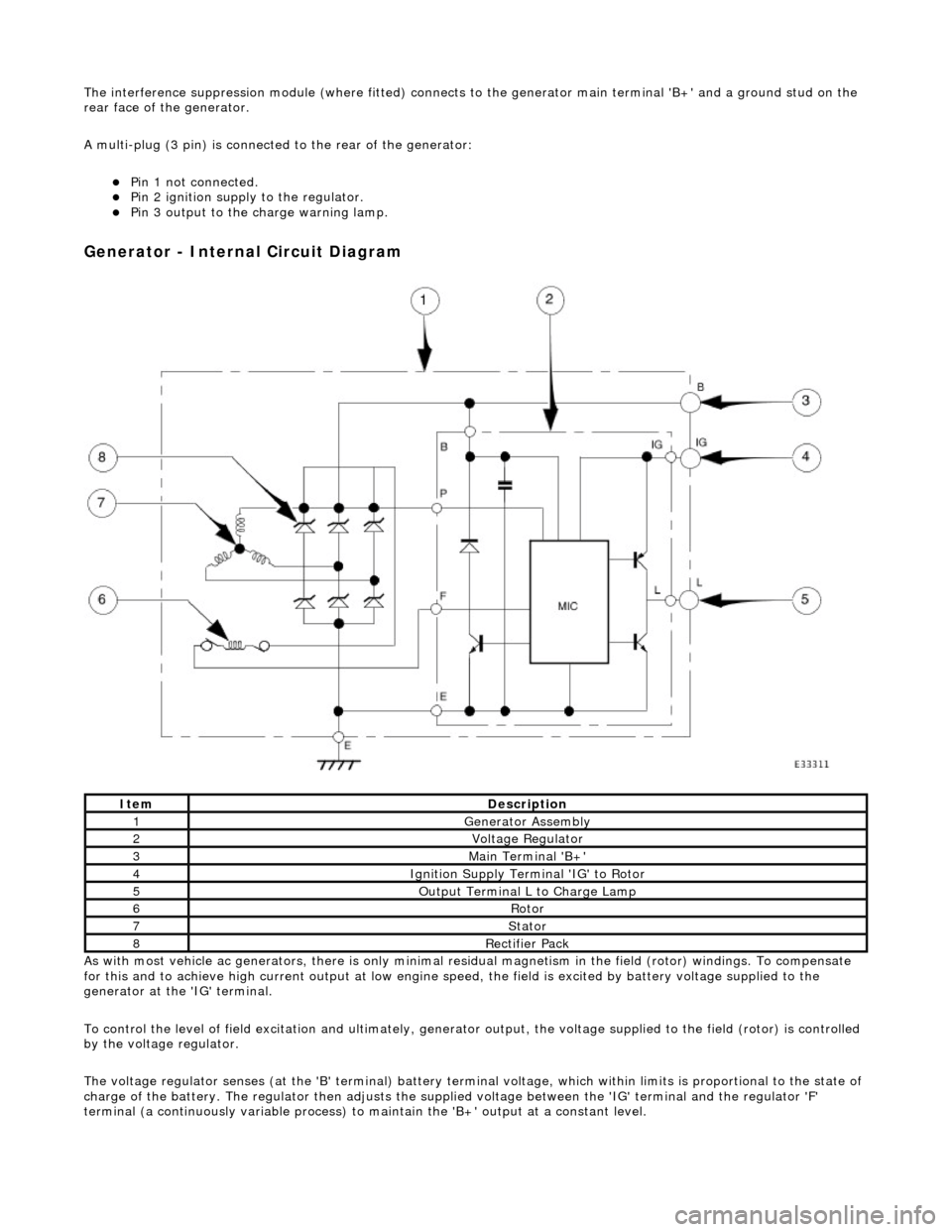
Generator - Internal Circuit Diagram
As with most vehicle ac generators, there is only minimal residual magnet ism in the field (rotor) windings. To compensate
for this and to achieve high current outp ut at low engine speed, the field is excited by battery voltage supplied to the
generator at the 'IG' terminal.
To control the level of field excitation and ultimately, generator output, the voltag e supplied to the field (rotor) is controlled
by the voltage regulator.
The voltage regulator senses (at the 'B' terminal) battery terminal voltage, which within limits is proportional to the state o f
charge of the battery. The regulator then adjusts the supplied voltage between the 'IG' terminal and the regulator 'F'
terminal (a continuously variable process) to maintain the 'B+' output at a constant level.
ItemDescription
1Generator Assembly
2Voltage Regulator
3Main Terminal 'B+'
4Ignition Supply Terminal 'IG' to Rotor
5Output Terminal L to Charge Lamp
6Rotor
7Stator
8Rectifier Pack
Page 1885 of 2490
If the field were not controlled, the 'B+' output would rise to a level which could damage bulbs and ECMs. The regulator
compares the output voltage to an intern al voltage reference circuit to achieve the controlled output of the generator.
Suppression Module
Although the output from the generator is fi nely controlled and relatively smooth, it is still a pulsed DC output at a varying
frequency proportional to engine speed.
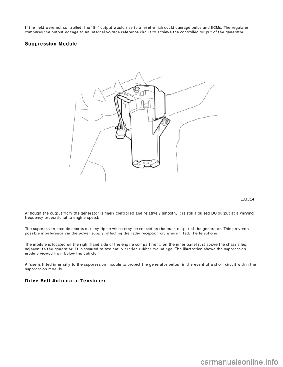
The suppression module damps ou t any ripple which may be sensed on the main output of the generator. This prevents
possible interference via the power supply, affecting the radio reception or, where fitted, the telephone.
The module is located on the right hand side of the engine compartment, on the inner panel just above the chassis leg,
adjacent to the generator. It is secured to two anti-vibration rubber moun tings. The illustration shows the suppression
module viewed from below the vehicle.
A fuse is fitted internally to the suppression module to protect the generator output in the event of a short circuit within th e
suppression module.
Drive Belt Automatic Tensioner
Page 2008 of 2490
Driver Door Module (DDM)
Interior lights circuit
BPM inputs from: BPM outputs to:
Header console courtesy light switch
SCPInstrument and switch illumination. Fade 1 (Header console courtesy lamps) Fade 2 (E-post courtesy lamps) Map lights Sun visor lamps Glovebox lamp Trunk lamps
Washer / wiper circuit
Wiper park switch Low screen wash switch Wiper slow speed switch Wiper fast speed switch Wiper intermittent switch Wash/wipe switch
Power wash relay Wiper motor run Screen wash pump Wiper fast/slow speed
Ignition circuit
Ignition position Auxiliary position Transit relay Mirror fold out Mirror fold flat
Central door locking circuit
Central locking button Valet switch SCP (door modules)
Central door locking relay SCP (door modules, security and locking control
module)
Sun roof ECU
Security system circuit
Hood security switch Horn switches Central locking button SCP (door modules, security and locking control
module)
ISO link (key transponder module)
Horn relay Active security sounder Passive security sounder Security status LED Central door locking relay SCP (door modules, security and locking control
module)
ISO link (key transponder module)
Steering column adjustment circuit
Column adjustment switchesColumn tilt motor Column reach motor
Gear shift interlock circuit
Neutral switch J-gate not in park Keylock solenoid Gearshift interlock solenoid
Seat heaters circuit
Seat heater switchesSeat heater relay Status LED
Seat buckle circuit
Seat buckleAudible warning SCP
Page 2023 of 2490
sliding roof finisher and clips. Carpet covered trims line the trunk and are secured by fir tree fasteners to the sides and fro nt inner panel.
Rear View Mirrors
The.interior rear view mirror is an electrochromic unit that automatically da rkens to prevent glare from following vehicle
lights. This automatic function is selected by pressing the switch at the bottom of the mirror. Pressing the switch again
cancels this function. An LED then illuminates when automatic dipping is operative. The light sensing unit for the Night
Sentinel automatic lamp operating system is also incorporated in the mirror casing.
The door mirrors are cheater mounted, colo r-keyed units, remote electrically adjustable and heated. Adjustment of both
mirrors is carried out from the driver's door switchpack.A slider switch selects the mirror to be adjusted, and a disc switch
adjusts the selected mirror to the required position. Mirror ad justment can only be made when the ignition switch is in
position I or II or the driver's door is open, and the selector switch is moved from the central position. The door mirrors also
automatically darken under control of the electrochromic interior rear view mirror. Mirror heating elements operate on
selection of backlight heating.
Automatic dipping of passenger door mirror for kerb view when reversing, is fitted as part of the memory pack. With the
ignition switch in position II, the mirror selector switch in the left or right position and reverse gear selected, automatic
dipping is initiated by moving the mirror toggle switch rearwards and releasing. On receipt of the dip signal, the passenger
door mirror is driven downwards either 7 degrees, bottom of travel, or 4,5 to 5,5 seconds, whichever occurs first.
Subsequent rearward movement of the toggle switch achieves further dipping of the mirror in the same increments and
sequence. The mirror can be manu ally returned to the normal memorised positi on by moving the toggle switch forward with
reverse gear selected. The mirror will auto matically return to memorised position on deselection of reverse gear, or moving
ignition switch from position II.
Door mirror fold-back where fitted, to facilitate parking in conf ined spaces, can be initiated when the ignition switch is in
position I or II, the mirror selector switch is in the centra l position and vehicle speed is below 19 km/h (12 mph). Mirror
fold-back is then initiated by moving the toggle switch rear wards and releasing it. The door mirrors are returned to the
normal driving position by agai n moving toggle switch rearwards. There is no speed constraint on this operation. In the
event of a fold-back mirror becoming 'out of position' due to acci dental impact, it must only be re-positioned by initiating
the fold-back sequence.
Loss of power supplies will result in loss of mirror fold-back memory. In the event of such a memory loss with mirrors in the
normal position, fold-back will operate on second movement of the toggle swit ch. On loss of memory with mirrors in the
fold-back position, they will return to the no rmal position on next fold-back operation.
Bumpers
Each bumper comprises a beam mounted to the body via two strut assemblies, and a moulded polypropylene cover
incorporating side armatures and chrome plated blades. Each strut is secured to the BIW by three bolts and supports the
beam on a single bolt/height adjuster. The front bumper cover which is moulded to form a lo wer air intake for the cooling
pack, also incorporates left and right handed twin fog lamps, brake coolin g ducts. Side marker lamps fitted for some
markets serve only as reflectors for UK and Europe. A plastic undertray secured to the lower edge of the front bumper,
improves airflow and minimises the ingres s of road grime in that area. Standard bumpers have glass mat thermoplastic
(GMT) beams mounted on GMT struts. For certain markets, aluminium bumper beams are installed on menasco energy
absorbing struts. Whilst both types of front bumper provide a fu lly integrated 'soft front end' that satisfies bumper impact
requirements, the energy absorbing front and rear bumpers are further designed to withstand 5mph (8kph) impacts with no
visible damage sustained. Side markers/re flectors, and direction indicators are designed for ease of ac cess from the outside
of the bumper. For adjustment and bulb change, the fog lamps are accessed from th e bumper interior. The bumper covers
are body coloured and matched. Replacement covers are supplied complete with side armatures and are finished in primer
Trunk
The trunk houses the spare wheel, the battery, an electrical carrier containing electrical fuses, relays and modules and a
compact disc auto-changer attached to body bracketry. The trun k is fitted with push-fit liners to the sides and front inner
panel.The carpet covered floor is in two removable sections, one covering the spare wheel and wheel changing equipment,
the other covering the battery and electrical carrier. The front and rear edges of the floor board loca te in blocks on the fuel
tank backboard and the rear of the body , which provide two height settings to accommodate the difference in thickness
between the space saver and full sized spare wheels. A moulded finisher covering the rear of the trunk below the sill is
secured to the rear panel by tabs and fir tree fasteners. Finisher panels fitted over the rear lamp units provide for access
from the trunk. Finisher panels fitted to the rear lamp units provide trunk inte rior access to the lamps. The trunk lid
underside is fitted with a removable mo ulded liner and two trunk illumination light s. Trunk locking is based on a central
latch and striker, operated electrically through the central lo cking system by an adjacent actuator or by key in a barrel lock
Page 2112 of 2490

Mirror adjustment can only be made when the ignition switch is in position I or II or the driver's door is open, and the
selector switch is moved from the central position.
When fitted, electrochromic door mirrors au tomatically darken under control of the interior rear view mirror. Mirror heating
elements operate on selection of backlight heating.
Automatic dipping of passenger door mirror for kerb view when reversing, is fitted as part of the memory pack. With the
ignition switch in position II, the mirror selector switch in the left or right position and reverse gear selected, automatic
dipping is initiated by moving the mirro r toggle switch rearwards and releasing.
On receipt of the dip signal, th e passenger door mirror is driven downwards eith er 7 degrees, bottom of travel, or 4,5 to 5,5
seconds, whichever occurs first. Subsequent rear ward movement of the toggle switch achieves further dipping of the mirror
in the same increments and sequence.
The mirror can be manually returned to the normal memorised position by moving the toggle switch forward with reverse
gear selected. The mirror will automatically return to memorised position on deselection of reverse gear, or moving ignition
switch from position II.
Door mirror fold-back where fitted, to facilitate parking in conf ined spaces, can be initiated when the ignition switch is in
position I or II, the mirror selector switch is in the centra l position and vehicle speed is below 19 km/h (12 mph). Mirror
fold-back is then initiated by moving the toggle switch rear wards and releasing it. The door mirrors are returned to the
normal driving position by ag ain moving toggle switch rearwards. There is no speed constraint on this operation.
In the event of a fold-back mirror becoming 'out of position' du e to accidental impact, it must only be re-positioned by
initiating the fold-back sequence.
Loss of power supplies will result in loss of mirror fold-back memory. In the event of such a memory loss with mirrors in the
normal position, fold-back will operate on second movement of the toggle swit ch. On loss of memory with mirrors in the
fold-back position, they will return to the no rmal position on next fold-back operation.
Page 2306 of 2490
Wipers and Washers - Wipers and Washers
Description and Operation
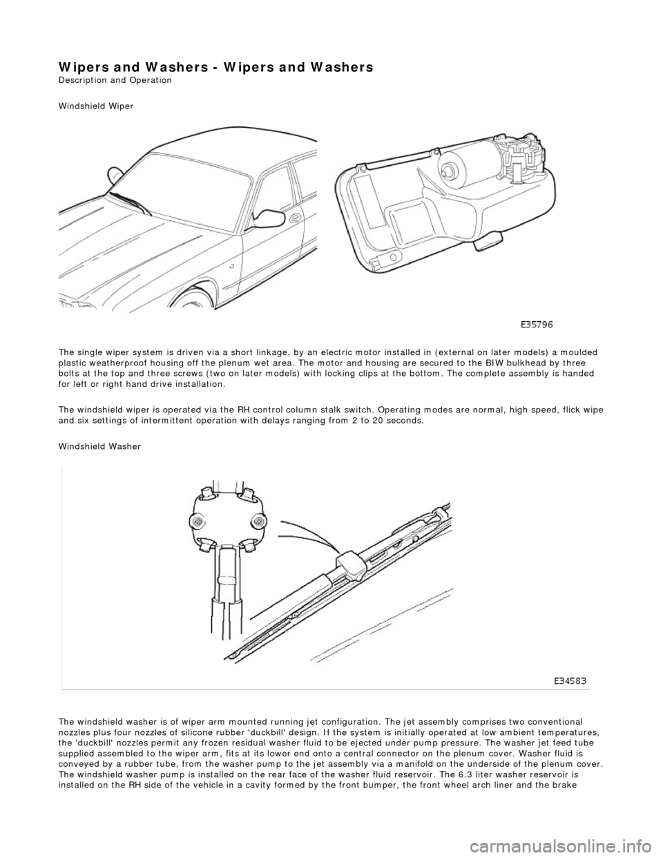
Windshield Wiper
The single wiper system is driven via a sh ort linkage, by an electric motor installed in (external on later models) a moulded
plastic weatherproof housing o ff the plenum wet area. The motor and housing are secured to the BIW bulkhead by three
bolts at the top and three screws (two on later models) with locking clips at the bottom. The complete assembly is handed
for left or right hand drive installation.
The windshield wiper is operated via the RH control column stalk switch. Operating modes are normal, high speed, flick wipe
and six settings of intermittent operation with delays ranging from 2 to 20 seconds.
Windshield Washer
The windshield washer is of wiper arm mounted running jet configuration. The je t assembly comprises two conventional
nozzles plus four nozzles of silicone rubbe r 'duckbill' design. If the system is initially operated at low ambient temperatures ,
the 'duckbill' nozzles permit an y frozen residual washer fluid to be ejected un der pump pressure. The washer jet feed tube
supplied assembled to the wiper ar m, fits at its lower end onto a central connector on the pl enum cover. Washer fluid is
conveyed by a rubber tube, from the washer pump to the jet assembly via a manifold on the underside of the plenum cover.
The windshield washer pump is installed on the rear face of the washer fluid reservoir. The 6.3 liter washer reservoir is
installed on the RH side of th e vehicle in a cavity formed by the front bu mper, the front wheel arch liner and the brake
Page 2309 of 2490
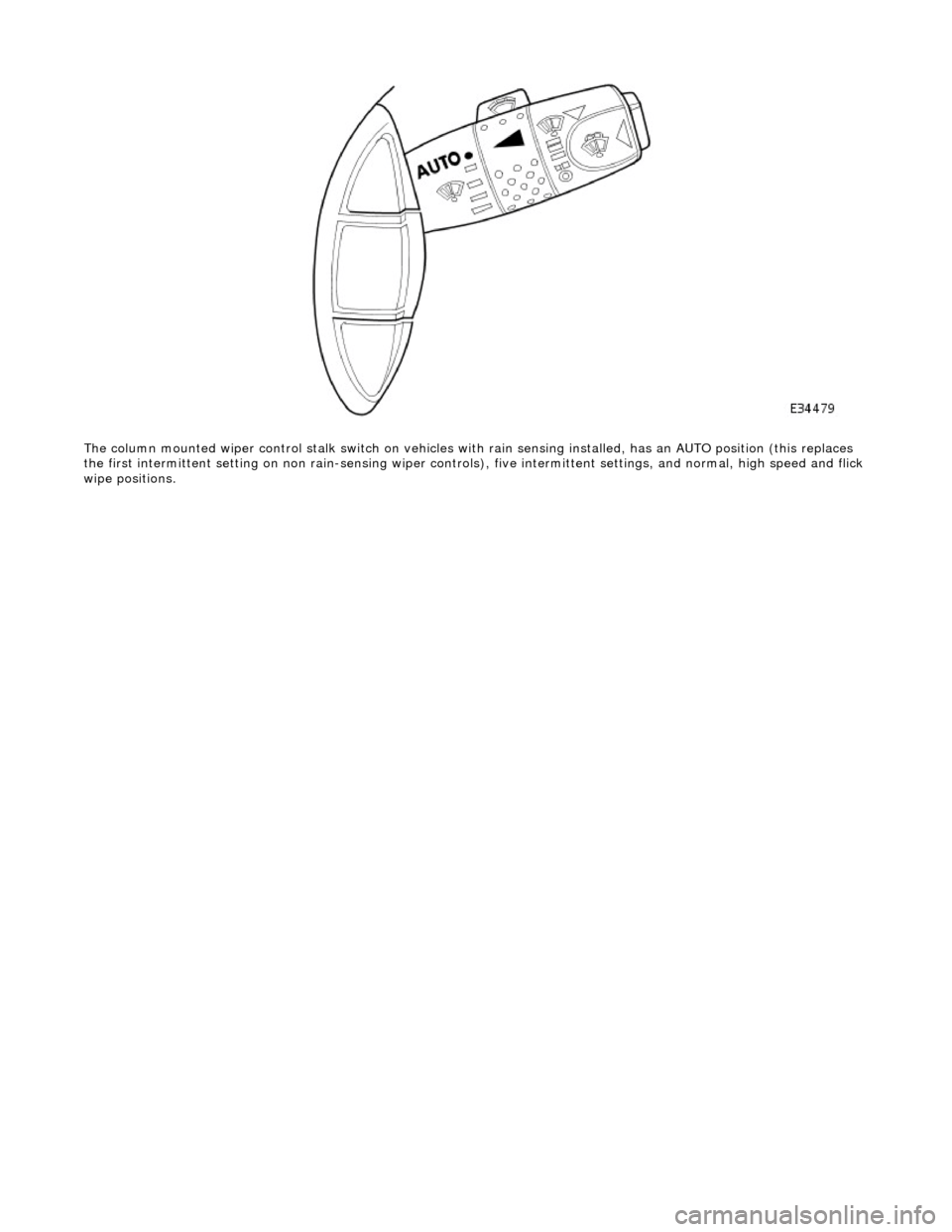
The column mounted wiper control stalk switch on vehicles with rain sensing installed, has an AUTO position (this replaces
the first intermitte nt setting on non rain-sensing wiper controls), five intermittent settings, and normal, high speed and flick
wipe positions.