abs JAGUAR X308 1998 2.G Workshop Manual
[x] Cancel search | Manufacturer: JAGUAR, Model Year: 1998, Model line: X308, Model: JAGUAR X308 1998 2.GPages: 2490, PDF Size: 69.81 MB
Page 1989 of 2490

Wiring Harnesses - Wiring Harness
Description and Operation
Introduction
CAUTION: Do not use any other heat shrink sleeve other than the approved glue lined heat shrink sleeve mentioned
in the repair procedure.
The purpose of this document is to promote quick and efficient minor repair to harness connectors or cables using approved
methods and the wiring harness repair kit. Repairs may only be made to cables and connectors which have been
mechanically, not electrically damaged. It also applies wher e the whole extent of the damage can be clearly identified and
rectified.
Care and neatness are essential requir ements in making a perfect repair.
Caution:
At the time of this first issue of the Harness Repair Guide, do not approve re pairs to any of the following circuits:
Any media orientated system transport network harnesses. Supplement restraint system (SRS) firing circuits (Air bags). Link lead assembles, which are unique to safety critical circuits such as anti-lock brake system (ABS) and
thermocouple circuits. An example of this is the ABS wheel speed sensors with moulded connectors.
4. Screened cables, leads and wiring harness(s).
If any harness(s) with defective electrical connector te rminals or wires from the above circuits are a concern,
new components must be installed.
Repair Kit
CAUTION: Where the repair procedure indica tes that a glue lined heat shrink sleeve should be applied, apply sufficient
heat to the glue lined heat shrink to melt the glue in order to provide a water tight seal. Do not over heat the glue lined
heat shrink sleeve so that the wiring harness insulation becomes damaged.
The wiring harness repair kit has been produced which comprises:
Pre-terminated wiring harness(s) of different sizes and types Three sizes of butt splice connectors A selection of colored cable identification sleeves Two sizes of glue lined heat shrink sleeves Crimping pliers A wire cutter and insulation stripper An electrical connector terminal extraction handle and tips
A suitable heat source, fo r shrinking heat shrink sleeves will be required.
The pre-insulated diamond grip range of el ectrical connector terminals and in-line, butt splice connectors contained within
the wiring harness repair kit are the only acceptable product for the repairs of wi ring harnesses. The butt connectors not
only grip the wire but also the insu lation, making a very secure joint.
If an electrical connector terminal is not included in the wiring harness repair kit then approval for the repair is NOT given
and in these circumstances a new wi ring harness must be installed.
Pre-Terminated Wiring Harness( s) and Butt Splice Connectors
All pre-terminated wiring harness(s) and butt splice connectors in the wiring harness repair kit are contained in bags which
can be resealed after use. Each bag is marked with the part number of the items stored within the bag. Each storage
compartment in the wiring harness repair kit is identified with the corresponding part number. Make sure that pre-
terminated wiring harness(s) and connectors are not mixed up it is advisable to only open one bag at a time and to reseal
Page 2012 of 2490
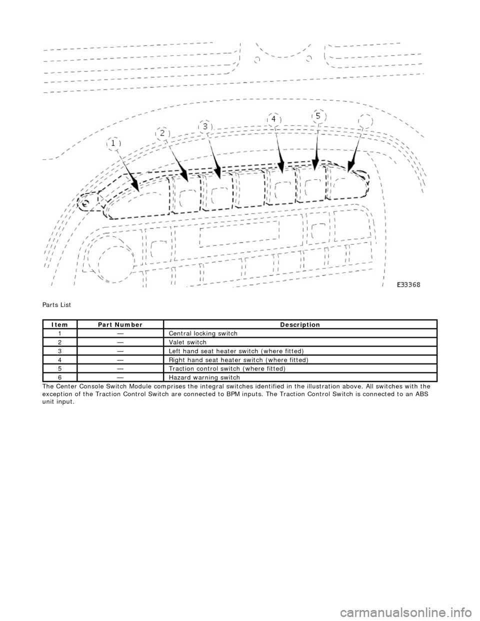
Parts List
The Center Console Switch Module comprises the integral switches identified in the illustration above. All switches with the
exception of the Traction Control Switch are connected to BPM inputs. The Traction Control Switch is connected to an ABS
unit input.
ItemPart NumberDescription
1—Central locking switch
2—Valet switch
3—Left hand seat heater switch (where fitted)
4—Right hand seat heater switch (where fitted)
5—Traction control switch (where fitted)
6—Hazard warning switch
Page 2023 of 2490
sliding roof finisher and clips. Carpet covered trims line the trunk and are secured by fir tree fasteners to the sides and fro nt inner panel.
Rear View Mirrors
The.interior rear view mirror is an electrochromic unit that automatically da rkens to prevent glare from following vehicle
lights. This automatic function is selected by pressing the switch at the bottom of the mirror. Pressing the switch again
cancels this function. An LED then illuminates when automatic dipping is operative. The light sensing unit for the Night
Sentinel automatic lamp operating system is also incorporated in the mirror casing.
The door mirrors are cheater mounted, colo r-keyed units, remote electrically adjustable and heated. Adjustment of both
mirrors is carried out from the driver's door switchpack.A slider switch selects the mirror to be adjusted, and a disc switch
adjusts the selected mirror to the required position. Mirror ad justment can only be made when the ignition switch is in
position I or II or the driver's door is open, and the selector switch is moved from the central position. The door mirrors also
automatically darken under control of the electrochromic interior rear view mirror. Mirror heating elements operate on
selection of backlight heating.
Automatic dipping of passenger door mirror for kerb view when reversing, is fitted as part of the memory pack. With the
ignition switch in position II, the mirror selector switch in the left or right position and reverse gear selected, automatic
dipping is initiated by moving the mirror toggle switch rearwards and releasing. On receipt of the dip signal, the passenger
door mirror is driven downwards either 7 degrees, bottom of travel, or 4,5 to 5,5 seconds, whichever occurs first.
Subsequent rearward movement of the toggle switch achieves further dipping of the mirror in the same increments and
sequence. The mirror can be manu ally returned to the normal memorised positi on by moving the toggle switch forward with
reverse gear selected. The mirror will auto matically return to memorised position on deselection of reverse gear, or moving
ignition switch from position II.
Door mirror fold-back where fitted, to facilitate parking in conf ined spaces, can be initiated when the ignition switch is in
position I or II, the mirror selector switch is in the centra l position and vehicle speed is below 19 km/h (12 mph). Mirror
fold-back is then initiated by moving the toggle switch rear wards and releasing it. The door mirrors are returned to the
normal driving position by agai n moving toggle switch rearwards. There is no speed constraint on this operation. In the
event of a fold-back mirror becoming 'out of position' due to acci dental impact, it must only be re-positioned by initiating
the fold-back sequence.
Loss of power supplies will result in loss of mirror fold-back memory. In the event of such a memory loss with mirrors in the
normal position, fold-back will operate on second movement of the toggle swit ch. On loss of memory with mirrors in the
fold-back position, they will return to the no rmal position on next fold-back operation.
Bumpers
Each bumper comprises a beam mounted to the body via two strut assemblies, and a moulded polypropylene cover
incorporating side armatures and chrome plated blades. Each strut is secured to the BIW by three bolts and supports the
beam on a single bolt/height adjuster. The front bumper cover which is moulded to form a lo wer air intake for the cooling
pack, also incorporates left and right handed twin fog lamps, brake coolin g ducts. Side marker lamps fitted for some
markets serve only as reflectors for UK and Europe. A plastic undertray secured to the lower edge of the front bumper,
improves airflow and minimises the ingres s of road grime in that area. Standard bumpers have glass mat thermoplastic
(GMT) beams mounted on GMT struts. For certain markets, aluminium bumper beams are installed on menasco energy
absorbing struts. Whilst both types of front bumper provide a fu lly integrated 'soft front end' that satisfies bumper impact
requirements, the energy absorbing front and rear bumpers are further designed to withstand 5mph (8kph) impacts with no
visible damage sustained. Side markers/re flectors, and direction indicators are designed for ease of ac cess from the outside
of the bumper. For adjustment and bulb change, the fog lamps are accessed from th e bumper interior. The bumper covers
are body coloured and matched. Replacement covers are supplied complete with side armatures and are finished in primer
Trunk
The trunk houses the spare wheel, the battery, an electrical carrier containing electrical fuses, relays and modules and a
compact disc auto-changer attached to body bracketry. The trun k is fitted with push-fit liners to the sides and front inner
panel.The carpet covered floor is in two removable sections, one covering the spare wheel and wheel changing equipment,
the other covering the battery and electrical carrier. The front and rear edges of the floor board loca te in blocks on the fuel
tank backboard and the rear of the body , which provide two height settings to accommodate the difference in thickness
between the space saver and full sized spare wheels. A moulded finisher covering the rear of the trunk below the sill is
secured to the rear panel by tabs and fir tree fasteners. Finisher panels fitted over the rear lamp units provide for access
from the trunk. Finisher panels fitted to the rear lamp units provide trunk inte rior access to the lamps. The trunk lid
underside is fitted with a removable mo ulded liner and two trunk illumination light s. Trunk locking is based on a central
latch and striker, operated electrically through the central lo cking system by an adjacent actuator or by key in a barrel lock
Page 2040 of 2490
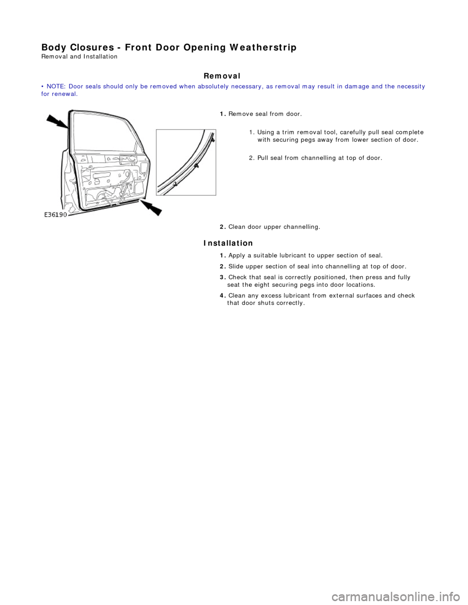
Body Closures - Front Door Opening Weatherstrip
Removal and Installation
Removal
• NOTE: Door seals should only be remove d when absolutely necessary, as removal may result in damage and the necessity for renewal.
Installation
1. Remove seal from door.
1. Using a trim removal tool, carefully pull seal complete
with securing pegs away from lower section of door.
2. Pull seal from chan nelling at top of door.
2. Clean door uppe r channelling.
1. Apply a suitable lubricant to upper section of seal.
2. Slide upper section of seal into channelling at top of door.
3. Check that seal is correctly positioned, then press and fully
seat the eight securing pegs into door locations.
4. Clean any excess lubricant from external surfaces and check
that door shuts correctly.
Page 2053 of 2490
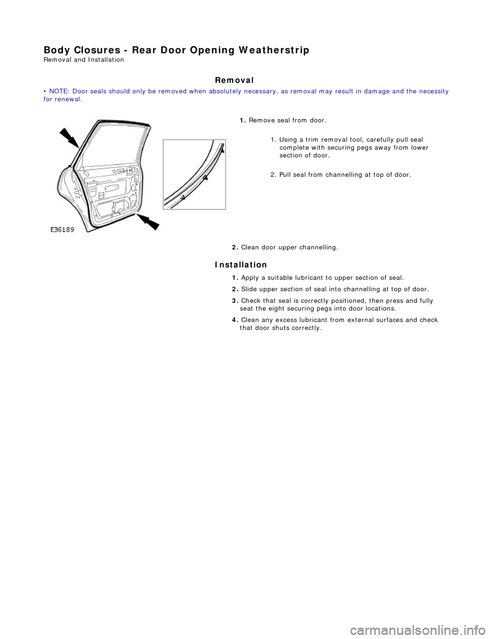
Body Closures - Rear Door Opening Weatherstrip
Removal and Installation
Removal
• NOTE: Door seals should only be removed when absolutely necessary, as removal may result in damage and the necessity for renewal.
Installation
1. Remove seal from door.
1. Using a trim removal tool, carefully pull seal complete with securing pegs away from lower
section of door.
2. Pull seal from chan nelling at top of door.
2. Clean door uppe r channelling.
1. Apply a suitable lubricant to upper section of seal.
2. Slide upper section of seal into channelling at top of door.
3. Check that seal is correctly positioned, then press and fully
seat the eight securing pegs into door locations.
4. Clean any excess lubricant from external surfaces and check
that door shuts correctly.
Page 2054 of 2490
Interior Trim and Ornamentation - Interior Trim
Description and Operation
Carpets
The passenger compartment carpet is a one piece moulded constr uction with integral sound deadening material, heel mats
and driver's footrest. The carpet is attach ed to the vehicle floor by plastic clips fitted below the door treadplates. Removal of the carpet necessitates re moval of the front seats, lifting of the centre console rear extens ion and removal of the heelboard
carpet.
Fascia
The full width, slush moulded, soft feel PVC fascia is mounted on an injection moulded armature and is faced with wood
veneer. In addition to the air conditioning and central, outer and demisting vents, it accepts instrument packs dedicated to
market requirements and a centrally mounted analogue clock.
Doors
The one-piece door casings are trimmed in UEV to match the seating, with wood veneer at the waistline and a carpet insert
at the front lower corner. Each casing is secured to the door inner panel by fir tree press fast eners along the lower section,
two armrest fixings at the centre and vene er panel dowels and fixings at the top. The armrests which are common to front
and rear doors, are trimmed in matching leather or UEV according to specification. The door switchpacks, dedicated to
driver and front or rear passenger, are in corporated in the armrests. A speaker is in stalled in the lower section of each door
and a tweeter is incorporated behind each interior door handle escutcheon. Where premium ICE is fitted, the front tweeters
are installed in the upper A posts.
A, B, C and D Posts
On each side,a grained UEV finisher trimmed to match the headlining is secured to the 'A' post and cantrail by fir tree
fasteners locating in BIW apertures. The upper 'D' post finisher is trimmed and secured in the same manner. The single
piece'B/C' post finishers, also finished in grained matching UEV, each have a front se at belt exit aperture and are secured to
the BIW by four spring clips and two fir tree fasteners.
Headlining
The one-piece headlining consists of a 6mm thick polyurethane foam membrane covered with suede effect knitted polyester. The headlining is secured to the BIW roof by body tangs, the roof console, sun visors, combined grab handles and coat
hooks, the cantrail finishers and where fitt ed, the sliding roof finisher and clips.
Trunk
Carpet covered trims line the trunk and are secured by fir tr ee fasteners to the sides and front inner panel. The carpet
covered, two-section, removable trunk fl oor provides access to the spare wheel and wheel changing equipment, the battery
and electrical carrier. The floor board rests on the spare wheel, with the front and rear edges locating in blocks on the fuel
tank backboard and the rear of the body. The support blocks provide for two floor he ight settings to accommodate either a
space saver or full size spare wheel.A moulded finisher covering the rear of the trunk below the sill is secured to the rear
panel by tabs and fir tree fasteners. Finish er panels fitted to the rear lamp units provide trunk interior access to the lamps.
The trunk lid underside is fitted with a removabl e moulded liner and two trunk illumination lights.
Page 2271 of 2490
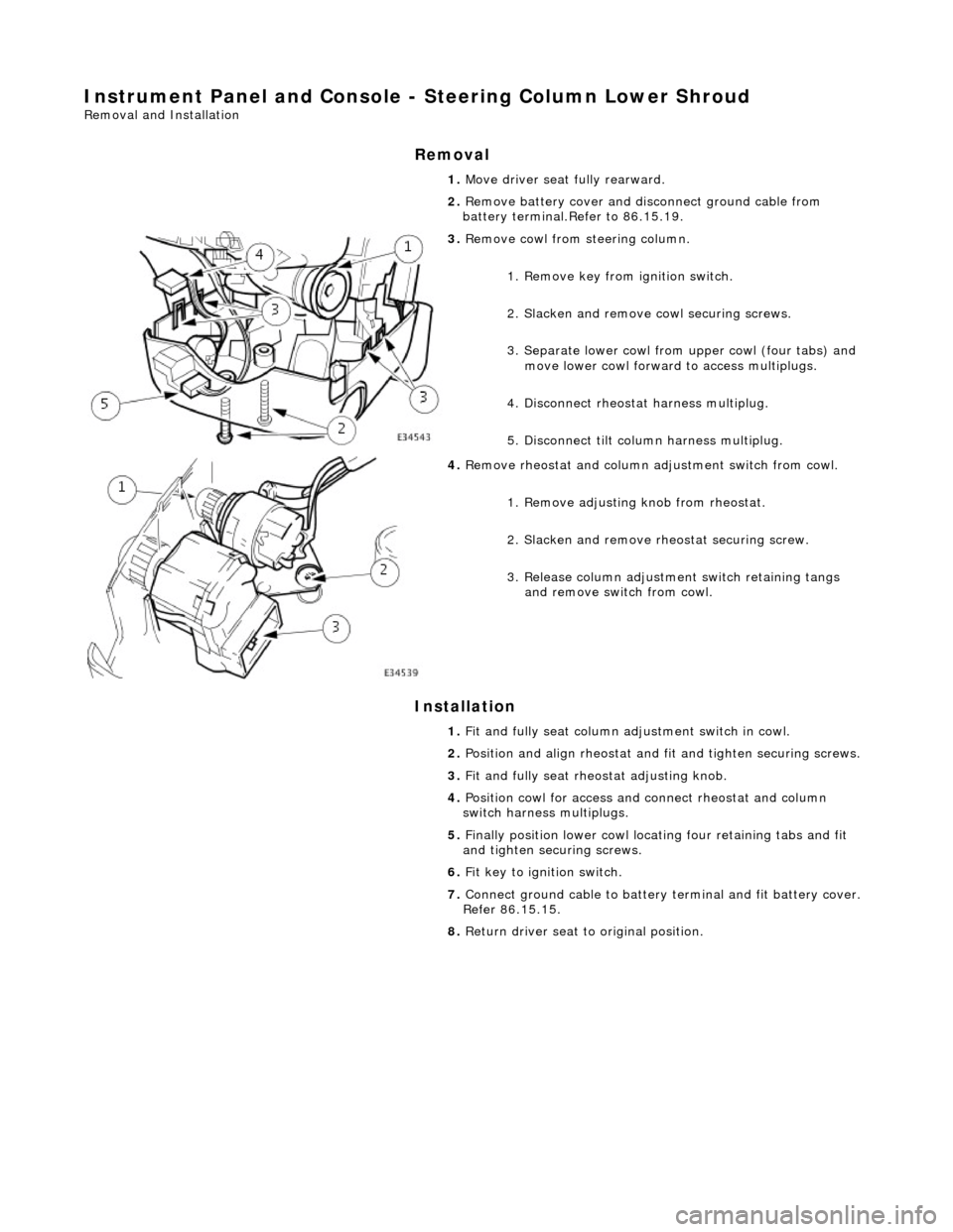
Instrument Panel and Console - Steering Column Lower Shroud
Removal and Installation
Removal
Installation
1.
Move driver seat fully rearward.
2. Remove battery cover and disconnect ground cable from
battery terminal.Refer to 86.15.19.
3. Remove cowl from steering column.
1. Remove key from ignition switch.
2. Slacken and remove cowl securing screws.
3. Separate lower cowl from upper cowl (four tabs) and move lower cowl forward to access multiplugs.
4. Disconnect rheostat harness multiplug.
5. Disconnect tilt column harness multiplug.
4. Remove rheostat and column adjustment switch from cowl.
1. Remove adjusting knob from rheostat.
2. Slacken and remove rh eostat securing screw.
3. Release column adjustment switch retaining tangs and remove switch from cowl.
1. Fit and fully seat column ad justment switch in cowl.
2. Position and align rheostat and fit and tighten securing screws.
3. Fit and fully seat rheo stat adjusting knob.
4. Position cowl for access and connect rheostat and column
switch harness multiplugs.
5. Finally position lower cowl locating four retaining tabs and fit
and tighten securing screws.
6. Fit key to ignition switch.
7. Connect ground cable to battery terminal and fit battery cover.
Refer 86.15.15.
8. Return driver seat to original position.
Page 2272 of 2490
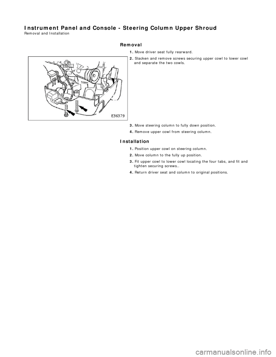
Instrument Panel and Console - Steering Column Upper Shroud
Removal and Installation
Removal
Installation
1.
Move driver seat fully rearward.
2. Slacken and remove screws securing upper cowl to lower cowl
and separate the two cowls.
3. Move steering column to fully down position.
4. Remove upper cowl fr om steering column.
1. Position upper cowl on steering column.
2. Move column to the fully up position.
3. Fit upper cowl to lower cowl locating the four tabs, and fit and
tighten securing screws..
4. Return driver seat and column to original positions.
Page 2343 of 2490

Bumpers -
Torques
ComponentNm
Bolts securing bumper beam to strut39 - 51
Bolts securing bumper guide to body15,5 - 20,5
Bolts securing energy absorbing strut to body22 - 28
Bolts securing non-energy absorbing strut to body15,5 - 20,5
Page 2384 of 2490
Generally, resistance spot welding equipment used in the motor vehicle repair industry does not produce welds of equivalent strength to those achieved during manufactu re. The expression 'single row of resistance spot welds' indicates that the spots
should be spaced on a pitch of 19mm to 25mm, which normally results in mo re spot welds than those produced in the
original factory joint.
Resistance spot welds should be removed using a resistance spot weld cutter. If the new joint is to be MIG plug welded, old
resistance spot welds should be cut from the panel to be reta ined and the resulting holes used for plug welding. Suitable
holes may also be drilled or punched; 8,0 mm dia for sect ions up to 1,6 mm, and 10,0 mm dia for thicker sections.
PLASTICS-EXPLANATORY NOTES
Plastic component and trim materials
This table, in conjunction with the illu strations on the following pages will enable rapid identification of the particular
material of any major plastic part.
• NOTE: Only those components suitable for economic reclamation are identified.
Plastics - Handling Notes
The exterior panel temperature of a vehicle must not exceed 95°C at any time and may only be held at this level for a
maximum of two hours. Similarly, interior vehicle temperatur e must be limited to 86°C for a maximum duration of two
hours. Exposure to temperatures above those specified may result in distorted or permanently damaged components. If
there is doubt concerning temperature limitations, components that may be adversel y affected by exposure to heat should
be removed from the vehicle.
Plastic components that become greasy may be clea ned with an 'SBP 3' spirit wipe, or equivalent.
Recycled Materials
Any of the materials listed in this section, may be recycled provided that they ar e not contaminated by other incompatible
plastics or metals. For instan ce, the air conditioning unit case, manufactur ed from PP (polypropylene), must be separated
from the heater matrix, evaporator, contro l devices (electronic and mechanical) and all fixings before it can be considered
for recycling. After removal, the case mu st only be placed for disposal with materials of the same generic type. Bumper
cover assemblies similarly have side arma tures of dissimilar materials rivetted to them, these together with their fixings
must be removed prior to recy cling. Components manufactured from 'blended' materials must not be recycled with pure
materials. For example do not mix PC/ABS (wheel trim) with ABS ('B' pillar upper trim).
Plastics, Component Location and Type - External
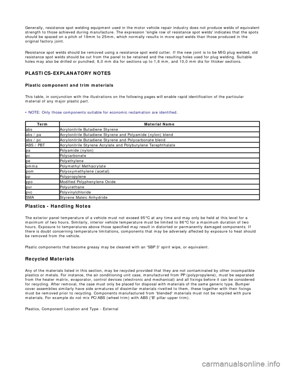
TermMaterial Name
absAcrylonitrile Butadiene Styrene
abs / paAcrylonitrile Butadiene Styrene and Polyamide (nylon) blend
abs / pcAcrylonitrile Butadiene Styrene and Polycarbonate blend
ABS / PBTAcrylonitrile Styrene Acrylate and Polybutylene Terephthalate
paPolyamide (nylon)
pcPolycarbonate
pePolyethylene
pmmaPolymethyl Methacrylate
pomPolyoxymethylene (acetal)
ppPolypropylene
ppoModified Polyphenylene Oxide
purPolyurethane
pvcPolyvinylchloride
SMAStyrene Maleic Anhydride