abs JAGUAR X308 1998 2.G Manual PDF
[x] Cancel search | Manufacturer: JAGUAR, Model Year: 1998, Model line: X308, Model: JAGUAR X308 1998 2.GPages: 2490, PDF Size: 69.81 MB
Page 450 of 2490

Anti-Lock Control - Wheel Speed Se
nsor Ring
Re
mo
val and Installation
Remov
a
l
CAUTI
O
N: Replacement of
nuts and bolts: Various thread-locking devices are used on nuts and bolts throughout the
vehicle. These devices restrict the number of times a nut or bolt can be used. See section 100-00 for information.
S p
ecial Tool(s)
Hub Holdin
g Tool
2
04-195 (JD 227)
ABS Rotor Nut Socket
2
06-
066A
1.
Op
en engine compartment and
fit paintwork protectors to
fenders.
2. Raise front of vehicle and support on stands. Refer to section
100-02.
3. Remove front wheel. Re fer to section 204-04.
4. Remove front brake disc. Refer to operation 70.10.12.
5. Remove vertical link and hub assembly. Refer to operation
60.25.38.90.
6. Re
move brake-disc shield from vertical link.
1. Remove screws.
2. Remove disc shield.
7. Using special tool, secure vertical link and hub assembly in a
vice.
Secure special tool
in a vice.
Posit
i
on hub in tool.
Fit and
tighten wheel nuts.
Page 479 of 2490
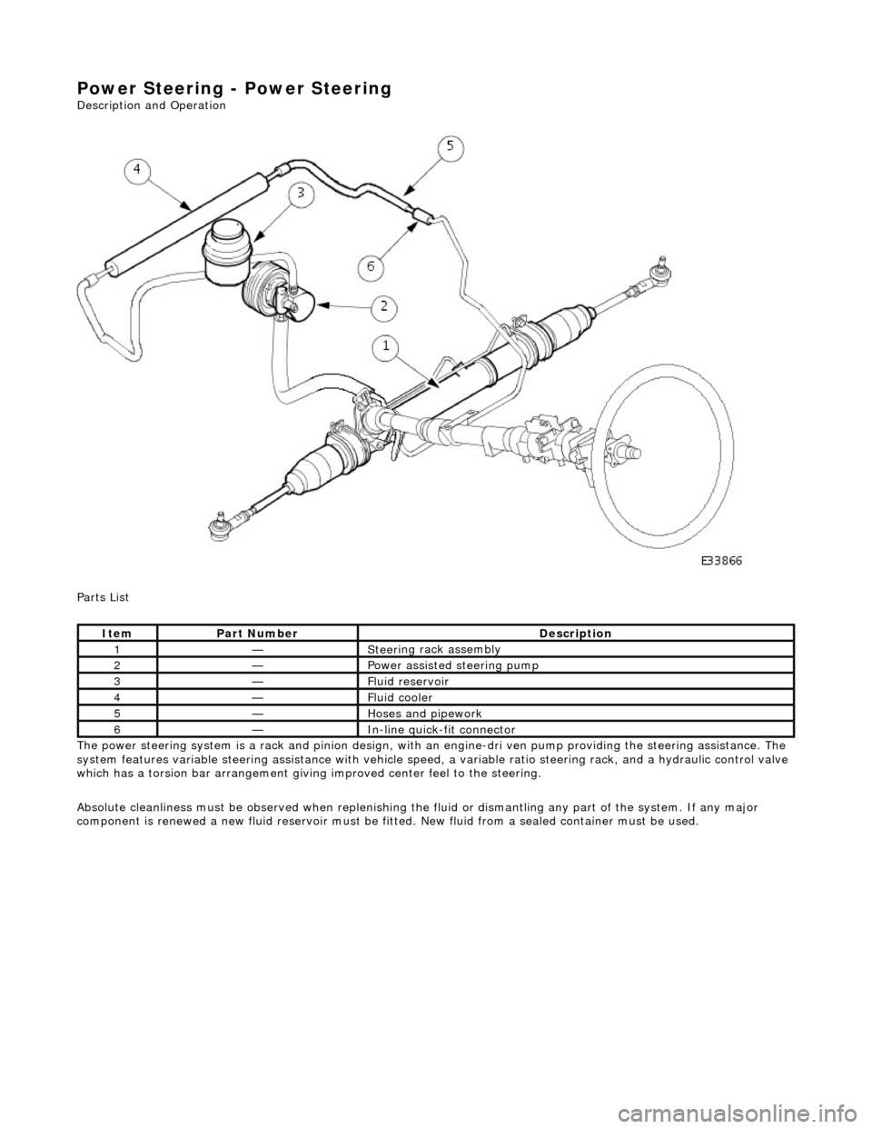
Power Steering - Power Steering
Description an
d Operation
Parts List
The power steering system is a rack and pinion design, with an engine-dri ve n pump providing the steering assistance. The
system features variable steering assistance with vehicle spee d, a variable ratio steering rack, and a hydraulic control valve
which has a torsion bar arrangement giving improved center feel to the steering.
Absolute cleanliness must be observed wh en replenishing the fluid or dismantling any part of the system. If any major
component is renewed a new fluid rese rvoir must be fitted. New fluid from a sealed container must be used.
It
em
Par
t Number
De
scription
1—Steeri
ng rack assembly
2—Power as
sisted steering pump
3—F
luid reservoir
4—F
luid cooler
5—Hoses and pipework
6—In-
line quick-fit connector
Page 527 of 2490
E
ngine Management System Components
Electronic Throt
tle
The
electronic throttle assembly, in resp
onse to signals from both the driver and the ECM, adjusts idle speed, sets the
throttle valve to the position requested by the driver's accelerator / throttle pedal, cruise and traction control, power
limitation and catalyst warm-up.
Mass
Air Flow Meter
The sensor i
s located in the air flow mete
r assembly and outputs an analogue voltag e to the ECM. This sensor measures air
flow into the engine inlet system and is calibrated to measure kg / hour.
In
take Air Temperature
Th
e intake air temperature sensor is loca
ted in the air flow meter assembly and outputs an analogue voltage to the ECM.
The ECM will substitute a default value eq ual to 50°C should this sensor fail.
Fuel Injectors
The eigh
t bottom fed fuel injectors are located in the fuel rails. Th
e fuel injectors are electromagnetic solenoid valves
controlled by the ECM. The pulse time for the injector combined with the fuel pr essure determines the volume of fuel
injected to the manifold.
Fue
l Delivery
The fu
el pump provides fuel to the fuel rail where the circulat
ing pressure is controlled by a pressure regulator valve; excess
fuel is returned to the fuel tank.
The pressure regulator valve is controlled by manifold depression so that fuel delivery pressure is maintained at
approximately 3 bar above manifold pressure.
Fuel Pump
Relay
The ECM controls thi
s component for normal
engine running. The security system may disable this relay via communication
with the ECM.
Fuel Lev
el Sensing
The tank fuel
is measured by the fuel le
vel sensor . This signal is used by the ECM as an in put to certain diagnostics.
Eva
porative Valve
Excess vapour
formed in the fuel tank is
absorbed into the evaporative emission pu rge control canister. While the engine is
running, the fuel absorbed in the canister is gradually purged back into the engine. The rate of purging is governed by
engine operating conditions and vapour concentration level. Operating conditions which affect the purge rate are:
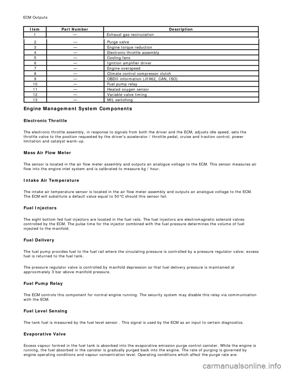
2—Purge
valve
3—Engine
torque reduction
4—E
lectronic throttle assembly
5—Coo
ling fans
6—Ignition amplifier driver
7—Engine overspeed
8—Cli
mate control compressor clutch
9—O
BDII information (J1962, CAN, ISO)
10—F
uel pump relay
11—Heat
ed oxygen sensor
12—Vari
able valve timing
13—MIL sw
itching
ECM Out
puts
It
em
Par
t Number
De
scription
1—Exhaus
t gas recirculation
Page 616 of 2490
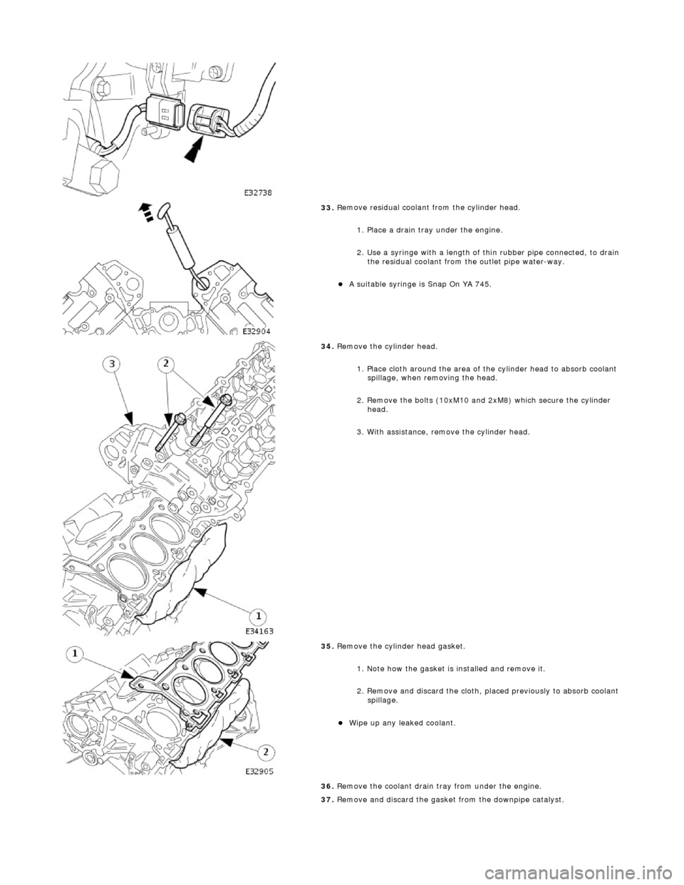
33. R
emove residual coolant from the cylinder head.
1. Place a drain tray under the engine.
2. Use a syringe with a length of thin rubber pipe connected, to drain the residual coolant from the outlet pipe water-way.
A s u
itable syringe is Snap On YA 745.
34 . R
emove the cylinder head.
1. Place cloth around the area of th e cylinder head to absorb coolant
spillage, when removing the head.
2. Remove the bolts (10xM10 and 2xM8) which secure the cylinder head.
3. With assistance, remove the cylinder head.
35 . R
emove the cylinder head gasket.
1. Note how the gasket is installed and remove it.
2. Remove and discard the cloth, placed previously to absorb coolant spillage.
Wipe up any l e
aked coolant.
36. Remove the coolant drain tray from under the engine.
37. Remove and discard the gasket from the downpipe catalyst.
Page 631 of 2490
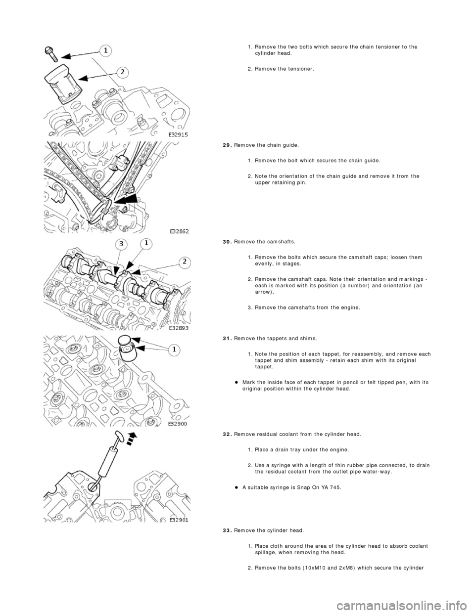
1.
Remove the two bolts which secure the chain tensioner to the
cylinder head.
2. Remove the tensioner.
29
.
Remove the chain guide.
1. Remove the bolt which secures the chain guide.
2. Note the orientation of the chain guide and remove it from the upper retaining pin.
30
.
Remove the camshafts.
1. Remove the bolts which secure the camshaft caps; loosen them evenly, in stages.
2. Remove the camshaft caps. Note their orientation and markings -
each is marked with its position (a number) and orientation (an
arrow).
3. Remove the camshafts from the engine.
31
.
Remove the tappets and shims.
1. Note the position of each tappet, for reassembly, and remove each
tappet and shim assembly - retain each shim with its original
tappet.
Mark
the inside face of each tappet in pencil or felt tipped pen, with its
original position within the cylinder head.
32
.
Remove residual coolant from the cylinder head.
1. Place a drain tray under the engine.
2. Use a syringe with a length of thin rubber pipe connected, to drain the residual coolant from the outlet pipe water-way.
A s
uitable syringe is Snap On YA 745.
33. Remove the cylinder head.
1. Place cloth around the area of th e cylinder head to absorb coolant
spillage, when removing the head.
2. Remove the bolts (10xM10 and 2xM8) which secure the cylinder
Page 632 of 2490

Installation
hea
d.
3. With assistance, remove the cylinder head.
34 . R
emove the cylinder head gasket.
1. Note how the gasket is installed and remove it.
2. Remove and discard the cloth, placed previously to absorb coolant spillage.
Wipe up any l e
aked coolant.
35. Remove the coolant drain tray from under the engine.
36. Remove and discard the gasket from the downpipe catalyst.
Cle
an the gasket faces of the catalyst and the exhaust manifold.
37. Clean cylinder head and cylinder block gasket faces.
Ensu
re that all threaded holes in the cylinder block face are clean and
free from oil.
Cl ean and
inspect the cylinder head bolts. They may be re-used on two
occasions. When re- used, each bolt head should be marked with one
dot from an automatic centre punch.
38. Clean and inspect all relevant components and mating faces.
1. CAUTIONS: If a replacement cylinder head is to be installed to a vehicle with VCT
the cylinder head must have the oil gallery blind rivet removed before
installation.
Make sure that all debris is removed from the cylinder head and cylinder
head oil gallery.
Vehicles fitted with VCT: Remove the blind rivet from the VCT oil gallary. • NOTE: The centre bore of the blind rivet is 6 mm diameter.
Page 963 of 2490

Engine Cooling - Coolant Expansi
on Tank
Re
moval and Installation
Remov
al
1.
O
pen the engine compartment and fit paintwork protection
sheets.
2. R
emove the centre trim panel
from the engine compartment.
1. Remove the left hand side enclosure panel.
2. Remove the centre trim panel.
3. Ensure that the cooling system is cool and very carefully,
remove the pressure cap.
4. Place a cloth under the expansion tank to absorb any spillage
caused by disconnecting the hoses.
5. R
elease the hoses (Quick Fit connections) from the expansion
tank.
1. Release the hose, expansion tank to thermostat housing (coolant outlet pipe on supercharged
engines).
2. Release the hose, expansion tank to recovery tank.
3. Release the hose, expansion tank to radiator..
6. Fit blanking plugs to the pipes and the tank.
7. Re
move the expansion tank from the mounting.
1. Disconnect the coolant level sensor connector.
2. Remove the nuts which secures the tank.
8. Remove the expansion tank from the vehicle.
1. Use a pipe clamp to clam p the bottom hose branch.
2. Release the pipe clip an d move it along the pipe.
3. Disconnect the tank from the bottom hose and
Page 1120 of 2490
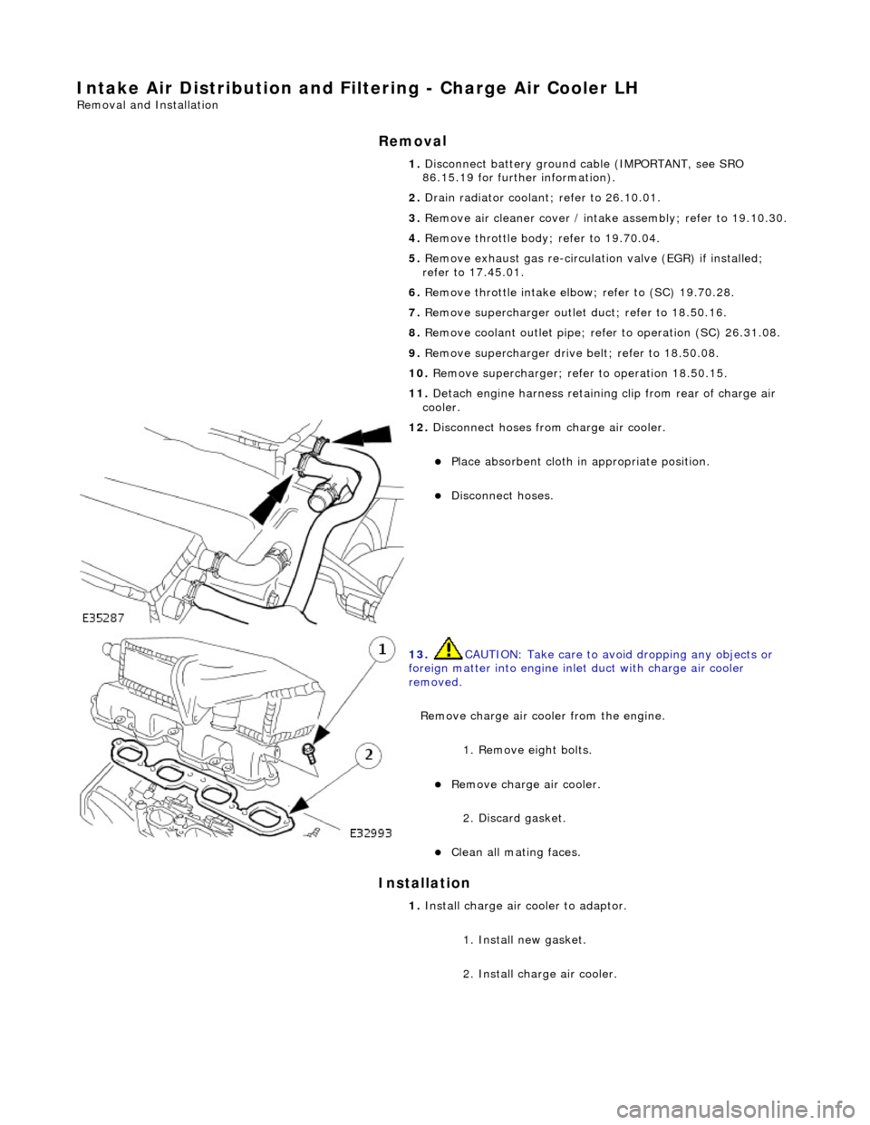
Intake Air Distribution and Filtering - Charge Air Cooler LH
Remo
val and Installation
Remov
a
l
Installation
1. Disc onne
ct battery ground cable (IMPORTANT, see SRO
86.15.19 for further information).
2. Drain radiator coolant; refer to 26.10.01.
3. Remove air cleaner cover / intake assembly; refer to 19.10.30.
4. Remove throttle body; refer to 19.70.04.
5. Remove exhaust gas re-circulation valve (EGR) if installed;
refer to 17.45.01.
6. Remove throttle intake elbo w; refer to (SC) 19.70.28.
7. Remove supercharger outlet duct; refer to 18.50.16.
8. Remove coolant outlet pipe; refe r to operation (SC) 26.31.08.
9. Remove supercharger drive belt; refer to 18.50.08.
10. Remove supercharger; refer to operation 18.50.15.
11. Detach engine harness retaining clip from rear of charge air
cooler.
12. Di
sconnect hoses from charge air cooler.
Pla
ce absorbent cloth in appropriate position.
Di
sc
onnect hoses.
13 .
CAUTI
ON: Take care to avoi
d dropping any objects or
foreign matter into engine inle t duct with charge air cooler
removed.
Remove charge air cooler from the engine.
1. Remove eight bolts.
Remove charge air cooler.
2
. Discard gasket.
Cle
a
n all mating faces.
1.
Install ch
arge air
cooler to adaptor.
1. Install new gasket.
2. Install charge air cooler.
Page 1122 of 2490
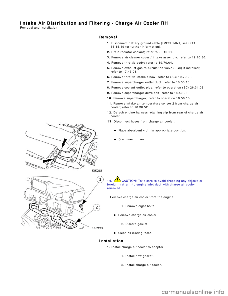
Intake Air Distribution and Filtering - Charge Air Cooler RH
Remo
val and Installation
Remov
a
l
Installation
1. Disc onne
ct battery ground cable (IMPORTANT, see SRO
86.15.19 for further information).
2. Drain radiator coolant; refer to 26.10.01.
3. Remove air cleaner cover / intake assembly; refer to 19.10.30.
4. Remove throttle body; refer to 19.70.04.
5. Remove exhaust gas re-circulation valve (EGR) if installed;
refer to 17.45.01.
6. Remove throttle intake elbo w; refer to (SC) 19.70.28.
7. Remove supercharger outlet duct; refer to 18.50.16.
8. Remove coolant outlet pipe; refe r to operation (SC) 26.31.08.
9. Remove supercharger drive belt; refer to 18.50.08.
10. Remove supercharger; refer to operation 18.50.15.
11. Remove intake air temperatur e sensor 2 from charge air
cooler; refer to 18.30.52.
12. Detach engine harness retaining clip from rear of charge air
cooler.
13. Di
sconnect hoses from charge air cooler.
Pla
ce absorbent cloth in appropriate position.
Di
sc
onnect hoses.
14 . CAUTI
ON: Take care to avoi
d dropping any objects or
foreign matter into engine inle t duct with charge air cooler
removed.
Remove charge air cooler from the engine. 1. Remove eight bolts.
Remove charge air cooler.
2
. Discard gasket.
Cle
a
n all mating faces.
1.
Install ch arge air
cooler to adaptor.
1. Install new gasket.
2. Install charge air cooler.
Page 1130 of 2490
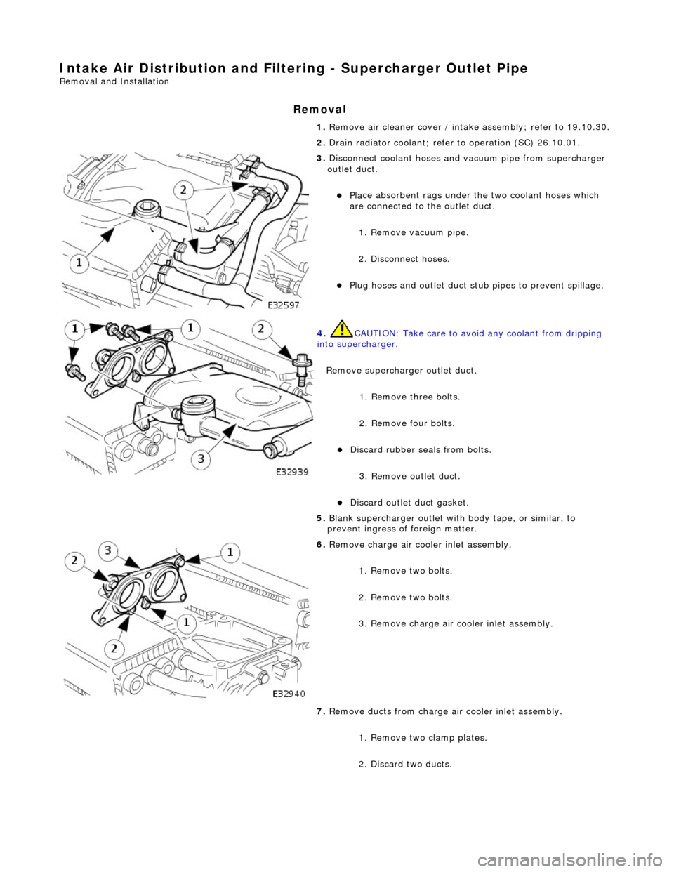
Intake Air Distribution and Filtering - Supercharger Outlet Pipe
Remo
val and Installation
Remov
a
l
1.
Re
move air cleaner cover / intake
assembly; refer to 19.10.30.
2. Drain radiator coolant; refer to operation (SC) 26.10.01.
3. Disc
onnect coolant hoses and vacuum pipe from supercharger
outlet duct.
Pl a
ce absorbent rags under
the two coolant hoses which
are connected to the outlet duct.
1. Remove vacuum pipe.
2. Disconnect hoses.
Plu g
hoses and outlet duct stub pipes to prevent spillage.
4. CAUTIO
N: Take care to avoi
d any coolant from dripping
into supercharger.
Remove supercharger outlet duct. 1. Remove three bolts.
2. Remove four bolts.
Di
scard rubber seals from bolts.
3. Remove outlet duct.
Discard ou
tlet duct gasket.
5.
Bla
nk supercharger outlet with
body tape, or similar, to
prevent ingress of foreign matter.
6. Remove charge air c oo
ler inlet assembly.
1. Remove two bolts.
2. Remove two bolts.
3. Remove charge air cooler inlet assembly.
7. Remove ducts from charge air cooler inlet assembly.
1. Remove two clamp plates.
2. Discard two ducts.