JAGUAR X308 1998 2.G Workshop Manual
X308 1998 2.G
JAGUAR
JAGUAR
https://www.carmanualsonline.info/img/21/7640/w960_7640-0.png
JAGUAR X308 1998 2.G Workshop Manual
Page 1978 of 2490
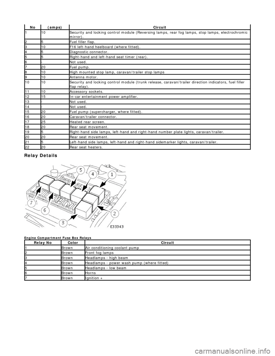
Relay Details
Engine Compartment Fuse Box Relays
No(amps)Circuit
110Security and locking control module (Reversing lamps, rear fog lamps, stop lamps, electrochromic
mirror).
25Fuel filler flap.
310F16 left-hand heelboard (where fitted).
45Diagnostic connector.
55Right-hand and left-han d seat timer (rear).
6-Not used.
720Fuel pump.
810High mounted stop lamp, caravan/trailer stop lamps
910Antenna motor.
1010Security and locking control module (trunk release, caravan/trailer direction indicators, fuel filler
flap relay).
1110Accessory sockets.
1215In-car entertainment power amplifier.
13-Not used.
14-Not used.
1520Fuel pump (supercharger, where fitted).
1620Caravan/trailer connector.
1725Heated rear screen.
1820Rear seat movement.
195Right-hand side lamps, left-h and and right-hand number pl ate lights, caravan/trailer.
2020Rear seat movement.
215Left-hand side lamps, left-hand and right-hand sidemarker lights, caravan/trailer.
2220Rear seat heaters.
Relay NoColorCircuit
1BrownAir conditioning coolant pump
2BrownFront fog lamps
3BrownHeadlamps - high beam
4BrownHeadlamps - power wash pump (where fitted)
5BrownHeadlamps - low beam
6BrownHorns
7BrownIgnition +
Page 1979 of 2490
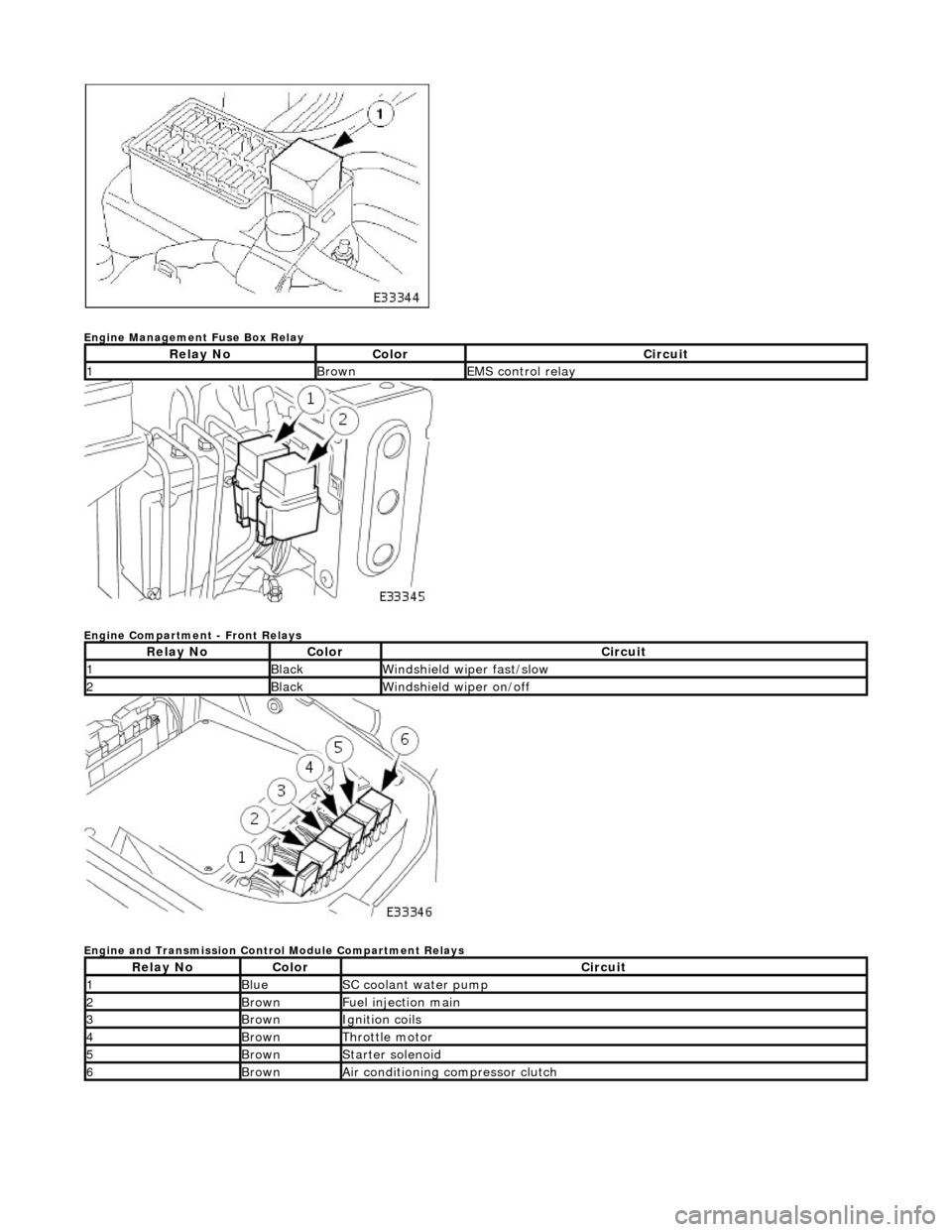
Engine Management Fuse Box Relay
Engine Compartment - Front Relays
Engine and Transmission Control Module Compartment Relays
Relay NoColorCircuit
1BrownEMS control relay
Relay NoColorCircuit
1BlackWindshield wiper fast/slow
2BlackWindshield wiper on/off
Relay NoColorCircuit
1BlueSC coolant water pump
2BrownFuel injection main
3BrownIgnition coils
4BrownThrottle motor
5BrownStarter solenoid
6BrownAir conditioning compressor clutch
Page 1980 of 2490
Front Firewall Relays
Heelboard Fuse Box Relays - Right hand side
* not illustrated
Heelboard Fuse Box Relays - Left hand side
Relay NoColorCircuit
1BlackWindshield RH heater (where fitted)
2BlackWindshield LH heater (where fitted)
Relay NoColorCircuit
1BlueDoor mirror heater
2BlueAir conditioning RH blower
3BlueLeft rear seat lumbar deflate (where fitted) *
4BrownAuxiliary +
5BlueAir conditioning LH blower
Relay NoColorCircuit
1BrownIgnition +
2VioletDoor mirror fold flat (where fitted)
3VioletAir conditioning isolate
4VioletDoor locks
Page 1981 of 2490
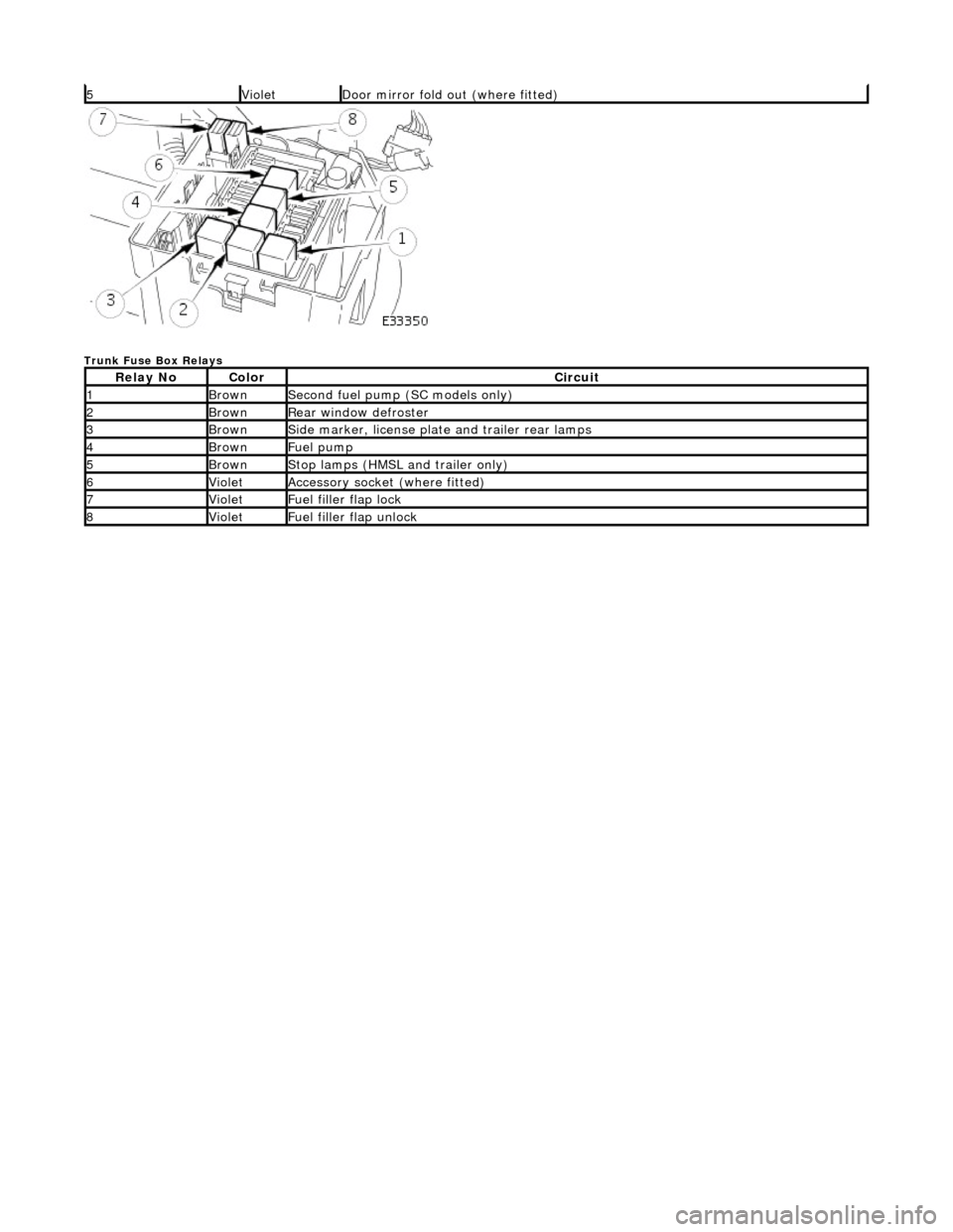
Trunk Fuse Box Relays
5VioletDoor mirror fold out (where fitted)
Relay NoColorCircuit
1BrownSecond fuel pump (SC models only)
2BrownRear window defroster
3BrownSide marker, license plate and trailer rear lamps
4BrownFuel pump
5BrownStop lamps (HMSL and trailer only)
6VioletAccessory socket (where fitted)
7VioletFuel filler flap lock
8VioletFuel filler flap unlock
Page 1983 of 2490
Installation
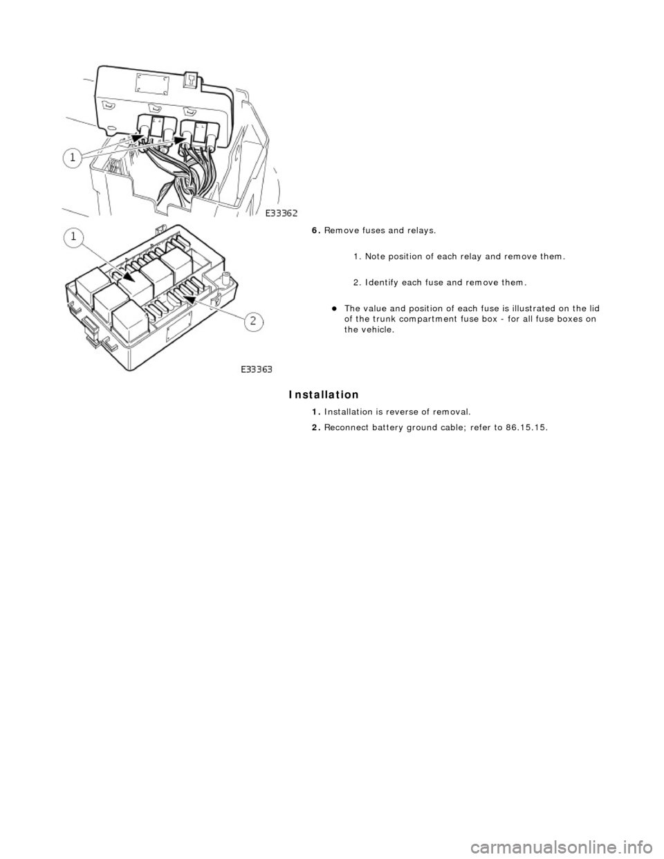
6. Remove fuses and relays.
1. Note position of each relay and remove them.
2. Identify each fu se and remove them.
The value and position of each fuse is illustrated on the lid
of the trunk compartment fuse box - for all fuse boxes on
the vehicle.
1. Installation is reverse of removal.
2. Reconnect battery ground cable; refer to 86.15.15.
Page 1984 of 2490
Module Communications Network - Central Junction Box (CJB) Removal and Installation
Removal
Installation
1. Disconnect battery ground cable; refer to 86.15.19.
2. Remove heelboard trim panel.
3. Remove positive supply power cable and displace fuse box.
1. Displace cover.
Remove nut which secures posi tive cable to fuse box.
2. Disconnect cable.
3. Remove nuts.
4. Remove fuse box.
Identify and disconnect harness connectors.
5. Remove fuses and relay.
1. Remove relay.
2. Identify each fuse and remove them.
The value and position of each fuse is illustrated on the lid of the
trunk compartment fuse box - for all fuse boxes on the vehicle.
1. Installation is reverse of removal.
2. Reconnect battery ground cable; refer to 86.15.15.
Page 1985 of 2490
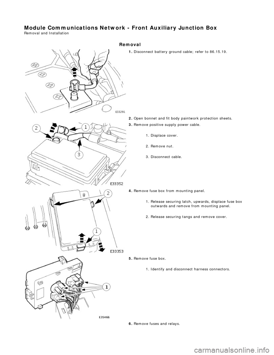
Module Communications Network - Front Auxiliary Junction Box
Removal and Installation
Removal
1. Disconnect battery ground cable; refer to 86.15.19.
2. Open bonnet and fit body pa intwork protection sheets.
3. Remove positive supply power cable.
1. Displace cover.
2. Remove nut.
3. Disconnect cable.
4. Remove fuse box fro m mounting panel.
1. Release securing latch, upwards, displace fuse box
outwards and remove from mounting panel.
2. Release securing tangs and remove cover.
5. Remove fuse box.
1. Identify and disconne ct harness connectors.
6. Remove fuses and relays.
Page 1986 of 2490
Installation
1. Note position of each relay and remove them.
2. Identify each fu
se and remove them.
The value and position of each fuse is illustrated on the lid
of the trunk compartment fuse box - for all fuse boxes on
the vehicle.
1. Installation is reverse of removal.
2. Reconnect battery ground cable; refer to 86.15.15.
Page 1987 of 2490
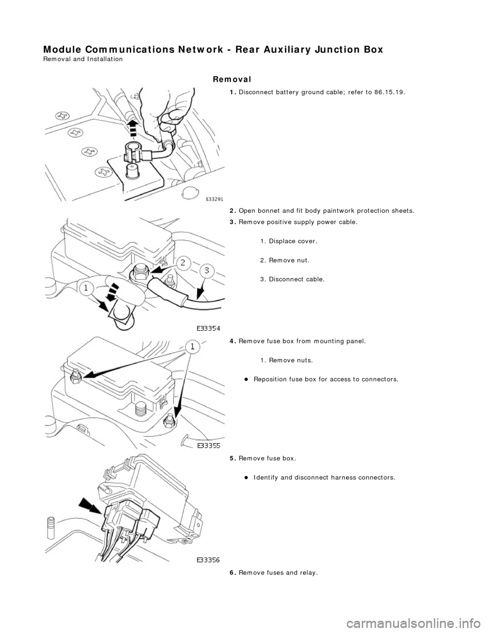
Module Communications Network - Rear Auxiliary Junction Box
Removal and Installation
Removal
1. Disconnect battery ground cable; refer to 86.15.19.
2. Open bonnet and fit body pa intwork protection sheets.
3. Remove positive supply power cable.
1. Displace cover.
2. Remove nut.
3. Disconnect cable.
4. Remove fuse box fro m mounting panel.
1. Remove nuts.
Reposition fuse box for access to connectors.
5. Remove fuse box.
Identify and disconnect harness connectors.
6. Remove fuses and relay.
Page 1988 of 2490
Installation
1. Release securing tangs and remove cover.
2. Remove relay.
3. Identify each fuse and remove them.
The value and position of each fuse is illustrated on the lid
of the trunk compartment fuse box - for all fuse boxes on
the vehicle.
1. Installation is reverse of removal.
2. Reconnect battery ground cable; refer to 86.15.15.

