Speed Sensor JAGUAR X308 1998 2.G Workshop Manual
[x] Cancel search | Manufacturer: JAGUAR, Model Year: 1998, Model line: X308, Model: JAGUAR X308 1998 2.GPages: 2490, PDF Size: 69.81 MB
Page 1835 of 2490
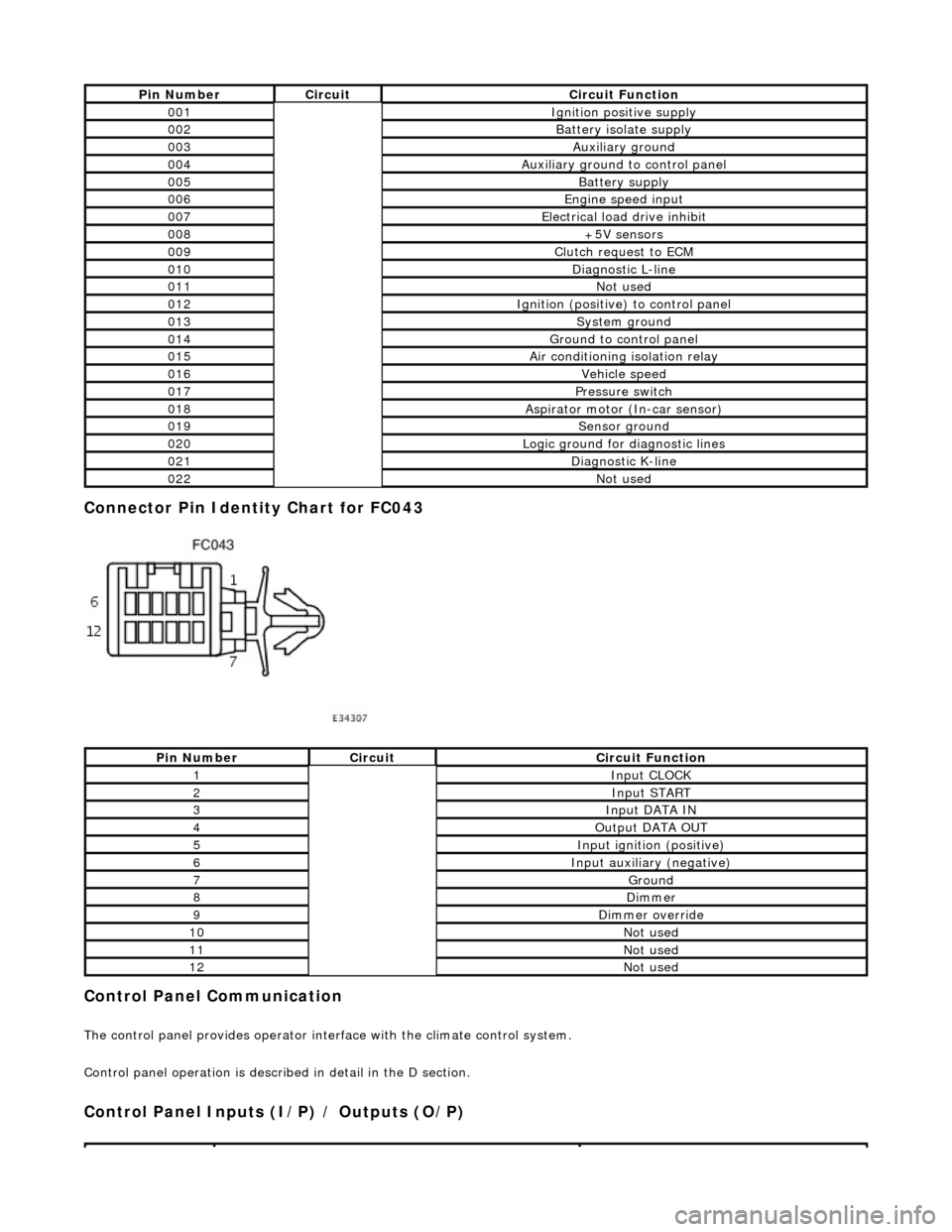
Connector Pin Identity Chart for FC043
Control Panel Communication
The control panel provides operator interface with the climate control system.
Control panel operation is described in detail in the D section.
Control Panel Inputs (I/P) / Outputs (O/P)
Pin NumberCircuitCircuit Function
001Ignition positive supply
002Battery isolate supply
003Auxiliary ground
004Auxiliary ground to control panel
005Battery supply
006Engine speed input
007Electrical load drive inhibit
008+5V sensors
009Clutch request to ECM
010Diagnostic L-line
011Not used
012Ignition (positive) to control panel
013System ground
014Ground to control panel
015Air conditioning isolation relay
016Vehicle speed
017Pressure switch
018Aspirator motor (In-car sensor)
019Sensor ground
020Logic ground for diagnostic lines
021Diagnostic K-line
022Not used
Pin NumberCircuitCircuit Function
1Input CLOCK
2Input START
3Input DATA IN
4Output DATA OUT
5Input ignition (positive)
6Input auxiliary (negative)
7Ground
8Dimmer
9Dimmer override
10Not used
11Not used
12Not used
Page 1989 of 2490
Wiring Harnesses - Wiring Harness
Description and Operation
Introduction
CAUTION: Do not use any other heat shrink sleeve other than the approved glue lined heat shrink sleeve mentioned
in the repair procedure.
The purpose of this document is to promote quick and efficient minor repair to harness connectors or cables using approved
methods and the wiring harness repair kit. Repairs may only be made to cables and connectors which have been
mechanically, not electrically damaged. It also applies wher e the whole extent of the damage can be clearly identified and
rectified.
Care and neatness are essential requir ements in making a perfect repair.
Caution:
At the time of this first issue of the Harness Repair Guide, do not approve re pairs to any of the following circuits:
Any media orientated system transport network harnesses. Supplement restraint system (SRS) firing circuits (Air bags). Link lead assembles, which are unique to safety critical circuits such as anti-lock brake system (ABS) and
thermocouple circuits. An example of this is the ABS wheel speed sensors with moulded connectors.
4. Screened cables, leads and wiring harness(s).
If any harness(s) with defective electrical connector te rminals or wires from the above circuits are a concern,
new components must be installed.
Repair Kit
CAUTION: Where the repair procedure indica tes that a glue lined heat shrink sleeve should be applied, apply sufficient
heat to the glue lined heat shrink to melt the glue in order to provide a water tight seal. Do not over heat the glue lined
heat shrink sleeve so that the wiring harness insulation becomes damaged.
The wiring harness repair kit has been produced which comprises:
Pre-terminated wiring harness(s) of different sizes and types Three sizes of butt splice connectors A selection of colored cable identification sleeves Two sizes of glue lined heat shrink sleeves Crimping pliers A wire cutter and insulation stripper An electrical connector terminal extraction handle and tips
A suitable heat source, fo r shrinking heat shrink sleeves will be required.
The pre-insulated diamond grip range of el ectrical connector terminals and in-line, butt splice connectors contained within
the wiring harness repair kit are the only acceptable product for the repairs of wi ring harnesses. The butt connectors not
only grip the wire but also the insu lation, making a very secure joint.
If an electrical connector terminal is not included in the wiring harness repair kit then approval for the repair is NOT given
and in these circumstances a new wi ring harness must be installed.
Pre-Terminated Wiring Harness( s) and Butt Splice Connectors
All pre-terminated wiring harness(s) and butt splice connectors in the wiring harness repair kit are contained in bags which
can be resealed after use. Each bag is marked with the part number of the items stored within the bag. Each storage
compartment in the wiring harness repair kit is identified with the corresponding part number. Make sure that pre-
terminated wiring harness(s) and connectors are not mixed up it is advisable to only open one bag at a time and to reseal
Page 2422 of 2490

8. Remove generator front cooling duct.
Remove bolt.
Move duct rearwards to rele ase tang from undertray.
Release front duct from rear vertical duct.
9. Remove scrivets or screws se curing undertray to bumper
cover. Discard scrivets.
10. Remove and discard tiestrap securing undertray to body
brace.
11. At each side of vehicle, remo ve and discard scrivet securing undertray to wheelarch liner.
12. Remove undertray from vehicle.
13. Remove both front road wheels. Refer to Section 100-02.
14. Remove both front road springs. Refer to 60. 20.02.
15. Disconnect wheel speed sensor harness connectors.
Page 2423 of 2490
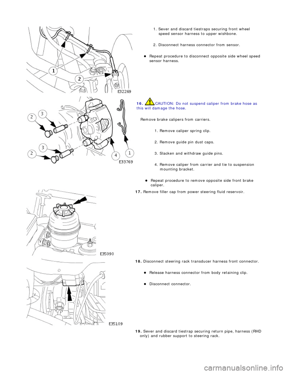
1. Sever and discard tiestraps securing front wheel
speed sensor harness to upper wishbone.
2. Disconnect harness connector from sensor.
Repeat procedure to disconnect opposite side wheel speed
sensor harness.
16. CAUTION: Do not suspend caliper from brake hose as
this will damage the hose.
Remove brake calipers from carriers.
1. Remove caliper spring clip.
2. Remove guide pin dust caps.
3. Slacken and withdraw guide pins.
4. Remove caliper from carrier and tie to suspension mounting bracket.
Repeat procedure to remove opposite side front brake
caliper.
17. Remove filler cap from power steering fluid reservoir.
18. Disconnect steering rack transducer harness front connector.
Release harness connector from body retaining clip.
Disconnect connector.
19. Sever and discard tiestrap secu ring return pipe, harness (RHD
only) and rubber support to steering rack.
Page 2436 of 2490
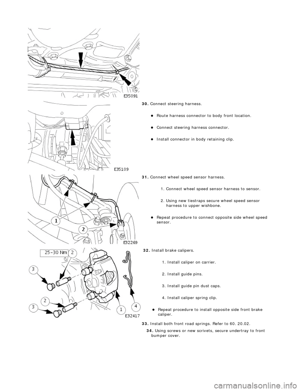
30. Connect steering harness.
Route harness connector to body front location.
Connect steering ha rness connector.
Install connector in body retaining clip.
31. Connect wheel speed sensor harness.
1. Connect wheel speed sensor harness to sensor.
2. Using new tiestraps secure wheel speed sensor harness to upper wishbone.
Repeat procedure to connect opposite side wheel speed
sensor.
32. Install brake calipers.
1. Install caliper on carrier.
2. Install guide pins.
3. Install guide pin dust caps.
4. Install caliper spring clip.
Repeat procedure to install opposite side front brake
caliper.
33. Install both front road sp rings. Refer to 60. 20.02.
34. Using screws or new scrivets , secure undertray to front
bumper cover.
Page 2463 of 2490
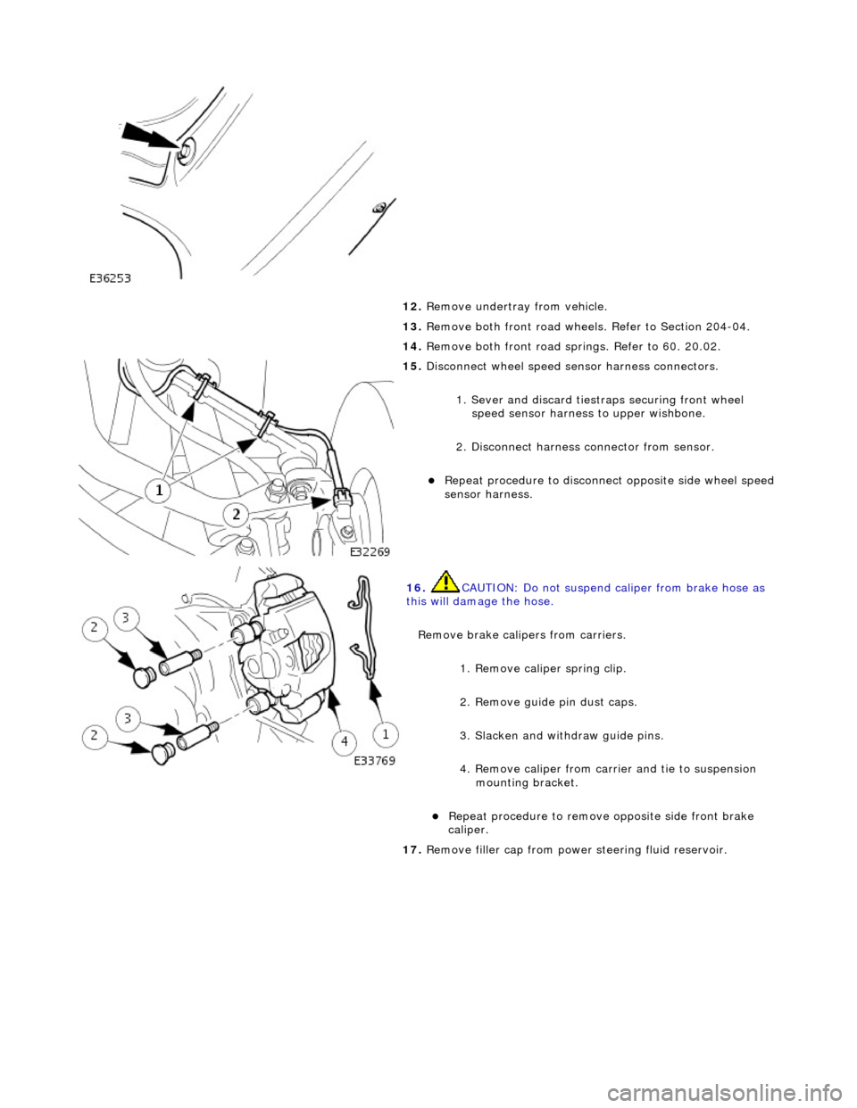
12. Remove undertray from vehicle.
13. Remove both front road wheels. Refer to Section 204-04.
14. Remove both front road springs. Refer to 60. 20.02.
15. Disconnect wheel speed sensor harness connectors.
1. Sever and discard tiestr aps securing front wheel
speed sensor harness to upper wishbone.
2. Disconnect harness connector from sensor.
Repeat procedure to disconnect opposite side wheel speed
sensor harness.
16. CAUTION: Do not suspend caliper from brake hose as
this will damage the hose.
Remove brake calipers from carriers.
1. Remove caliper spring clip.
2. Remove guide pin dust caps.
3. Slacken and withdraw guide pins.
4. Remove caliper from carrier and tie to suspension mounting bracket.
Repeat procedure to remove opposite side front brake
caliper.
17. Remove filler cap from power steering fluid reservoir.
Page 2478 of 2490
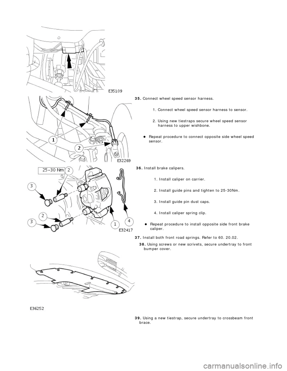
35. Connect wheel speed sensor harness.
1. Connect wheel speed sensor harness to sensor.
2. Using new tiestraps secure wheel speed sensor harness to upper wishbone.
Repeat procedure to connect opposite side wheel speed
sensor.
36. Install brake calipers.
1. Install caliper on carrier.
2. Install guide pins and tighten to 25-30Nm.
3. Install guide pin dust caps.
4. Install caliper spring clip.
Repeat procedure to install opposite side front brake
caliper.
37. Install both front road sp rings. Refer to 60. 20.02.
38. Using screws or new scrivets , secure undertray to front
bumper cover.
39. Using a new tiestrap, secure undertray to crossbeam front
brace.
Page 2485 of 2490
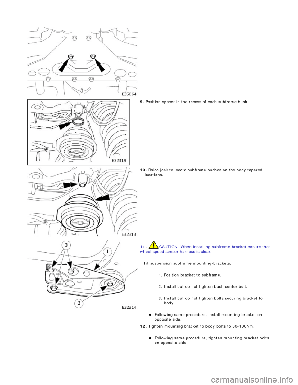
9. Position spacer in the rece ss of each subframe bush.
10. Raise jack to locate subframe bushes on the body tapered
locations.
11. CAUTION: When installing su bframe bracket ensure that wheel speed sensor harness is clear.
Fit suspension subframe mounting-brackets.
1. Position bracket to subframe.
2. Install but do not ti ghten bush center bolt.
3. Install but do not tighten bolts securing bracket to body.
Following same procedure, install mounting bracket on
opposite side.
12. Tighten mounting bracket to body bolts to 80-100Nm.
Following same procedure, ti ghten mounting bracket bolts
on opposite side.