key JAGUAR X308 1998 2.G Workshop Manual
[x] Cancel search | Manufacturer: JAGUAR, Model Year: 1998, Model line: X308, Model: JAGUAR X308 1998 2.GPages: 2490, PDF Size: 69.81 MB
Page 53 of 2490
Jacking and Lifting - Vehicle Recovery
Description an
d Operation
• NOTE: Prior to recovery, ensure that the vehicle keys are available and the security system disarmed.
Vehicle recovery methods are:
By fl
at-bed transporter.
By rear suspended tow.
By emergency to
wing for
very short distances.
Gears
hift Interlock
The
gear selector lever can only be moved
from the Park position by turning the igni tion key to position II and depressing
the brake pedal.
To remove the key from the ignition switch, the gear select or lever must be moved to the Park position. With the key
removed, the gear selector is locked in the Park position.
The selector lever can be manually unlocked from the Park position in the event of electrical failure or when moving the
vehicle without power. Refer to the general procedure in this section.
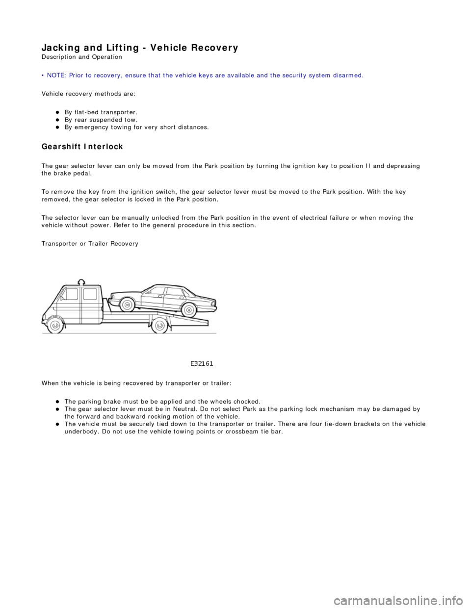
Transporter or Trailer Recovery
When the vehicle is being recove red by transporter or trailer:
The parking brake must be
be applied and the wheels chocked.
The
gear selector lever must be in Ne
utral. Do not select Park as the park ing lock mechanism may be damaged by
the forward and backward rocking motion of the vehicle.
The ve
hicle must be securely tied down to the transporter or
trailer. There are four tie-down brackets on the vehicle
underbody. Do not use the vehicle towing points or crossbeam tie bar.
Page 54 of 2490
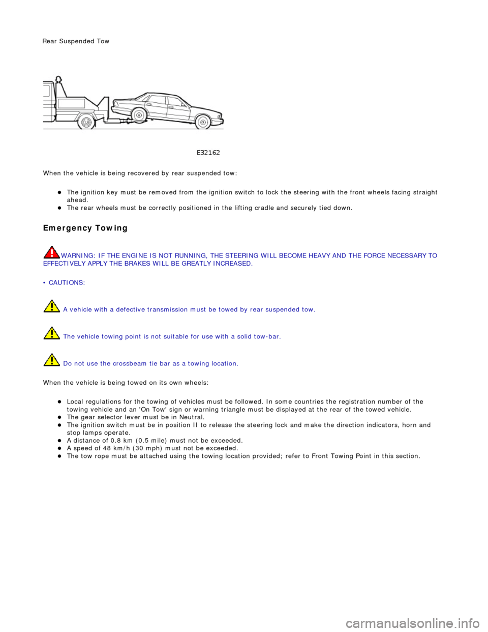
Wh en t
he vehicle is being reco
vered by rear suspended tow:
The ignition key must be remo ved from the ig
nition switch to lock the stee
ring with the front wheels facing straight
ahead.
The re ar
wheels must be
correctly positioned in the lifting cradle and securely tied down.
Em
ergency Towing
WARNING: IF THE
ENGINE IS NOT
RUNNING, THE STEERING WILL BECOME HEAVY AND THE FORCE NECESSARY TO
EFFECTIVELY APPLY THE BRAKES WILL BE GREATLY INCREASED.
• CAUTIONS:
A vehicle with a defective transmission must be towed by rear suspended tow.
The vehicle towing point is not suit able for use with a solid tow-bar.
Do not use the crossbeam tie bar as a towing location.
When the vehicle is being towed on its own wheels:
Loc a
l regulations for the towing of ve
hicles must be followed. In some co untries the registration number of the
towing vehicle and an 'On Tow' sign or warning triangle must be displayed at the rear of the towed vehicle.
The gear s
elector lever
must be in Neutral.
The
ignition switch must be in positi
on II to release the steering lock and make the direction indicators, horn and
stop lamps operate.
A di
stance of 0.8 km (0.5 mi
le) must not be exceeded.
A spe
ed of 48 km/h (30 mph) must not be exceeded.
The tow rope must be attached using th
e towi
ng location provided; refer to Front Towing Point in this section.
Rear Su
spended
Tow
Page 108 of 2490
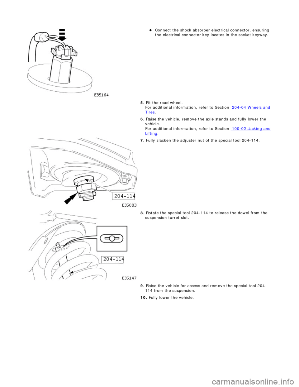
Connect
the shock absorber elec
trical connector, ensuring
the electrical connector key locates in the socket keyway.
5. Fit the road wheel.
For additional informat ion, refer to Section 204
-04 W
heels and
Tire
s.
6. Ra
ise the vehicle, remove the axle stands and fully lower the
vehicle.
For additional informat ion, refer to Section 100
-02
Jacking and
Liftin
g.
7. Ful l
y slacken the adjuster nut of the special tool 204-114.
8. Rot a
te the special tool 204-114 to release the dowel from the
suspension turret slot.
9. Raise the vehicle for access an d remove the special tool 204-
114 from the suspension.
10. Fully lower the vehicle.
Page 178 of 2490
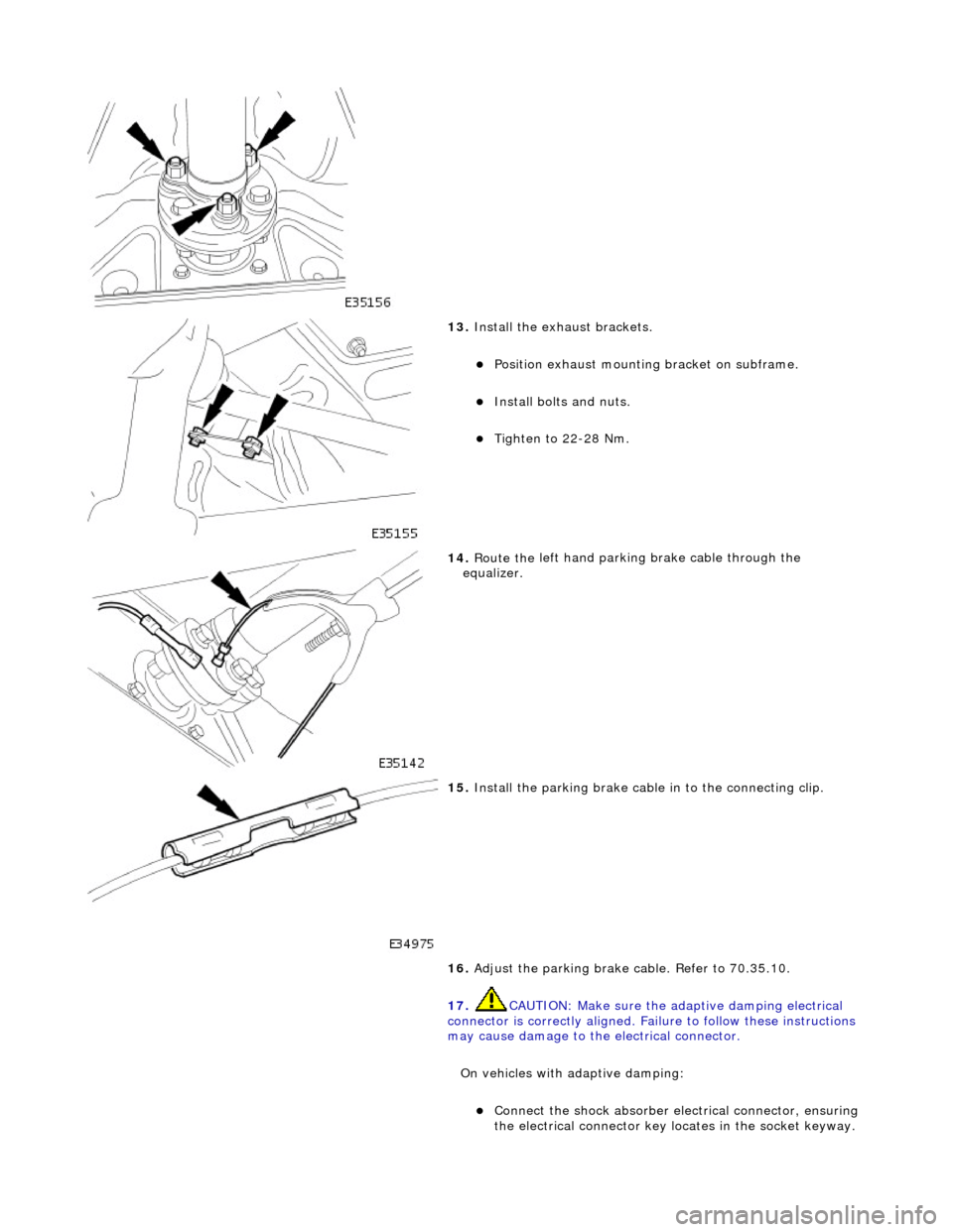
13. Inst
all the exhaust brackets.
Position exha
ust mounting bracket on subframe.
Inst
al
l bolts and nuts.
Tigh
te
n to 22-28 Nm.
14 . Route the
left hand parking brake cable through the
equalizer.
15 . Install th
e parking brake cable
in to the connecting clip.
16. Adjust the parking brake cable. Refer to 70.35.10.
17. CAUTION: Make sure the adaptive damping electrical
connector is correctly aligned. Failu re to follow these instructions
may cause damage to the electrical connector.
On vehicles with adaptive damping:
Conne ct
the shock absorber elec
trical connector, ensuring
the electrical connector key locates in the socket keyway.
Page 188 of 2490
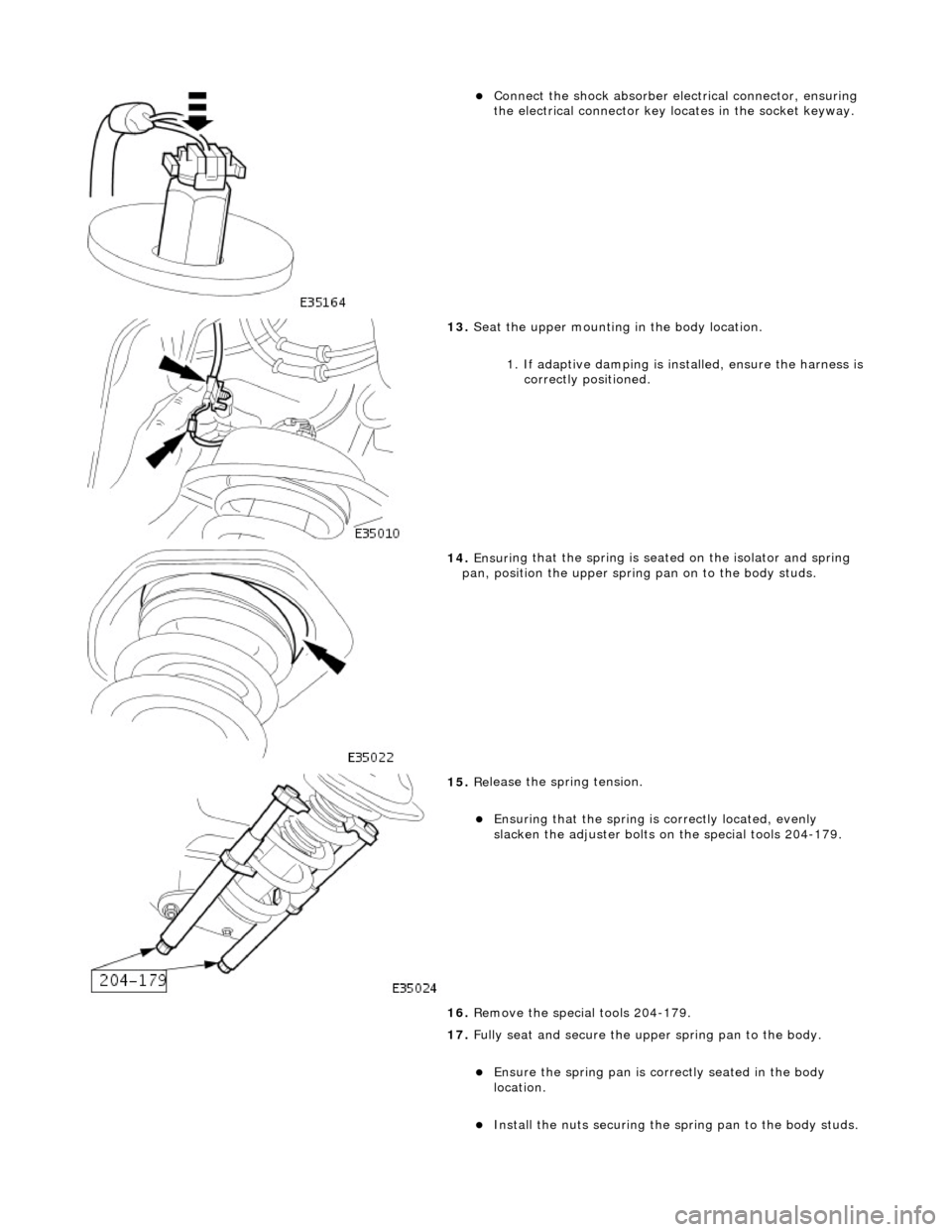
Connect
the shock absorber elec
trical connector, ensuring
the electrical connector key locates in the socket keyway.
13. Seat
the upper mounting in the body location.
1. If adaptive damping is installed, ensure the harness is
correctly positioned.
14 . Ensuri
ng that the spri
ng is seated on the isolator and spring
pan, position the u pper spring pan on to the body studs.
15 . Re
lease the spring tension.
Ensuri
ng that the spri
ng is
correctly located, evenly
slacken the adjuster bolts on the special tools 204-179.
16. Remove the special tools 204-179.
17. Fully seat and secure the u pper spring pan to the body.
Ensure the spring pan i
s correctly seated in the body
location.
Inst al
l the nuts securing the sp
ring pan to the body studs.
Page 204 of 2490
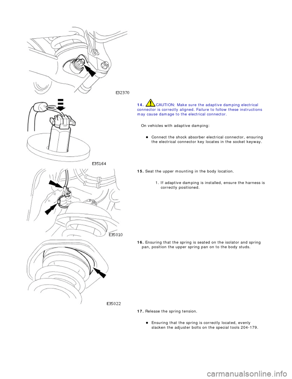
14. CAUTI
ON: Make sure the adaptive damping electrical
connector is correctly aligned. Failu re to follow these instructions
may cause damage to the electrical connector.
On vehicles with adaptive damping:
Conne ct
the shock absorber elec
trical connector, ensuring
the electrical connector key locates in the socket keyway.
15 . Seat
the upper mounting in the body location.
1. If adaptive damping is installed, ensure the harness is
correctly positioned.
16 . Ensuri
ng that the spri
ng is seated on the isolator and spring
pan, position the u pper spring pan on to the body studs.
17. Release the spring tension.
Ensuring that the spri
ng is
correctly located, evenly
slacken the adjuster bolts on the special tools 204-179.
Page 263 of 2490
O
ne locking wheel nut is fitted to each road wheel and can on
ly be removed by using the correctly coded socket. For road
wheels with exposed wheel nuts, each locking wheel nut is provided with a cover, which is removed using the cover removal
tool.
Locking wheel nuts have different coded keyway combinations with corresponding coded sockets. The correct socket, and
cover removal tool are supplied with the vehicle toolkit. Sets of sockets are available to Jaguar dealers.
Temporary Spare Wheel
•
NOTE: When using this type of spare wheel note that:
Speed
must not exceed 80 km/h (50 mph).
The normal ro
ad wheel must be reinstalled as soon as possible.
On
ly one temporary wheel may be installed to the vehicle.
Tracti
on control (where fitted
) must be switched OFF.
In certain markets, the spare wheel supplied with the vehicle is of the temporary-use type, it is narrower than the normal
road wheel and takes up less room in the luggage compartment.
Tire
s
The
radial ply tires shown in the 204-04
Specification Section are recommended by Jaguar to meet the high speed
performance of the vehicle. Only tires of identical specification may be fitted as replacements. Unde r no circumstances must
cross-ply tires be fitted.
Tire Inflation Pressures
Al
l recommended tires, including winter tire
s, must be inflated to the pressures shown in the 204-04 Specification Section.
Inflation pressures must only be checked when the tires are cold.
Tire Replac
ement and Wheel-Interchanging
W
hen renewal of tires is necessary, it is
preferable to fit a complete set. If two replacement tires are fitted (to one axle),
they must be of the same manufacturer and type as those on the other axle.
No attempt must be made to interchange wh eels from the front to the rear or vice-versa, as wear produc es a characteristic
pattern on each tire depending upon its po sition on the vehicle. If this position is changed after wear has occurred, the
performance of the tire w ill be adversely affected.
It should be remembered that new tires must be balanced befo re installing to the vehicle.
Win
ter Tires
•
NOTE: Speed must not exceed 210 km/h (131 mph) when winter tires are installed.
Jaguar recommended winter tires as specified in 204-04 Specification Section must only be fitted in complete four-wheel
sets of the same type and size.
Snow Chains and Spike Spider Traction System
Jagu
ar recommended snow chains, must on
ly be installed when using 16 inch wheels with 255/60 R16 winter tires.
• NOTE: When using snow chains or the spike spider traction system, note that:
Snow ch
ains and the spike spider
traction system must only be fitted to the rear wheels.
O
nly Jaguar recommended snow chains and spik
e spider traction system must be used.
The m
aximum permissible speed with winter tires and snow chains or the spike spider traction system fitted is 48
km/h (30 mph).
Tracti
on control (where fitted) must be
switched OFF when using snow chains or the spike spider traction system.
Page 296 of 2490
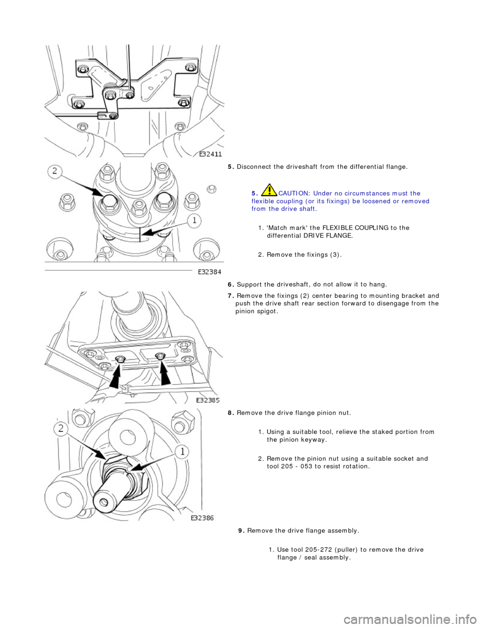
5. Disconne
ct the driveshaft fr
om the differential flange.
5. CAUTION: Under no circumstances must the
flexible coupling (or its fixings) be loosened or removed
from the drive shaft.
1. 'Match mark' the FLEX IBLE COUPLING to the
differential DRIVE FLANGE.
2. Remove the fixings (3).
6. Support the d
riveshaft, do not allow it to hang.
7. Re
move the fixings (2) center
bearing to mounting bracket and
push the drive shaft rear sectio n forward to disengage from the
pinion spigot.
8. Remove the drive flange pinion nu
t.
1. Using a suitable tool, re lieve the staked portion from
the pinion keyway.
2. Remove the pinion nut using a suitable socket and tool 205 - 053 to resist rotation.
9. Remove the drive flange assembly.
1. Use tool 205-272 (puller) to remove the drive flange / seal assembly.
Page 469 of 2490
Buzz (E
lectrical)
A
different steering buzz can be caused by
pulse width modulated (PWM) electric actuators used in variable assist steering
systems. This buzz is felt by turning the ignition key to run without starting the engine and holding onto the steering wheel.
In extreme cases, the buzz can be felt with the engine running also.
Column/Steering Wheel
Shake
Column shake is a low f
requenc
y vertical vibration excited by primary engine vibrations.
Nibble (Shimm
y)
Steeri
ng nibble is a rotary oscillation or
vibration of the steering wheel, which can be excited at a specific vehicle speed.
Nibble is driven by wheel and tire imbalance exciting a suspensi on recession mode, which then translates into steering gear
travel and finally steering wheel nibble.
Shudder (Judd
er)
Shudder i
s a low frequency oscillation of th
e entire steering system (tire, wheels, st eering gear and linkage, etc.) when the
vehicle is steered during static-park or at low sp eeds. Shudder is very dependent on road surface.
Torque Ri
pple
Torque rippl
e is a concern with Electric Power Steering (EPS) sy
stems. Torque ripple is most evident at static-park steering
the wheel very slowly from lock to lock. Torque ripple is primarily caused by motor commutation.
Torque/Veloc
ity Variation
(Phasing/Effort Cycling)
Steeri
ng wheel torque variation oc
curring twice in one revolution is normally as a result of problems with the lower steering
column (intermediate shaft), but foul cond itions generally result in either constant stiffnes s or single point stiffness.
Depending upon the orientation of the joints, the steering can fe el asymmetric (torque falling off in one direction and rising
in the other) or else it can simply have pronounced peaks and troughs as the steering moves from lock to lock.
Wheel Fight
(Kick Back)
W
heel fight is excess feedback of sudden road forces through th
e steering system and back to the driver. It is evaluated at
all vehicle speeds over cobblestones, rough roads, and potholes . The tires, wheels, and suspension generate forces into the
steering systems. Steering friction, hydraulic damping, hydr aulic compliance, mechanical compliance, steering ratio, and
assist gain all affect how much is transmitted to the driver.
Stee
ring Linkage
CAUTI
ON: Steering gear boots must be
handled carefully to avoid damage. Use new clamps when installing steering
gear boots.
Inspect the boots for cuts, deterioration, tw isting or distortion. Check the steering gear boots to make sure they are tight.
Install new boots or clamps as necessary.
• NOTE: The following steps must be carried out with assistance.
1. 1. With the wheels in the straight ahead po sition, gently turn the steering wheel to the left and the right to check for
free play.
2. 2. Free play should be between 0 and 6 mm (0 and 0.24 in) at the steering wheel rim. If the free play exceeds this
limit, either the ball joints are worn, the lower steering column joints are worn or the backlash of the steering gear
is excessive.
Page 508 of 2490
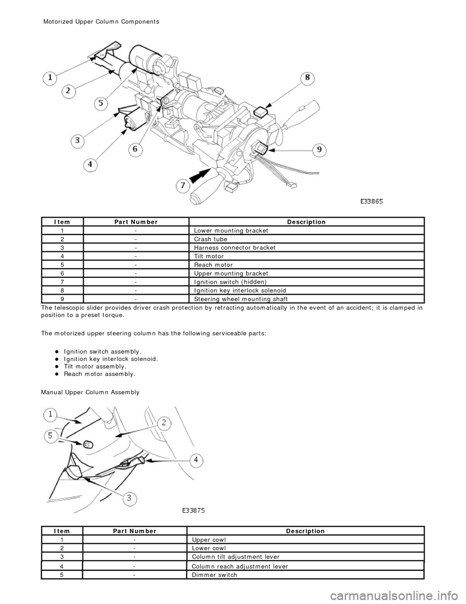
The te
lescopic slider provides driver crash
protection by retracting automatically in the event of an accident; it is clamped in
position to a preset torque.
The motorized upper steering column has the following serviceable parts:
Igniti
on switch assembly.
Igni
ti
on key interlock solenoid.
Ti
lt
motor assembly.
Reach motor assembly.
Manu al Upper Column Assembly
Ite
m
Par
t
Number
De
scr
iption
1-L
o
wer mounting bracket
2-Crash tube
3-Harnes
s c
onnector bracket
4-Tilt motor
5-Reach m
otor
6-Upper
moun
ting bracket
7-Ignition switc
h
(hidden)
8-Igni
ti
on key interlock solenoid
9-S
t
eering wheel mounting shaft
It
e
m
Par
t
Number
De
scr
iption
1-Upper
cowl
2-Lower cowl
3-Colu
mn tilt adjustment lever
4-Col
u
mn reach adjustment lever
5-Di
mm
er switch
Motorized Upper Co
lumn Components