steering JAGUAR X308 1998 2.G Workshop Manual
[x] Cancel search | Manufacturer: JAGUAR, Model Year: 1998, Model line: X308, Model: JAGUAR X308 1998 2.GPages: 2490, PDF Size: 69.81 MB
Page 2016 of 2490

Installation
slacken and remove module to bracket securing screws.
9.
Remove seat control module.
1. Disconnect harness multiplugs from module.
2. Withdraw module from seat
1. Position control module at seat and connect harness
multiplugs.
2. Position control module on mounting bracket and fit and
tighten securing screws.
3. Position control module/mountin g bracket assembly on seat
frame and fit and tighten securing screw.
4. Position seat over se curing bolt holes.
5. Fit and tighten seat front securing bolts
6. Fit and tighten seat re ar securing bolts.
7. Connect ground cable to battery terminal and fit battery cover.
Refer to 86.15.15.
8. Return seat to original position.
9. Return steering column to original position.
Page 2021 of 2490

Body System - General Information - Body
Description and Operation
This section covers the following areas of the vehicle body:
Front end body panels
Body closures
Aperture seals
Door seals
Instrument panel, console and radio
Centre console
Handles, locks, latches and mechanisms
Wipers and washers
Glass, frames and mechanisms
Fascia
Fuel filler flap assembly
Sun visors
Seating
Interior trim and ornamentation
Exterior trim and ornamentation
Rear view mirrors
Rear parcel tray
Roof console
Bumpers
Occupant restraints
Sliding roof
Steering column cowl
Underscuttle pad
Front End Body Panels
A false bulkhead together with two insulation covers, are installed between the engine compartment and the BIW front
bulkhead to provide optimum insulation ag ainst noise and heat intrusion. Two plenum braces bolted between the BIW upper toeboards and the plenum further increase bodyshell structural integrity. The plastic ra diator grill and vane block achieve
weight reductions over steel parts and provid e high resistance to front end corrosion.
Page 2122 of 2490

Seating - Front Seat
Removal and Installation
Removal
1. Move the seat fully rearward and slacken and remove the
front securing bolts.
2. Move steering wheel to fully forward position.
3. Ensure that squab is fully upright, then move the seat fully
forward.
4. WARNING: FOLLOWING DISCONNECTION OF THE
BATTERY A PERIOD OF AT LEAST ONE MINUTE MUST BE
ALLOWED TO ELAPSE BEFORE WORKING ON A FRONT SEAT WITH
A SIDE AIRBAG FITTED.
Remove battery cover and disc onnect ground cable from
battery terminal. Refer to 86.15.19.
5. Remove the slider covers an d slacken and remove the two
rear securing bolts.
6. Supporting and positioning the seat for access, disconnect
multiplugs.
Disconnect side air bag harness multiplug.
Release from retaining brackets and disconnect seat
harness multiplugs.
Disconnect seat control module harness multiplug.
Cut through and remove any ti es securing harnesses to
seat frame.
7. NOTE: Securing bolt remains captive with belt anchor.
Slacken and remove seat be lt anchor securing bolt.
Page 2239 of 2490

Instrument Panel and Console - Instrument Cluster Finish Panel
Removal and Installation
Removal
Installation
1.
Turn ignition key to position II.
2. Move steering column to lowest and fully extended position.
3. Turn ignition key to position 'O'.
4. Remove battery cover and disc onnect ground cable from
battery terminal. Refer to 86.15.15.
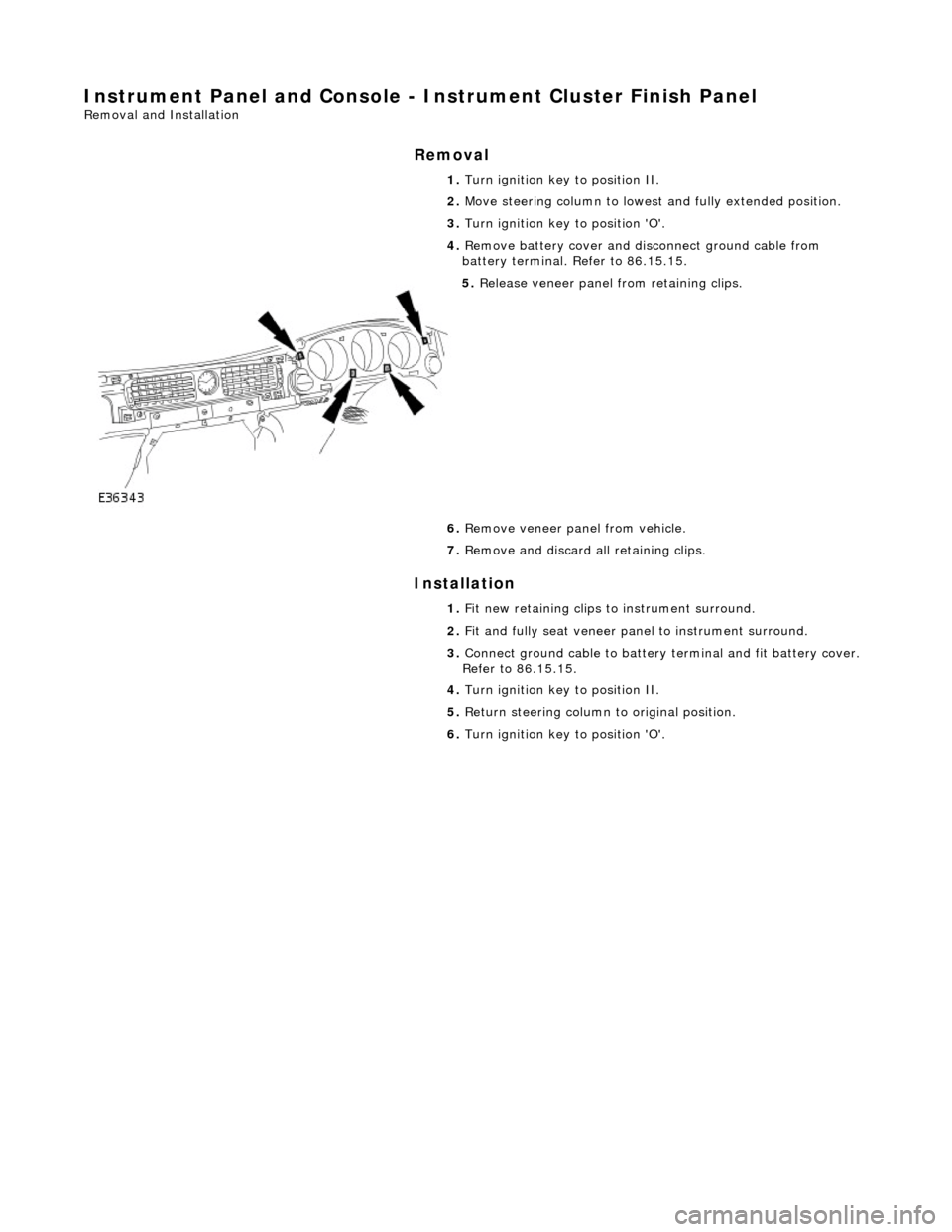
5. Release veneer panel from retaining clips.
6. Remove veneer panel from vehicle.
7. Remove and discard all retaining clips.
1. Fit new retaining clips to instrument surround.
2. Fit and fully seat veneer pa nel to instrument surround.
3. Connect ground cable to battery terminal and fit battery cover.
Refer to 86.15.15.
4. Turn ignition key to position II.
5. Return steering column to original position.
6. Turn ignition key to position 'O'.
Page 2240 of 2490

Instrument Panel and Console - Instrument Cluster Finish Panel Bezel
Removal and Installation
Removal
1. Adjust steering column to full y extended and lowered position.
2. Remove battery cover and disc onnect ground cable from
battery terminal. Refer to 86.15.19.
3. Remove veneer from instrument panel. Refer to 76.47.24.
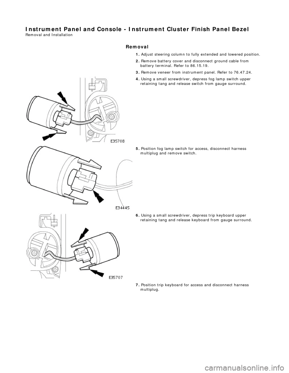
4. Using a small screwdriver, de press fog lamp switch upper
retaining tang and release sw itch from gauge surround.
5. Position fog lamp switch fo r access, disconnect harness
multiplug and remove switch.
6. Using a small screwdriver, depress trip keyboard upper
retaining tang and release ke yboard from gauge surround.
7. Position trip keyboard for ac cess and disconnect harness
multiplug.
Page 2241 of 2490

Installation
8. Slacken and remove four screws securing major gauge
module/surround to fascia and withdraw surround.
1. Position major gauge surround on panel, routing harness
multiplugs through apertures.
2. Fit and tighten screws securing major gauge module/surround
to fascia.
3. Connect harness multiplug to tr ip keyboard and fit and fully
seat keyboard in gauge surround, ensuring correct location of
retaining tangs
4. Connect harness multiplug to fog lamp switch and fit and fully
seat switch in gaug e surround, ensuring correct location of
tangs.
5. Fit veneer panel. Refer to 76.47.24.
6. Connect ground cable to battery terminal and fit battery cover.
Refer to 86.15.15.
7. Return steering column to original position.
Page 2242 of 2490

Instrument Panel and Console - Instrument Panel
Removal and Installation
Removal
1. Turn ignition switch to position II.
2. Motor driver and front passenger seats rearward.
3. Position steering wheel in stra ight ahead position and fully
lower and extend steering column.
4. Turn ignition switch to position O.
5. Remove battery cover and disc onnect ground cable from
battery terminal. Refer to 86.15.19.
6. Remove 'J' gate finish er. Refer to 76.25.24.
7. Remove 'J' gate finisher retain ing panel. Refer to 76.25.26.
8. Remove centre console veneer panel. Refer to 76.47.26.
9. Disconnect and remove radio.
10. Remove centre console switch module. Refer to 86.80.32.
11. Remove centre console. Refer to 76.25.01.
12. Slacken and remove centre cons ole vent duct rear securing
screw and withdraw duct assemb ly from air conditioning unit
manifold.
13. WARNING: BEFORE ANY AIRBAG/SRS SERVICE IS
PERFORMED, AT LEAST ONE MINUTE MUST ELAPSE AFTER
DISCONNECTION OF THE BATTERY CABLE, TO ALLOW
DISSIPATION OF BACK-UP POWER SUPPLY ENERGY.
Remove driver airbag. Refer to 76.73.39.
14. Remove steering wheel. Refer to Section 211-04.
15. Remove steering column lo wer cowl. Refer to 76.46.03.
16. Remove steering column u pper cowl. Refer to 76.46.02.
17. Remove driver side unders cuttle. Refer to 76.46.11.
18. Remove combined windshield wiper/washer switch and
audible warning speaker assembly. Refer to 86.65.42.
19. Remove glovebox. Refer to 76.52.03.
20. Remove 'A' post lower trim pads. refer to 76.13.30.
21. Carefully withdraw driver stowage bin trim, remove bin
securing screw and remove bin from facia.
Page 2243 of 2490

22. Accessing via driver stowage bin aperture, disconnect facia
harness to centre console harness multiplugs.
23. Release driver side facia harness to passenger compartment
harness multiplug retaining le ver and disconnect multiplug.
24. From RH side footwell, remove nut securing facia harness
ground eyelet to tunnel front stud and disconnect eyelet from
stud.
25. Remove steering column reac h adjustment motor harness
multiplug (yellow) from retain ing bracket and disconnect
multiplug.
Page 2244 of 2490

26. Remove steering column tilt adjustme nt motor harness
multiplug from retaining bracke t and disconnect multiplug.
27. Remove bolt securing facia moun ting bracket to RH side of
tunnel.
28. Remove facia RH end aperture trim pad.
29. CAUTION: The 'A' post facia mounting brackets are pre-
set to the body and must no t under any circumstances be
disturbed.
Remove two bolts securing facia to RH 'A' post mounting
bracket.
Page 2262 of 2490

54. Install radio. Refer to 86.50.03.
55. Install facia centre veneer panel. Refer to 76.47.06.
56. Install centre console veneer panel. Refer to 76.47.26.
57. Install 'J' gate finisher retain ing panel. Refer to 76.25.26.
58. Install 'J' gate surround. Refe r to 76.25.24, Section 307-05A
(N/A), 307-05B (S/C).
59. Connect steering column tilt motor harness multiplug and
install multiplug on retaining bracket.
60. Connect steering column reac h motor harness multiplug and
install multiplug on retaining bracket.
61. Position ground cable eyelet on RH 'A' post stud and install
securing nut.
62. Connect driver side facia harn ess to passenger compartment
harness multiplug and secure with retaining lever.
63. Connect driver side facia harness to console harness
multiplugs.