service JAGUAR X308 1998 2.G Workshop Manual
[x] Cancel search | Manufacturer: JAGUAR, Model Year: 1998, Model line: X308, Model: JAGUAR X308 1998 2.GPages: 2490, PDF Size: 69.81 MB
Page 1801 of 2490
Condenser:
Multi-pass fin-over-tube type, mounted in front of the engine cooling pack and directly to the radiator.
Pressure (Bitron) switch:
Located in the discharge pipe. Provides a signal, via the A/CCM, to th e ECM, to disengage the compressor clut ch should the refrigerant pressure be
< 2 bar or > 30 bar.
Provides a hard-wired signal to the ECM, to switch the cool ing fans to HIGH speed at 22 bar rising pressure and to
LOW speed at 17,5 bar falling pressure.
Provides a hard-wired signal to the ECM, to switch the radiator cooling fans to LOW speed at 12 bar rising pressure
and to switch the fans OFF at 8 bar falling pressure.
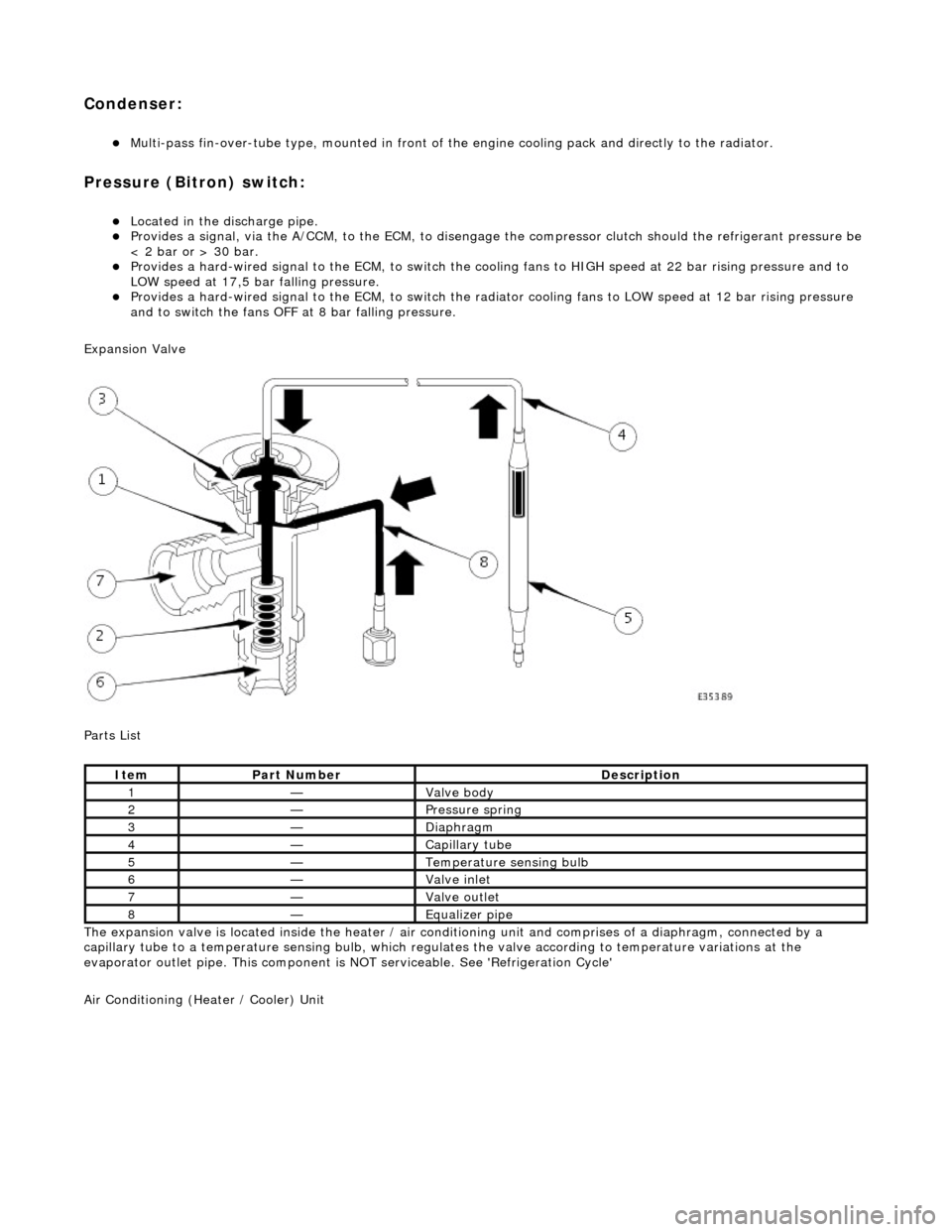
Expansion Valve
Parts List
The expansion valve is located inside the heater / air conditioning unit and comprises of a diaphragm, connected by a
capillary tube to a temperat ure sensing bulb, which regulates the valve according to temperature variations at the
evaporator outlet pipe. This component is NOT serviceable. See 'Refrigeration Cycle'
Air Conditioning (Heater / Cooler) Unit
ItemPart NumberDescription
1—Valve body
2—Pressure spring
3—Diaphragm
4—Capillary tube
5—Temperature sensing bulb
6—Valve inlet
7—Valve outlet
8—Equalizer pipe
Page 1808 of 2490

Air Conditioning - Condenser Core
Removal and Installation
Removal
1. Disconnect battery ground cable (IMPORTANT, see SRO
86.15.19 for further information).
2. Drain radiator coolant only; refer to 26.10.01 or (SC)
26.10.01.
3. Recover refrigerant from air co nditioning system; refer to
82.30.30.
4. Release both gas struts, set the engine cover fully forward to
the service access position an d support with a wooden (or
similar) strut.
5. CAUTION: Take care not to damage hood or radiator
grille.
Remove twin fan and motor as sembly; refer to 26.25.12.
6. Disconnect radiator bleed hose.
Release connection.
7. Remove retaining clip which secures transmission oil cooler
upper and lower pipes.
8. Disconnect transmission oil cooler lower pipe from radiator.
1. Release union nut and disconne ct pipe.
Discard O-ring seal.
2. Install suitable blanking plugs.
9. From above the vehicle, discon nect transmission oil cooler
upper pipe from radiator.
1. Release union nut and disconne ct pipe.
Discard O-ring seal.
2. Install suitable blanking plugs.
Page 1882 of 2490
Generator and Regulator - Generator
Description and Operation
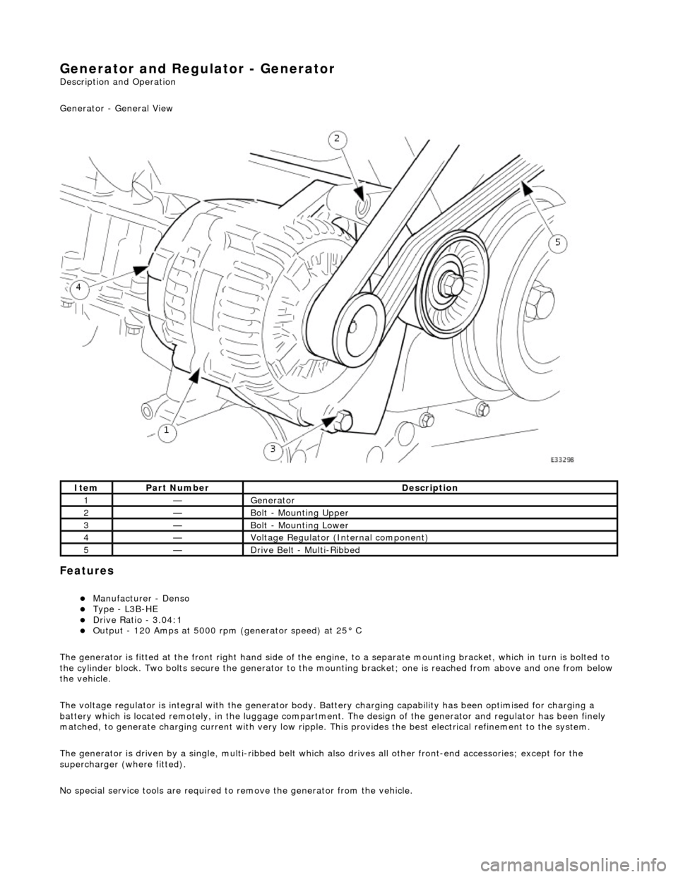
Generator - General View
Features
Manufacturer - Denso Type - L3B-HE Drive Ratio - 3.04:1 Output - 120 Amps at 5000 rpm (generator speed) at 25° C
The generator is fitted at the front right hand side of the engine, to a sepa rate mounting bracket, which in turn is bolted to
the cylinder block. Two bolts secure th e generator to the mounting bracket; one is reached from above and one from below
the vehicle.
The voltage regulator is integral with th e generator body. Battery charging capabi lity has been optimised for charging a
battery which is located remotely, in the luggage compartment. The design of the generator and regulator has been finely
matched, to generate charging current with very low ripple. This provides the best electrical refinement to the system.
The generator is driven by a single, multi-ribbed belt which also drives all other front-e nd accessories; except for the
supercharger (where fitted).
No special service tools are required to remove the generator from the vehicle.
ItemPart NumberDescription
1—Generator
2—Bolt - Mounting Upper
3—Bolt - Mounting Lower
4—Voltage Regulator (Internal component)
5—Drive Belt - Multi-Ribbed
Page 1883 of 2490
Belt tension is achieved by an automatic tensioner; neither the belt nor the tensioner require service apart from checking
the belt wear indicators at each normal service interval.
The minimum service life of the drive belt is 100,000 miles.
Never apply oil to the belt or to the belt tensioner.
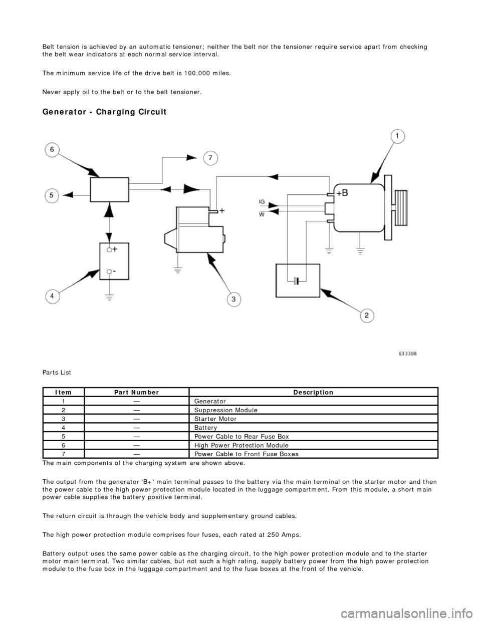
Generator - Charging Circuit
Parts List
The main components of the charging system are shown above.
The output from the generator 'B+' main te rminal passes to the battery via the main terminal on the starter motor and then
the power cable to the high power protection module located in the luggage compartment. From this module, a short main
power cable supplies the ba ttery positive terminal.
The return circuit is through the vehicle body and supplementary ground cables.
The high power protection mo dule comprises four fuses, each rated at 250 Amps.
Battery output uses the same power cable as the charging circ uit, to the high power protection module and to the starter
motor main terminal. Two similar cables, but not such a high rating, supply battery power from the high power protection
module to the fuse box in the luggage compartment an d to the fuse boxes at the front of the vehicle.
ItemPart NumberDescription
1—Generator
2—Suppression Module
3—Starter Motor
4—Battery
5—Power Cable to Rear Fuse Box
6—High Power Protection Module
7—Power Cable to Front Fuse Boxes
Page 1886 of 2490
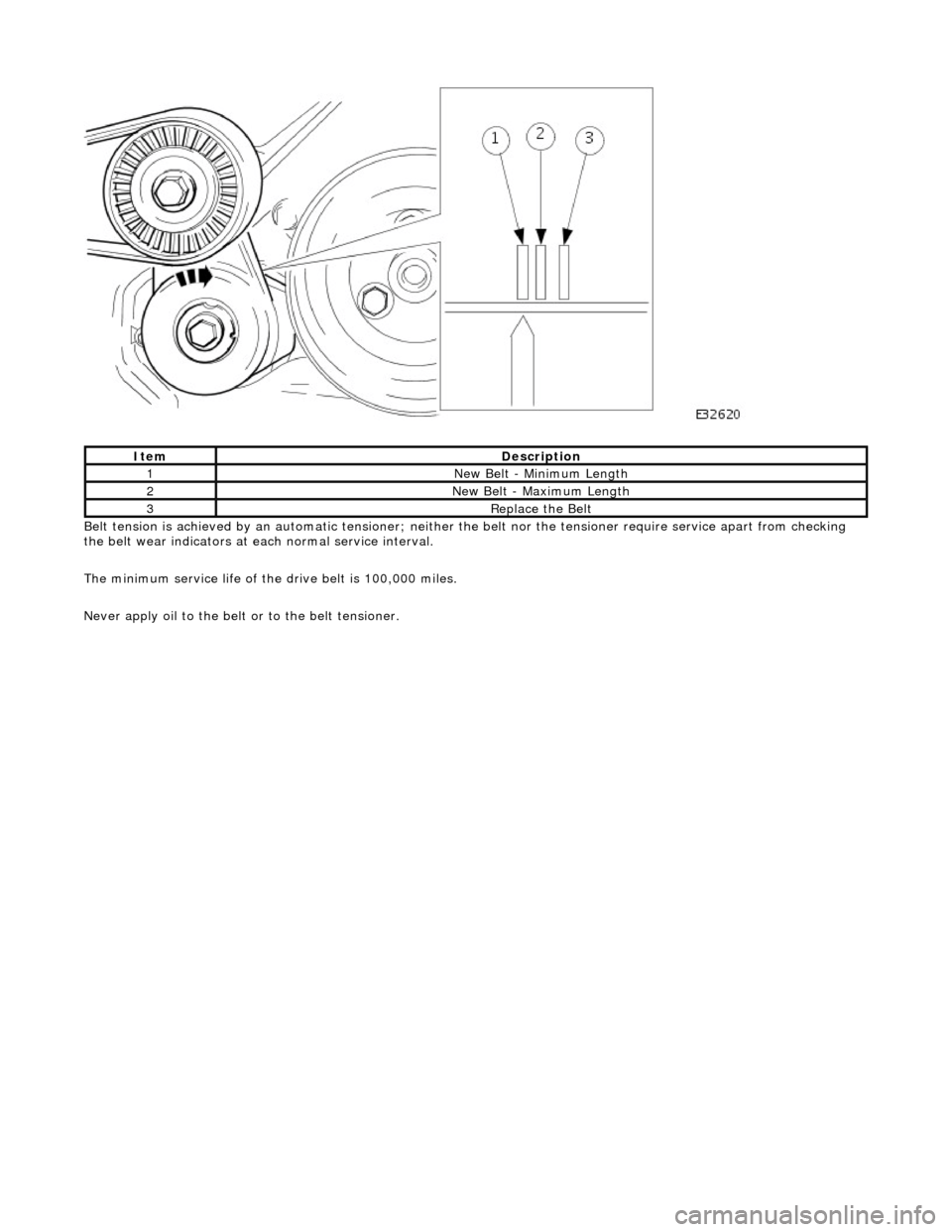
Belt tension is achieved by an automatic tensioner; neither the belt nor the tensioner require service apart from checking
the belt wear indicators at each normal service interval.
The minimum service life of the drive belt is 100,000 miles.
Never apply oil to the belt or to the belt tensioner.
ItemDescription
1New Belt - Minimum Length
2New Belt - Maximum Length
3Replace the Belt
Page 2242 of 2490

Instrument Panel and Console - Instrument Panel
Removal and Installation
Removal
1. Turn ignition switch to position II.
2. Motor driver and front passenger seats rearward.
3. Position steering wheel in stra ight ahead position and fully
lower and extend steering column.
4. Turn ignition switch to position O.
5. Remove battery cover and disc onnect ground cable from
battery terminal. Refer to 86.15.19.
6. Remove 'J' gate finish er. Refer to 76.25.24.
7. Remove 'J' gate finisher retain ing panel. Refer to 76.25.26.
8. Remove centre console veneer panel. Refer to 76.47.26.
9. Disconnect and remove radio.
10. Remove centre console switch module. Refer to 86.80.32.
11. Remove centre console. Refer to 76.25.01.
12. Slacken and remove centre cons ole vent duct rear securing
screw and withdraw duct assemb ly from air conditioning unit
manifold.
13. WARNING: BEFORE ANY AIRBAG/SRS SERVICE IS
PERFORMED, AT LEAST ONE MINUTE MUST ELAPSE AFTER
DISCONNECTION OF THE BATTERY CABLE, TO ALLOW
DISSIPATION OF BACK-UP POWER SUPPLY ENERGY.
Remove driver airbag. Refer to 76.73.39.
14. Remove steering wheel. Refer to Section 211-04.
15. Remove steering column lo wer cowl. Refer to 76.46.03.
16. Remove steering column u pper cowl. Refer to 76.46.02.
17. Remove driver side unders cuttle. Refer to 76.46.11.
18. Remove combined windshield wiper/washer switch and
audible warning speaker assembly. Refer to 86.65.42.
19. Remove glovebox. Refer to 76.52.03.
20. Remove 'A' post lower trim pads. refer to 76.13.30.
21. Carefully withdraw driver stowage bin trim, remove bin
securing screw and remove bin from facia.
Page 2273 of 2490
Handles, Locks, Latches and Entry Systems - Handles, Locks, Latches and
Entry Systems
Description and Operation
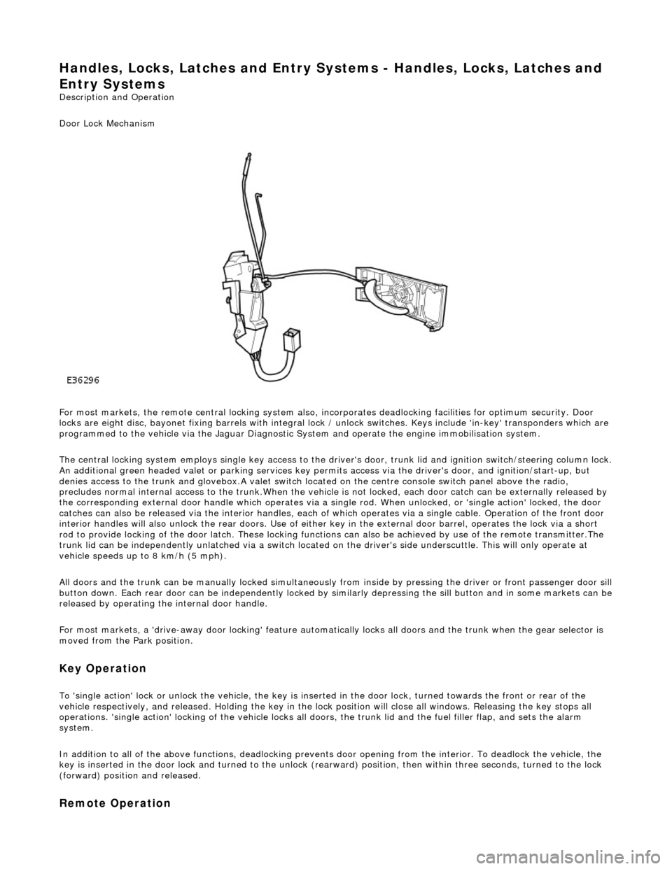
Door Lock Mechanism
For most markets, the remote central locking system also, in corporates deadlocking facilities for optimum security. Door
locks are eight disc, bayonet fixing barrels with integral lock / unlock switches. Keys include 'in-key' transponders which are
programmed to the vehicle via the Jaguar Diagnostic Sy stem and operate the engine immobilisation system.
The central locking system employs single key access to the driv er's door, trunk lid and ignition switch/steering column lock.
An additional green headed valet or park ing services key permits access via the driver's door, and ignition/start-up, but
denies access to the trunk and glovebox.A valet switch located on the centre console switch panel above the radio,
precludes normal internal access to the trunk.When the vehicle is not locked, each door catch can be externally released by
the corresponding external door handle which operates via a si ngle rod. When unlocked, or 'single action' locked, the door
catches can also be released via the interior handles, each of which operates via a single cable. Operation of the front door
interior handles will also unlock the rear doors. Use of either key in the external door barrel, operates the lock via a short
rod to provide locking of the door latch. These locking functions can also be achieved by use of the remote transmitter.The
trunk lid can be independently unlatched via a switch located on the driver's side underscuttle. This will only operate at
vehicle speeds up to 8 km/h (5 mph).
All doors and the trunk can be manually lock ed simultaneously from inside by pressing the driver or front passenger door sill
button down. Each rear door can be independently locked by si milarly depressing the sill button and in some markets can be released by operating the internal door handle.
For most markets, a 'drive-away door locking' feature automati cally locks all doors and the trunk when the gear selector is
moved from the Park position.
Key Operation
To 'single action' lock or unlock the vehicle, the key is inserted in the door lock , turned towards the front or rear of the
vehicle respectively, and released. Holding the key in the lock position will close all windows. Releasing the key stops all
operations. 'single action' locking of the vehicle locks all doors, the trunk lid and the fuel filler flap, and sets the alarm
system.
In addition to all of the above functions, deadlocking prevents door opening from th e interior. To deadlock the vehicle, the
key is inserted in the door lock and turned to the unlock (rearw ard) position, then within three seconds, turned to the lock
(forward) position and released.
Remote Operation
Page 2308 of 2490

The rain sensor unit is installed on the inside of the windshield within the rear view mirror stem cover. The unit is secured t o
the glass by a special adhesive th at facilitates service removal. When installing a rain sensor unit, it must be positioned in
the clear circle within the obscuration band.
The rain sensor control module is a non- serviceable unit installed in the engine bay cool box and connected to the rain
sensor unit and the body processor module.
Page 2322 of 2490
Wipers and Washers - Windshield Wiper/Washer Switch
Removal and Installation
Removal
1. Ensure that steering wheel is in the straight ahead, fully
lowered and fully ex tended position.
2. Remove battery cover and disc onnect ground cable from
battery terminal. Refer to 86.15.19.
3. WARNINGS:
FOLLOWING DISCONNECTION OF THE BATTERY, A PERIOD
OF AT LEAST ONE MINUTE MUST BE ALLOWED TO ELAPSE
BEFORE ANY WORK IS CARRIED OUT ON AN AIR BAG MODULE.
FOLLOWING TEN YEARS IN SERVICE, AN AIR BAG MODULE
MUST BE REMOVED AND DISPOSED OF IN THE APPROVED
MANNER, AND A NEW AIR BAG MUST BE FITTED.
AIR BAGS CONTAIN A CHEMICAL IRRITANT. IF AN AIR BAG
IS RENEWED, THE ORIGINAL UNIT MUST BE DISPOSED OF IN
ACCORDANCE WITH CURRENT SAFETY PROCEDURES.
IN THE EVENT OF A FAULT RUPTURING THE 10A BATTERY
SUPPLY FUSE (F4 LOCATED IN THE FUSE-BOX AT THE DRIVER'S
END OF THE FASCIA), THE FUSE MUST NOT BE RENEWED UNTIL
THE AIRBAG/SRS SYSTEM HAS BEEN DE-ACTIVATED. FUSES OF
ANY OTHER VALUE MUST NEVER BE USED, AS THIS CAN CAUSE
DISARM FAILURE.
Remove driver airbag. Refer to 76.73.39.
4. Remove steeri ng wheel.
5. Remove steering column lowe r cowl. Refer to 76.46.03.
6. Remove steering column upper cowl. Refer to 76.46.02.
7. Remove driver side unders cuttle. Refer to 76.46.11.
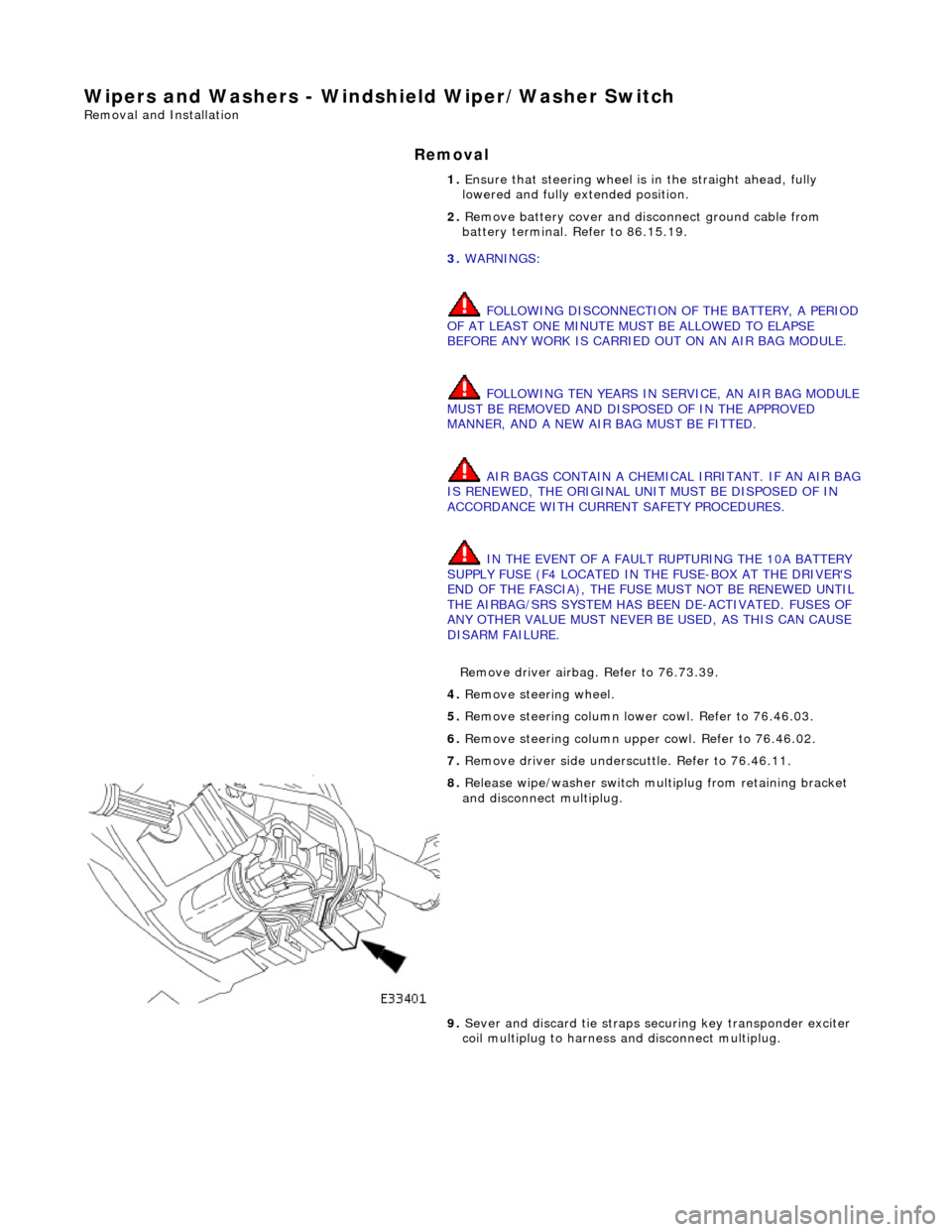
8. Release wipe/washer switch mult iplug from retaining bracket
and disconnect multiplug.
9. Sever and discard tie straps se curing key transponder exciter
coil multiplug to harness and disconnect multiplug.
Page 2362 of 2490
Safety Belt System - Front Safety Belt Retractor
Removal and Installation
Removal
• WARNINGS:
IF A SEAT BELT PRETENSIONING UNIT IS INADVERTENTLY RUPTURED AND INGESTION AND/OR INHALATION
OCCURS, FIRST AID MUST BE APPLIED AND MEDICAL ADVICE SOUGHT.
NO ATTEMPT MUST BE MADE TO DISMANTLE A PRETENSIONING RETRACTOR UNIT. THERE ARE NO SERVICEABLE
PARTS.
WHEN HANDLING A RETRACTOR UNIT PISTON HOUSING, THE PISTON MUST ALWAYS BE POINTED DOWNWARDS
AND AWAY FROM ONE'S SELF AND OTHER PERSONNEL AND FINGERS MUST BE KEPT AWAY FOM THE TAKE-UP SPOOL
MECHANISM.
ANY PRETENSIONING UNIT DROPPED FROM A HEIGHT GREA TER THAN 0.3M (12 INCHES) MUST NOT BE FITTED TO A
VEHICLE.
UNACTIVATED PRE-TENSIONING UNIT COMPONENTS CONTAIN A SOLID, FLAMMABLE MATERIAL.
1. Position seat fully forward for access.
2. Remove battery cover and disc onnect ground cable from
battery terminal. Refer to 86.15.19.
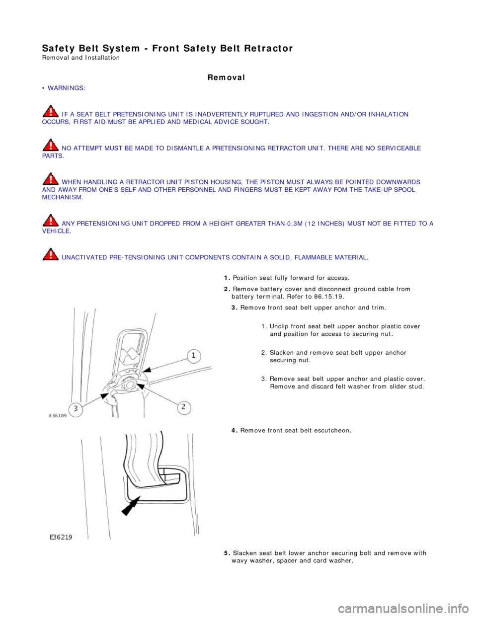
3. Remove front seat belt upper anchor and trim.
1. Unclip front seat belt upper anchor plastic cover
and position for access to securing nut.
2. Slacken and remove se at belt upper anchor
securing nut.
3. Remove seat belt upper anchor and plastic cover. Remove and discard felt washer from slider stud.
4. Remove front seat belt escutcheon.
5. Slacken seat belt lower anchor securing bolt and remove with
wavy washer, spacer and card washer.