width JAGUAR X308 1998 2.G Workshop Manual
[x] Cancel search | Manufacturer: JAGUAR, Model Year: 1998, Model line: X308, Model: JAGUAR X308 1998 2.GPages: 2490, PDF Size: 69.81 MB
Page 47 of 2490
Mem
ory
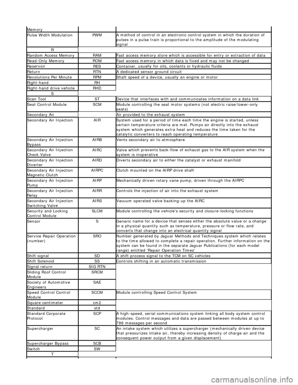
Pulse Width ModulationPW
M
A
method of control in an electronic co
ntrol system in which the duration of
pulses in a pulse train is proportional to the amplitude of the modulating
signal
R
Ran
dom Access Memory
RAMF
ast access memory store which is accessible for entry or extraction of data
Re
ad-Only Memory
RO
M
F
ast access memory in which data
is fixed and may not be changed
Re
servoir
RESContaine
r, usually for oils,
coolants or hydraulic fluids
Re
turn
RTNA
dedicated sensor ground circuit
R
evolutions Per Minute
RP
M
Shaft speed o
f a device, us
ually an engine or motor
R
ight-hand
RH
Right-hand drive veh
icle
RHD
S
Scan T
ool
STDe
vice that interfaces with and comm
unicates information on a data link
Se
at Control Module
SCMModule
controlling the seat motor systems (not electric raise/lower-only
seats)
Secon
dary Air
Air pro
vided to the exhaust system
Secon
dary Air Injection
AIRSy
stem used for a period of time each
time the engine is started, unless
certain temperature criter ia are met. Pumps air directly into the exhaust
system which generates extra heat and reduces the time taken for the
catalytic converters to reach operating temperature
Secon
dary Air Injection
Bypass
AIRBVents secon
dary air to atmosphere
Secon
dary Air Injection
Check Valve
AIRCValve wh
ich prevents back-flow of exhaust gas to the AIR system when the
system is inoperative
Secon
dary Air Injection
Diverter
AIRDD
iverts secondary air to either
the catalyst or exhaust manifold
Secon
dary Air Injection
Magnetic Clutch
AIRP
C
Clu
tch mounted on the AIRP drive shaft
Secon
dary Air Injection
Pump
AIRPMe
chanically driven rotary vane
pump, driven through the AIRPC
Secon
dary Air Injection
Relay
AIRRCont
rols the injection of air into the exhaust system
Secon
dary Air Injection
Switchin
g Va
lve
AIRSV
acuum operated valve backing-up the AIRC
Secu
rity and Locking
Control Module
SLCMModul
e controlling the vehicle's security and closure-locking functions
SensorSGeneri
c name for a device
that senses either the absolute value or a change
in a physical quantity su ch as temperature, pressure or flow rate, and
converts that change into an electrical quantity signal
Servic
e Repair Operation
(number)
SRONu
mber generated by Jaguar Methods
and Techniques system which relates
to the time allowed to complete a repair operation. Further information on the
system can be found in the separate Jaguar Publications (for each model
range) entitled 'Repair Operation Times'
Shif
t signal
SDA
shift process signal to the TCM on SC vehicles
Shif
t Solenoid
SSControls shi
fting in an automatic transmission
Si
gnal return
SIG RTN
Slidin
g Roof Control
Module
SRCM
Society of Automotive
Engineers
SAE
Speed
Control Control
Module
SCCMModule con
trolling Speed Control System
Square c
entimeter
cm
2
Stan
dard
std
Stan
dard Corporate
Protocol
SCPA
high-speed, serial communications system linking all body system control
modules. Control messages and data ar e passed between modules at up to
786 messages per second
SuperchargerSCAn in
take system which utilizes a supercharger (mechanically driven device
that pressurizes intake air, thereby in creasing density of charge air and the
consequent power output from a given displacement)
Supercharger
Bypass
SCB
SwitchSW
T
Page 264 of 2490
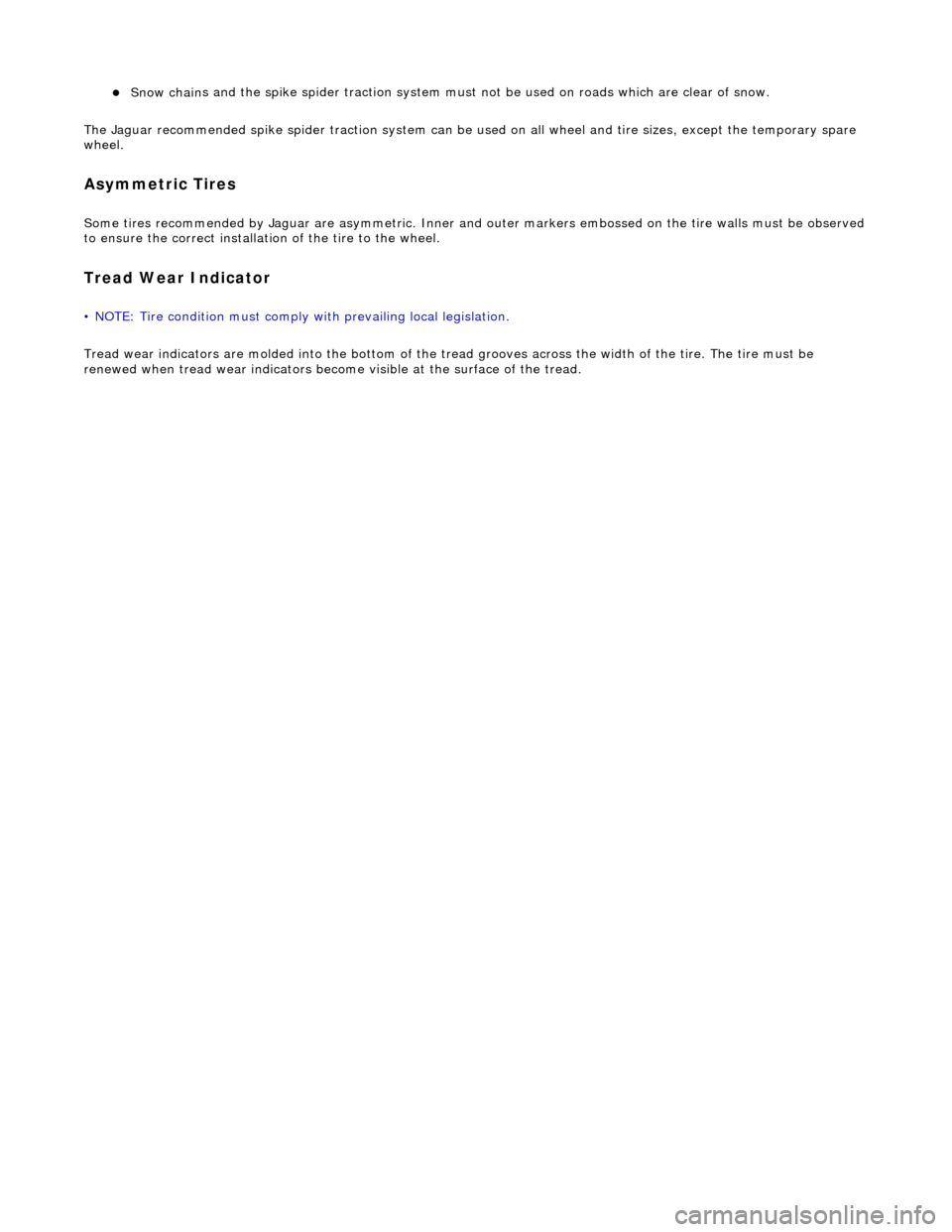
Snow chain
s and the spike spider tr
action system must not be used on roads which are clear of snow.
The Jaguar recommended spike spider tracti on system can be used on all wheel and tire sizes, except the temporary spare
wheel.
Asym metric
Tires
Some
tir
es recommended by Jaguar are as
ymmetric. Inner and outer markers embossed on the tire walls must be observed
to ensure the correct installati on of the tire to the wheel.
Tread We
ar Indicator
• NO
TE: Tire condition must comply with prevailing local legislation.
Tread wear indicators are molded into the bottom of the tr ead grooves across the width of the tire. The tire must be
renewed when tread wear indicators become visible at the surface of the tread.
Page 469 of 2490
Buzz (E
lectrical)
A
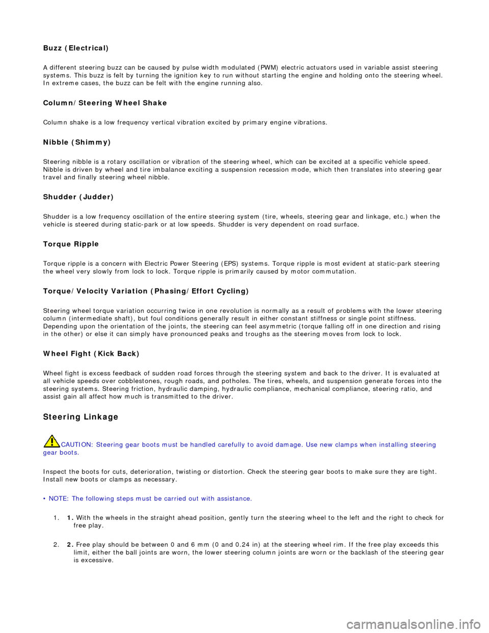
different steering buzz can be caused by
pulse width modulated (PWM) electric actuators used in variable assist steering
systems. This buzz is felt by turning the ignition key to run without starting the engine and holding onto the steering wheel.
In extreme cases, the buzz can be felt with the engine running also.
Column/Steering Wheel
Shake
Column shake is a low f
requenc
y vertical vibration excited by primary engine vibrations.
Nibble (Shimm
y)
Steeri
ng nibble is a rotary oscillation or
vibration of the steering wheel, which can be excited at a specific vehicle speed.
Nibble is driven by wheel and tire imbalance exciting a suspensi on recession mode, which then translates into steering gear
travel and finally steering wheel nibble.
Shudder (Judd
er)
Shudder i
s a low frequency oscillation of th
e entire steering system (tire, wheels, st eering gear and linkage, etc.) when the
vehicle is steered during static-park or at low sp eeds. Shudder is very dependent on road surface.
Torque Ri
pple
Torque rippl
e is a concern with Electric Power Steering (EPS) sy
stems. Torque ripple is most evident at static-park steering
the wheel very slowly from lock to lock. Torque ripple is primarily caused by motor commutation.
Torque/Veloc
ity Variation
(Phasing/Effort Cycling)
Steeri
ng wheel torque variation oc
curring twice in one revolution is normally as a result of problems with the lower steering
column (intermediate shaft), but foul cond itions generally result in either constant stiffnes s or single point stiffness.
Depending upon the orientation of the joints, the steering can fe el asymmetric (torque falling off in one direction and rising
in the other) or else it can simply have pronounced peaks and troughs as the steering moves from lock to lock.
Wheel Fight
(Kick Back)
W
heel fight is excess feedback of sudden road forces through th
e steering system and back to the driver. It is evaluated at
all vehicle speeds over cobblestones, rough roads, and potholes . The tires, wheels, and suspension generate forces into the
steering systems. Steering friction, hydraulic damping, hydr aulic compliance, mechanical compliance, steering ratio, and
assist gain all affect how much is transmitted to the driver.
Stee
ring Linkage
CAUTI
ON: Steering gear boots must be
handled carefully to avoid damage. Use new clamps when installing steering
gear boots.
Inspect the boots for cuts, deterioration, tw isting or distortion. Check the steering gear boots to make sure they are tight.
Install new boots or clamps as necessary.
• NOTE: The following steps must be carried out with assistance.
1. 1. With the wheels in the straight ahead po sition, gently turn the steering wheel to the left and the right to check for
free play.
2. 2. Free play should be between 0 and 6 mm (0 and 0.24 in) at the steering wheel rim. If the free play exceeds this
limit, either the ball joints are worn, the lower steering column joints are worn or the backlash of the steering gear
is excessive.
Page 1149 of 2490
The E
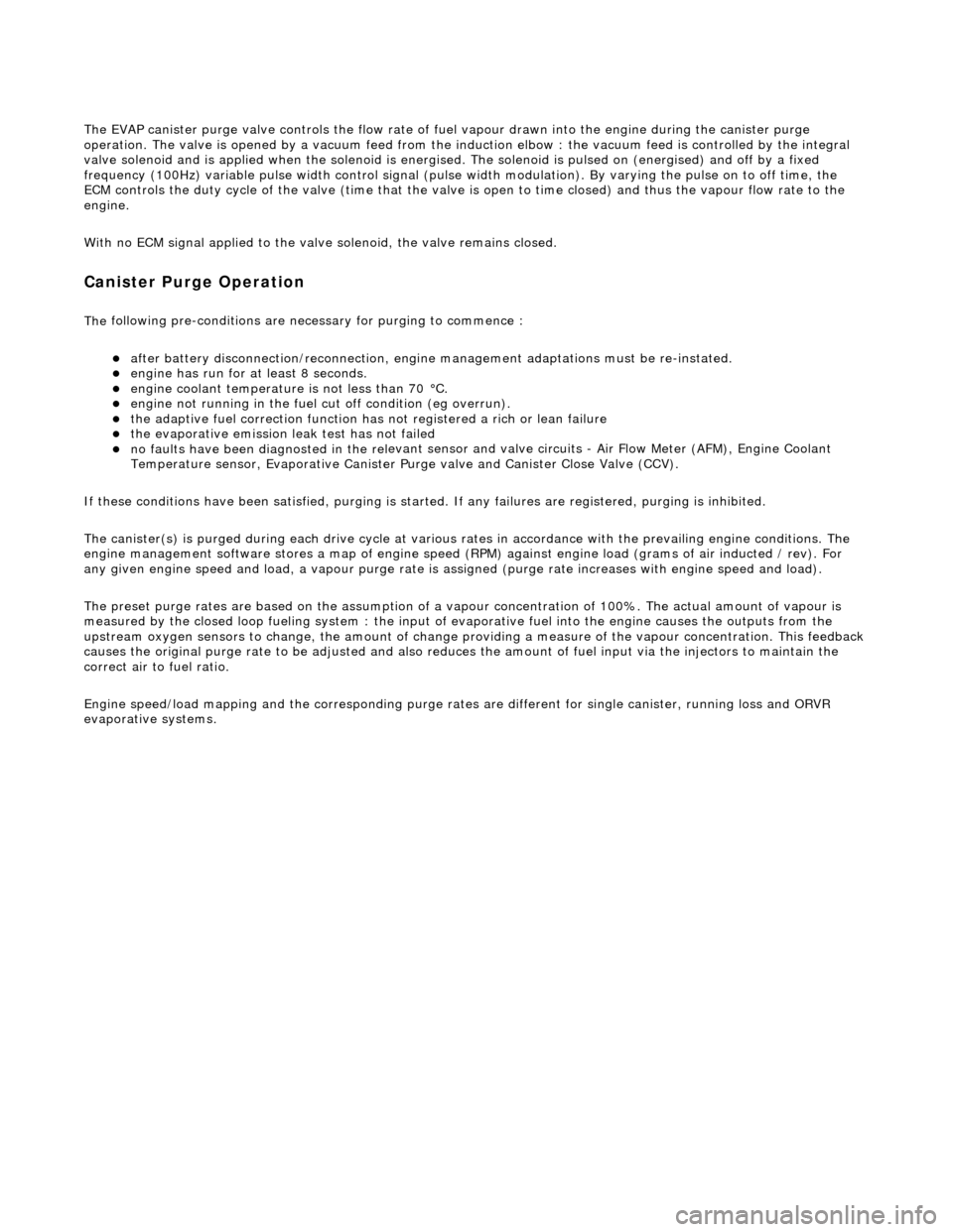
VAP canister purge valve controls th
e flow rate of fuel vapour drawn into the engine during the canister purge
operation. The valve is opened by a vacu um feed from the induction elbow : the vacu um feed is controlled by the integral
valve solenoid and is applied when the so lenoid is energised. The solenoid is pulsed on (energised) and off by a fixed
frequency (100Hz) variable pulse width control signal (pulse width modulation). By varying the pulse on to off time, the
ECM controls the duty cycle of the valve (time that the valve is open to time closed) and thus the vapour flow rate to the
engine.
With no ECM signal applied to the va lve solenoid, the valve remains closed.
Can
ister Purge Operation
The
following pre-conditions are ne
cessary for purging to commence :
aft
er battery disconnection/reconnection, engine
management adaptations must be re-instated.
engine has run for
at least 8 seconds.
engi
ne coolant temperature is not less than 70 °C.
engine
not running in the fuel
cut off condition (eg overrun).
t
he adaptive fuel correction
function has not registered a rich or lean failure
t
he evaporative emission leak test has not failed
no faults have been diagnosted in th
e rel
evant sensor and valve circuits -
Air Flow Meter (AFM), Engine Coolant
Temperature sensor, Evaporativ e Canister Purge valve and Canister Close Valve (CCV).
If these conditions have been satisfied, purging is started. If any failures are registered, purging is inhibited.
The canister(s) is purged during each driv e cycle at various rates in accordance with the prevailing engine conditions. The
engine management software st ores a map of engine speed (RPM) against engine load (grams of air inducted / rev). For
any given engine speed and load, a vapour purge rate is assigned (purge rate increases with engine speed and load).
The preset purge rates are base d on the assumption of a vapour concentratio n of 100%. The actual amount of vapour is
measured by the closed loop fueling system : the input of evaporative fuel into the engine causes the outputs from the
upstream oxygen sensors to change, the am ount of change providing a measure of the vapour concentration. This feedback
causes the original purge rate to be adju sted and also reduces the amount of fuel input via the injectors to maintain the
correct air to fuel ratio.
Engine speed/load mapping and the corresp onding purge rates are different for single canister, running loss and ORVR
evaporative systems.
Page 1263 of 2490
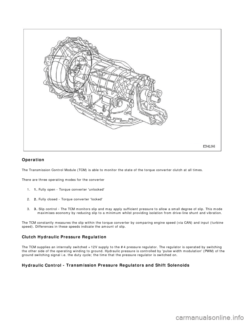
Op
eration
The T
ransmission Control Module (TCM) is
able to monitor the state of the torque converter clut ch at all times.
There are three operating modes for the converter
1. 1. Fully open - Torque converter 'unlocked'
2. 2. Fully closed - Torque converter 'locked'
3. 3. Slip control - The TCM monitors slip and may apply sufficie nt pressure to allow a small degree of slip. This mode
maximises economy by reducing slip to a minimum whilst providing isolation from drive-line shunt and vibration.
The TCM constantly measures the slip within the torque conver ter by comparing engine speed (via CAN) and input (turbine
speed). Differences in these speeds indicate the amount of slip.
Clutch Hydraulic Pressure Regulation
The T
CM supplies an internally switched +1
2V supply to the #4 pressure regulator. The regulator is operated by switching
the other side of the operating winding to ground. Hydraulic pressure is controlled by 'pulse width modulation' (PWM) of the
ground switching signal i.e. the duty cycle; the time that the pressure regulator is switched on.
Hydraulic Control
- Transmission Pre
ssure Regulators an d Shift Solenoids
Page 1264 of 2490
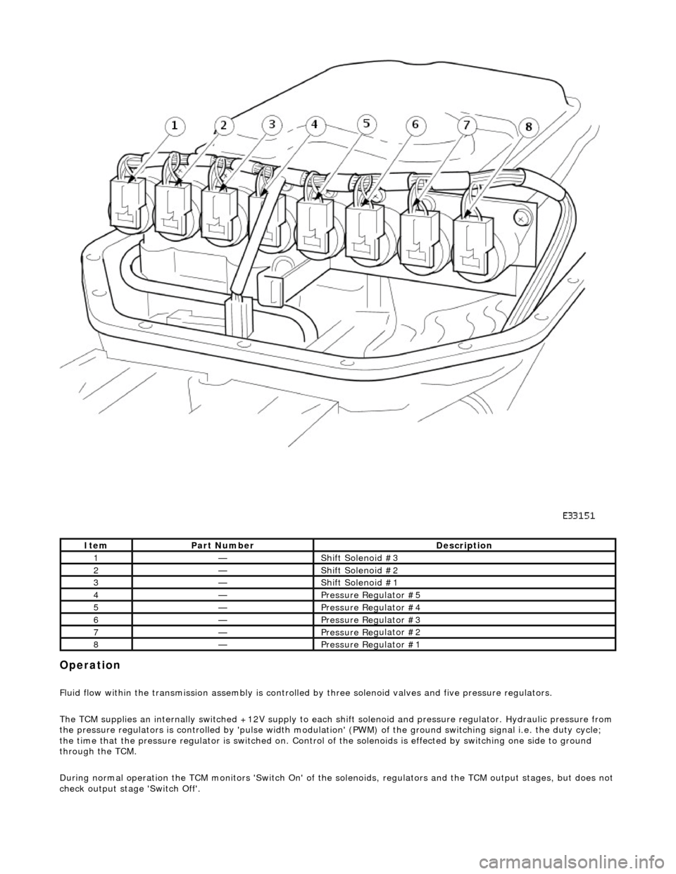
Opera
tion
F
l
uid flow within the transmission assembly is controlled
by three solenoid valves and five pressure regulators.
The TCM supplies an internally switched +12V supply to each sh ift solenoid and pressure regulator. Hydraulic pressure from
the pressure regulators is controlled by 'pulse width modulation' (PWM) of the ground switching signal i.e. the duty cycle;
the time that the pressure regu lator is switched on. Control of the solenoids is effected by switching one side to ground
through the TCM.
During normal operation the TCM monitors 'Switch On' of the so lenoids, regulators and the TCM output stages, but does not
check output stage 'Switch Off'.
It e
m
Par
t
Number
De
scr
iption
1—Shif
t Sole
noid #3
2—Shif
t Sole
noid #2
3—Shif
t Sole
noid #1
4—Pressure R
e
gulator #5
5—Pressure R
e
gulator #4
6—Pressure R
e
gulator #3
7—Pressure R
e
gulator #2
8—Pressure R
e
gulator #1
Page 1265 of 2490
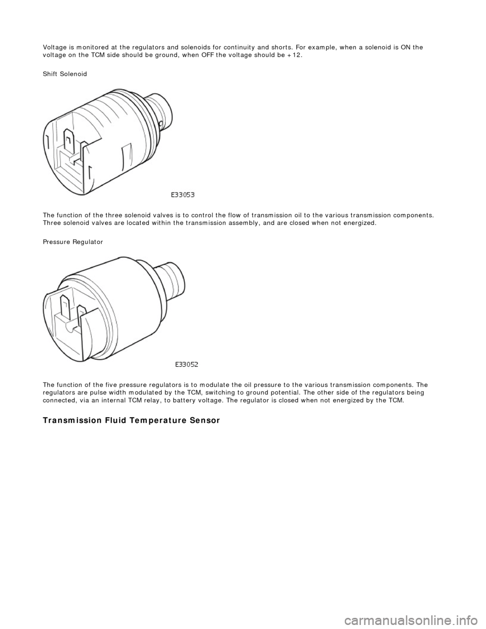
Voltage is monitored at the regulators and solenoids for continuity and shorts. For example, when a solenoid is ON the
voltage on the TCM side should be ground , when OFF the voltage should be +12.
Shift Solenoid
The function of the three soleno id valves is to control the flow of transmissi on oil to the various transmission components.
Three solenoid valves are located wi thin the transmission assembly, and are closed when not energized.
Pressure Regulator
The function of the five pressu re regulators is to modulate the oil pressure to the various transmission components. The
regulators are pulse width modulated by the TCM, switching to ground potential. The other side of the regulators being
connected, via an internal TCM relay, to battery voltage. The regulator is closed when not energized by the TCM.
Transmission Fluid Temperature Sensor
Page 1869 of 2490
The functi
on of the parking aid is to prov
ide an audible warning to the driver of the distance to obstacles near the rear
bumper of the vehicle when parking or travelling at a slow sp eed. The system provides an assistance to the driver when
parking in order to help avoid collision with obstacles.
The sensor range at the rear of the vehicl e should be 1.8 meters. This should extend the full width of the rear bumper and
reduce to 50 cm at the vehicle co rners. The vertical range is adequate to protec t the highest and lowest points of the rear of
the vehicle. The system will detect curbs with heights of at least 18 cm. Obstacles, such as curbs, that are low enough to
pass under the vehicle until they make contact with the tires will not be detected.
The system activates a specific speaker with a tone signifying the distance to the obstacle. The tone consists of a beep and
defined space ratio which varies depending on the calculated distance. When the distance to the obstacle is less than 20 cm
the speaker tone is continuous.
The parking aid is continuously in operation, unless towing wh en the system automatically switches off. If the reverse aid
develops a fault the tone will sound continuously for three seconds when the igni tion is switched on or the reverse gear is
selected.
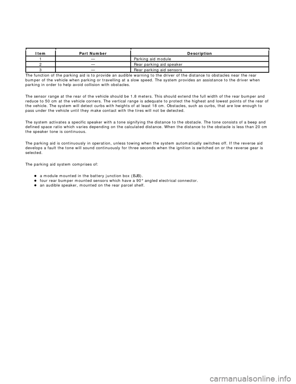
The parking aid system comprises of:
a
module mounted in the batte
ry junction box (BJB).
fou
r rear bumper mounted sensors which have a 90° angled electrical connector.
an audible speaker, moun
ted on
the rear parcel shelf.
It
em
Par
t Number
De
scription
1—Parkin
g aid module
2—Rear
parking aid speaker
3—Rear
parking aid sensors
Page 2022 of 2490
Body closures
Each front and rear door consists of a welded, mild steel inner frame and an outer panel. The outer panel is welded to the
waist rail and cheater of the inner frame, then bonded and clinched to fo rm the door assembly. Cosmetic PVC bead is
applied to all clinch joints. Sp onge rubber seals are mounted on the doors. Inte rnal insulation is provided by a foam water
shedder attached to the door by double-sided adhesive tape.
The door aperture B/C posts are reinforced over their full height to fully satisfy all forthcoming European and Federal side
impact legislation. The hood consists of one piece inner and outer panels clinched and bonded together, with cosmetic bead
PVC sealant applied to all clinch joints. Th e hood pivots at the front on two hinges each secured by bolts to the hood front
underside and the BIW front upper crossmem ber. Two gas struts secured to the hood by pivot pins and snap-on couplings,
support the hood in the open position. A full width insulating pad is secured by screws to the underside of the hood. A
sponge rubber tubular seal is mounted tran sversely towards the front of the hood underside. The trunk lid is of similar
construction to the hood, consisting of inner and outer pa nels clinched and bonded together and PVC bead sealed.
Incorporating a removable moulded liner and two trunk illuminati on lights, the trunk lid is supported when open, by two gas
struts, each secured to the inner wheel arch and trunk hinge by snap fittin gs. For some markets, a warning triangle is
attached to a bracket on the trunk lid underside and is retained in the open position by a rubber block.
Fascia
One-piece slush-moulded fascia on inject ion moulded armature and steel cross-rail reinforcement. Fascia support brackets
set with BIW to achieve close tolerance fit of fascia to bo dy eliminate necessity for adjustment following removal and
installation..
Fuel Filler Flap
The fuel filler comprising a hinged flap attached to the body decking panel by tw o nuts, incorporates a rubber buffer, snap-
in striker, hinge spring and fuel cap stowage magnet. The rubber fuel bowl moulding is attached via a steel armature to the
body reinforcement panel by five M5 nuts and is retained at the filler neck by a clip. The mating drain tube is fitted with an
internal filter. The fuel filler flap latch mechanism attached to the fuel bowl armatu re by two M5 nuts, includes a locking pin
and actuator which are both se rviceable items. The latch actuator operates independently from the central locking system;
it is driven directly by the se curity and locking control module. Locking of the fuel filler flap is achi eved only by operation of
the key or by the remote rf transmitter.
Seating
All front seats are equipped with electric height adjustment. In addition, both seats are available with manual or power
forward and rearward adjustment, manual or power operated headrest adjustment, 12 way electric adjustment, memory
controlled 12 way seat adjustment and integral seat heating. A side air bag module is installe d in the outboard squab wing
of each front seat. Each front seat has a non-handed, one-piece frame incorporatin g cushion and squab frames, side air bag
support bracket and seat adjuster mechanis ms. Seat switchpacks are installed on the outboard side of driver and passenger
seats and control modules are installed in the base of each seat . The standard rear seat is of fixed, bench type with full
width removable cushion. For certain mark ets, two individual rear seats are available as an option on long wheelbase
models. Both type s of rear seat are available with th ermostatically controlled heating of the cushion and sq uab. Individual
rear seats are electrically adjustable fo r squab re cline (via cushion fore and af t movement), head restraint height and
lumbar support. Separate motors provide ad justment of each seat cushion and head restraint and an electrically driven air
compressor provides variation of lumbar support. Seat adjustment is controlled via switches installed on a panel in an
extension to the centre console.Both the driver and front pass enger seat are secured to the vehicle floor at four points.
Interior Trim
The one-piece door casings are trimmed in UEV to match the seating, with wood veneer at the waistline and a carpet insert
at the front lower corner. Each casing is secured to the door inner panel by fir tree fastener s along the lower section, two
armrest fixings at the centre and veneer panel dowels and fixings at the top. The armrests which are common to front and
rear doors, are trimmed in matc hing leather or UEV according to specification. Switchpacks dedicated to driver and front or
rear passenger, are incorporated in the ar mrests. A speaker is installed in the lower section of each door and a tweeter is
incorporated behind each interior door handle escutcheon. where premium ICE is fitted, the front tweeters are installed in
the upper A posts. On each side, a graine d UEV finisher trimmed to match the head lining is secured to the 'A' post and
cantrail by fir tree fasteners locating in BIW apertures. Th e upper 'D' post finisher is trimmed and secured in the same
manner. The single piece'B' post finishers, also finished in grained matching UEV, each have a front seat belt exit aperture
and are secured to the BIW by four spring clips and two fir tree fasteners. The one-piece headlining consists of a 6mm thick
polyurethane foam membrane covered with suede effect knitted polyester. The headlining is secured to the BIW roof by
body tangs, the roof console, sun visors, combined grab handles and coat hooks, th e cantrail finishers and where fitted, the
Page 2035 of 2490
the BIW front upper crossmember. Two gas struts secured to the hood by pi vot pins and snap-on couplings, support the
hood in the open position. A full width insulating pad is secured by screws to the underside of the hood. A sponge rubber
tubular seal is mounted transversely to wards the front of the hood underside.
Trunk
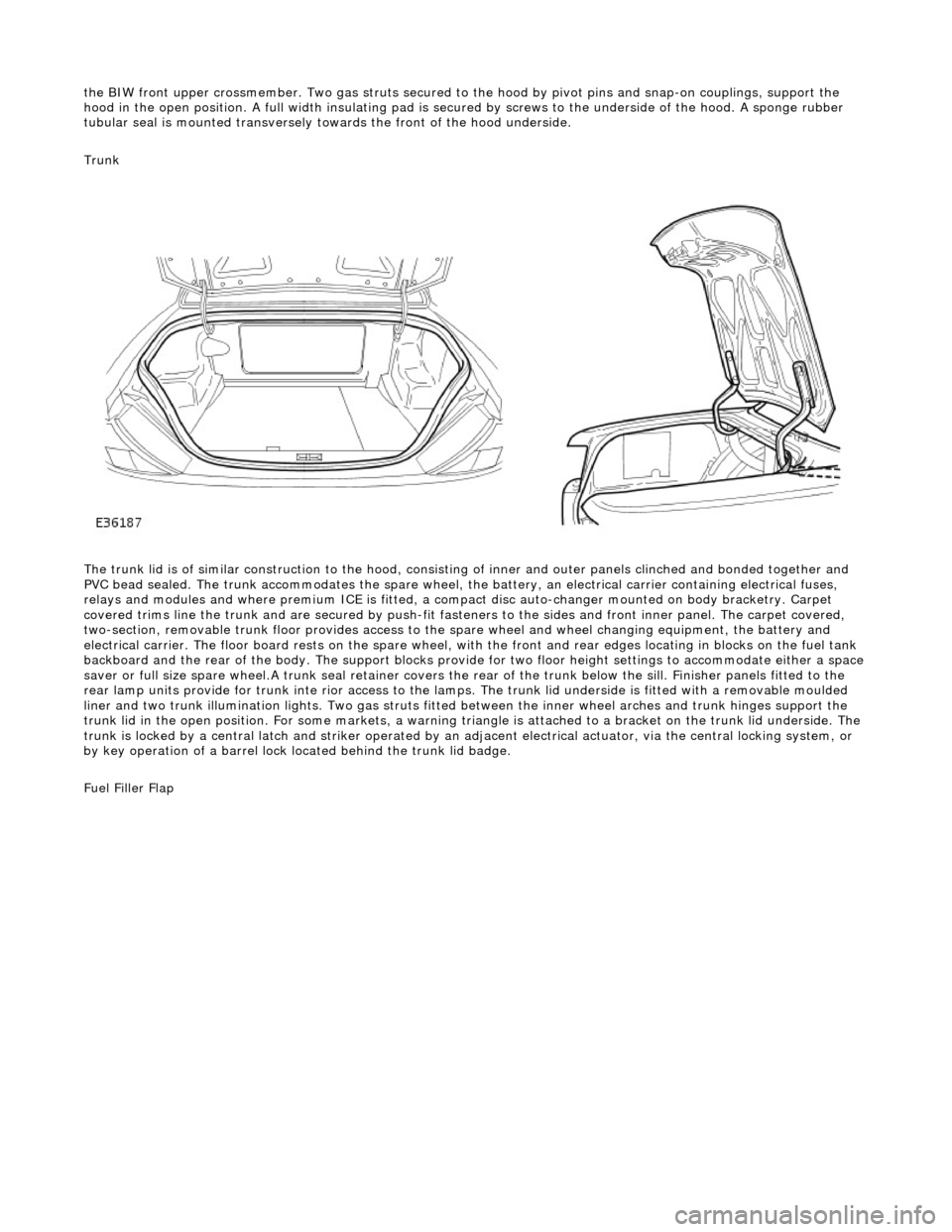
The trunk lid is of similar construction to the hood, consisting of inner and outer panels clinched and bonded together and
PVC bead sealed. The trunk accommodates the spare wheel, the battery, an electrical carrier containing electrical fuses,
relays and modules and where premium ICE is fitted, a compac t disc auto-changer mounted on body bracketry. Carpet
covered trims line the trunk and are secured by push-fit fasten ers to the sides and front inner panel. The carpet covered,
two-section, removable trunk floor prov ides access to the spare wheel and wheel changing equipment, the battery and
electrical carrier. The floor board rests on the spare wheel, with the front and rear e dges locating in blocks on the fuel tank
backboard and the rear of the body. The support blocks provide for two floor height settings to accommodate either a space
saver or full size spare wheel.A trunk seal retainer covers the re ar of the trunk below the sill. Finisher panels fitted to the
rear lamp units provide for trunk inte rior access to the lamps. The trunk lid underside is fitted with a removable moulded
liner and two trunk illumination lights. Two gas struts fitted between the inner wheel arches and trunk hinges support the
trunk lid in the open position. For some markets, a warning triangle is attached to a bracket on the trunk lid underside. The
trunk is locked by a central latch and stri ker operated by an adjacent electrical actuator, via the central locking system, or
by key operation of a barrel lock located behind the trunk lid badge.
Fuel Filler Flap