Adaptive JAGUAR X308 1998 2.G User Guide
[x] Cancel search | Manufacturer: JAGUAR, Model Year: 1998, Model line: X308, Model: JAGUAR X308 1998 2.GPages: 2490, PDF Size: 69.81 MB
Page 187 of 2490

8. Position the shock absorber and spri
ng assembly to the
vehicle.
9. W
ith assistance, manually re
tract the shock absorber and
remove the temporary securing bolt.
10
.
Remove the special tools 204-179-1.
11
.
Align the shock absorber lower bush to the wishbone and
install the mounting bolt.
1. Install but do not tighten the nut.
12. CAUTION: Make sure the adaptive damping electrical
connector is correctly aligned. Failu re to follow these instructions
may cause damage to the electrical connector.
On vehicles with adaptive damping:
Page 188 of 2490
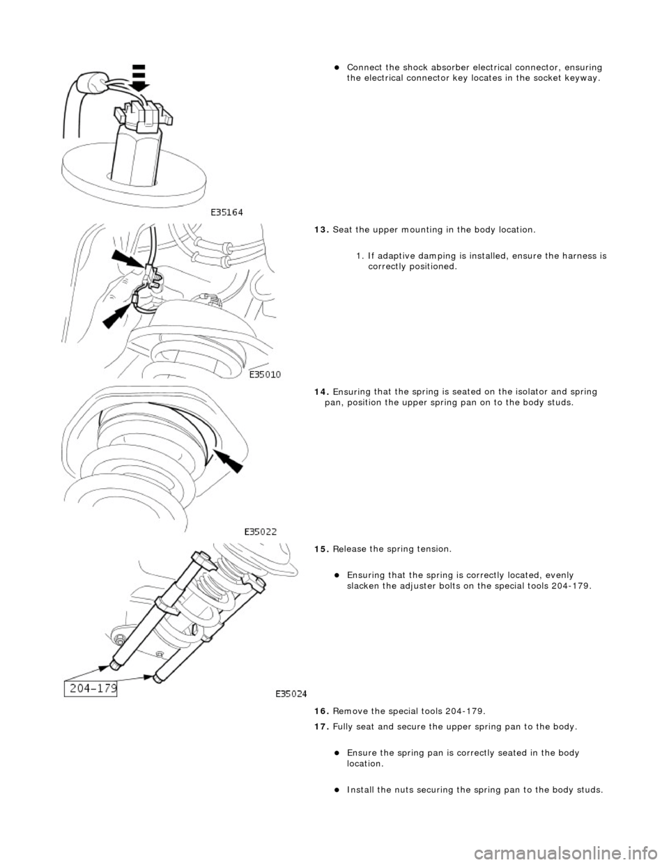
Connect
the shock absorber elec
trical connector, ensuring
the electrical connector key locates in the socket keyway.
13. Seat
the upper mounting in the body location.
1. If adaptive damping is installed, ensure the harness is
correctly positioned.
14 . Ensuri
ng that the spri
ng is seated on the isolator and spring
pan, position the u pper spring pan on to the body studs.
15 . Re
lease the spring tension.
Ensuri
ng that the spri
ng is
correctly located, evenly
slacken the adjuster bolts on the special tools 204-179.
16. Remove the special tools 204-179.
17. Fully seat and secure the u pper spring pan to the body.
Ensure the spring pan i
s correctly seated in the body
location.
Inst al
l the nuts securing the sp
ring pan to the body studs.
Page 198 of 2490

13. U
sing the special tools 204-179-1, secure the upper mounting
to the spring.
14 . Using a jack, retract the sho
ck absorber through the
wishbone aperture.
15 . Posi
tion a bolt through the spring coils and shock absorber
lower-bush, to temporarily locate the shock absorber.
16. Partially lower the jack for a ccess to the top of the shock
absorber.
17. On vehicles with adaptive damping:
Disc
onnect the shock absorber electrical connector by
pressing the lugs down and pulling the connector up.
Page 199 of 2490

18
.
Lower and remove the jack.
19. Remove the shock absorber an d spring assembly from the
vehicle and place the assembly on a work bench.
20. Clean the upper mounting spring location.
21
.
Remove the pigtail seat and cl ean the wishbone lower spring
location.
22
.
With assistance, manually compress the shock absorber and
withdraw the bolt from the spring coils.
23
.
Remove the shock absorber from the upper mounting.
Posi
tion a wrench on the shock absorber shaft flats to
prevent rotation (wrench in socket on vehicles with
adaptive damping).
R
emove the shock absorber
upper retaining nut.
Remove the
upper washer and isolator.
24. Remove the special tools 204-179-1 and remove the upper
mounting from the spring.
Page 203 of 2490
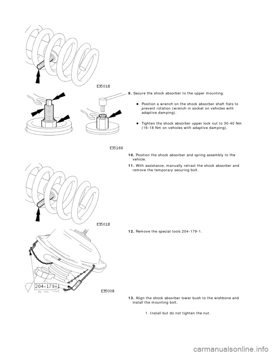
9. Se
cure the shock absorber
to the upper mounting.
Posi
tion a wrench on the shock absorber shaft flats to
prevent rotation (wrench in socket on vehicles with
adaptive damping).
Tigh
ten the shock absorber upper lock nut to 30-40 Nm
(16-18 Nm on vehicles with adaptive damping).
10. Position the shock absorber and spring assembly to the
vehicle.
11
.
With assistance, manually re tract the shock absorber and
remove the temporary securing bolt.
12
.
Remove the special tools 204-179-1.
13. Align the shock absorber lower bush to the wishbone and
install the mounting bolt.
1. Install but do not tighten the nut.
Page 204 of 2490
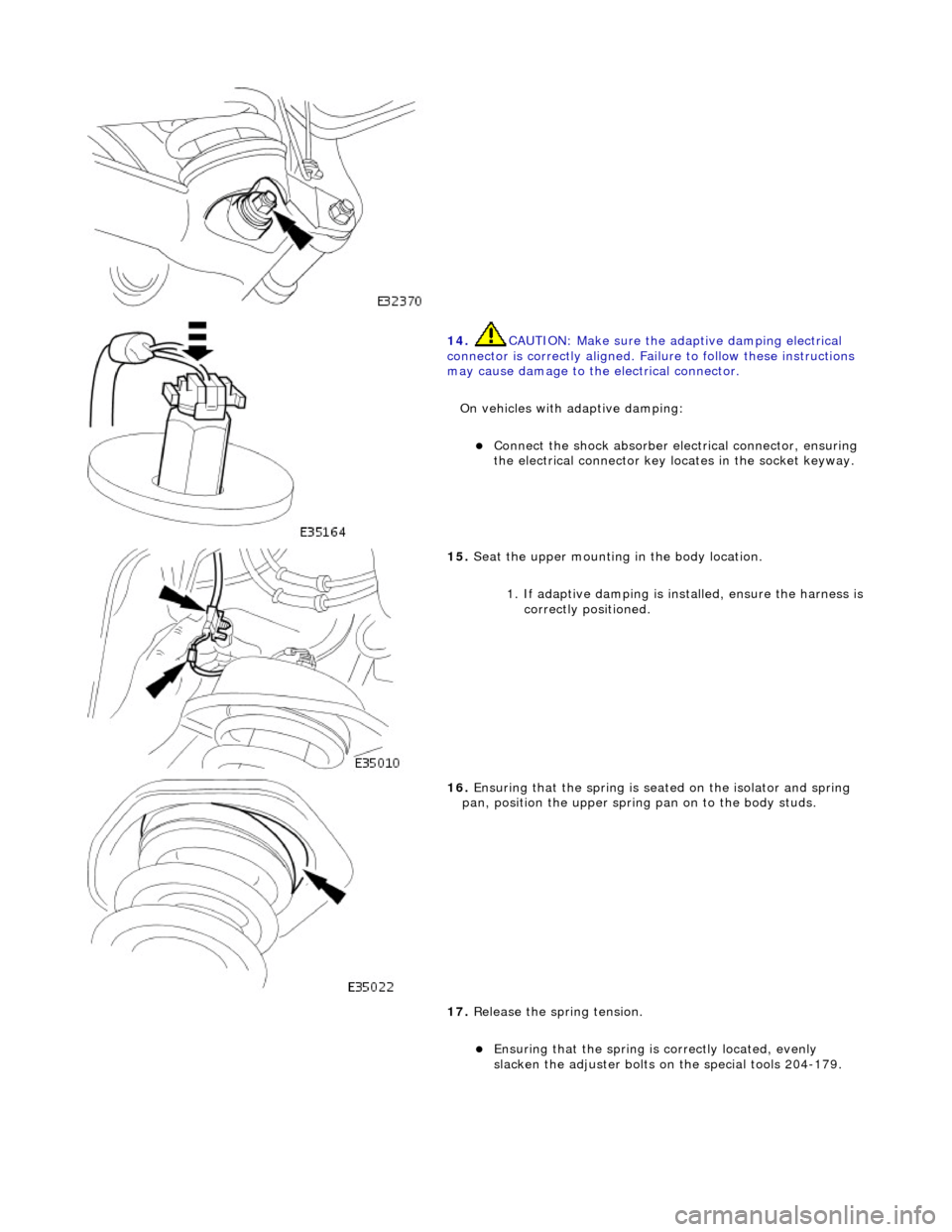
14. CAUTI
ON: Make sure the adaptive damping electrical
connector is correctly aligned. Failu re to follow these instructions
may cause damage to the electrical connector.
On vehicles with adaptive damping:
Conne ct
the shock absorber elec
trical connector, ensuring
the electrical connector key locates in the socket keyway.
15 . Seat
the upper mounting in the body location.
1. If adaptive damping is installed, ensure the harness is
correctly positioned.
16 . Ensuri
ng that the spri
ng is seated on the isolator and spring
pan, position the u pper spring pan on to the body studs.
17. Release the spring tension.
Ensuring that the spri
ng is
correctly located, evenly
slacken the adjuster bolts on the special tools 204-179.
Page 273 of 2490
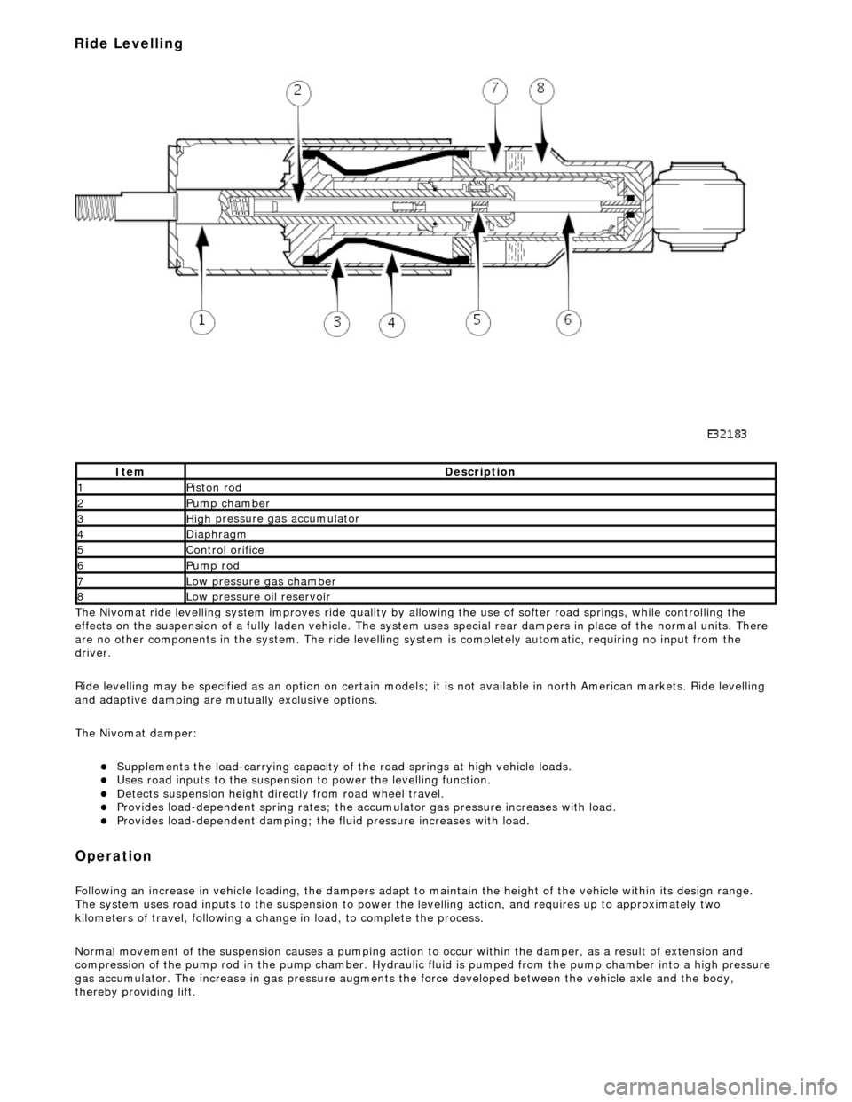
The
Nivomat ride levelling system improves ride quality by al
lowing the use of softer road springs, while controlling the
effects on the suspension of a fully laden vehicle. The system uses special rear dampers in place of the normal units. There
are no other components in th e system. The ride levelling system is comple tely automatic, requiring no input from the
driver.
Ride levelling may be specified as an opti on on certain models; it is not available in north American markets. Ride levelling
and adaptive damping are mu tually exclusive options.
The Nivomat damper:
Su
pplements the load-carrying capacity of th
e road springs at high vehicle loads.
Uses road inputs to the
suspension to power the levelling function.
De
tects suspension height dire
ctly from road wheel travel.
Provi
des load-dependent spring rates; the ac
cumulator gas pressure increases with load.
Pr
ovides load-dependent damping; the fluid pressure increases with load.
Op
eration
F
ollowing an increase in vehicle loading,
the dampers adapt to maintain the height of the vehicle within its design range.
The system uses road inputs to the suspension to power the levelling action, and requires up to approximately two
kilometers of travel, following a change in load, to complete the process.
Normal movement of the suspension caus es a pumping action to occur within the damper, as a result of extension and
compression of the pump rod in the pump chamber. Hydraulic fluid is pumped from the pump cham ber into a high pressure
gas accumulator. The increase in gas pressure augments the force developed between th e vehicle axle and the body,
thereby providing lift.
It
em
De
scription
1Pi
ston rod
2Pum
p chamber
3High
pressure
gas accumulator
4Diaphragm
5Co
ntrol orifice
6Pump rod
7Low pressure gas ch
amber
8Low pressure oil
reservoir
Ride Levelling
Page 274 of 2490
A c
ontrol orifice in the pump rod determines the levelling height. When the damper is compressed, this orifice is covered.
When the damper extends, the control orif ice is uncovered, pressure is released to the low pressure oil reservoir and the
system ceases to rise. When the vehicle is high after unloading, the opened control or ifice allows fluid to be returned to the
low pressure oil reservoir, and the suspensi on returns to its normal unladen height.
Ad
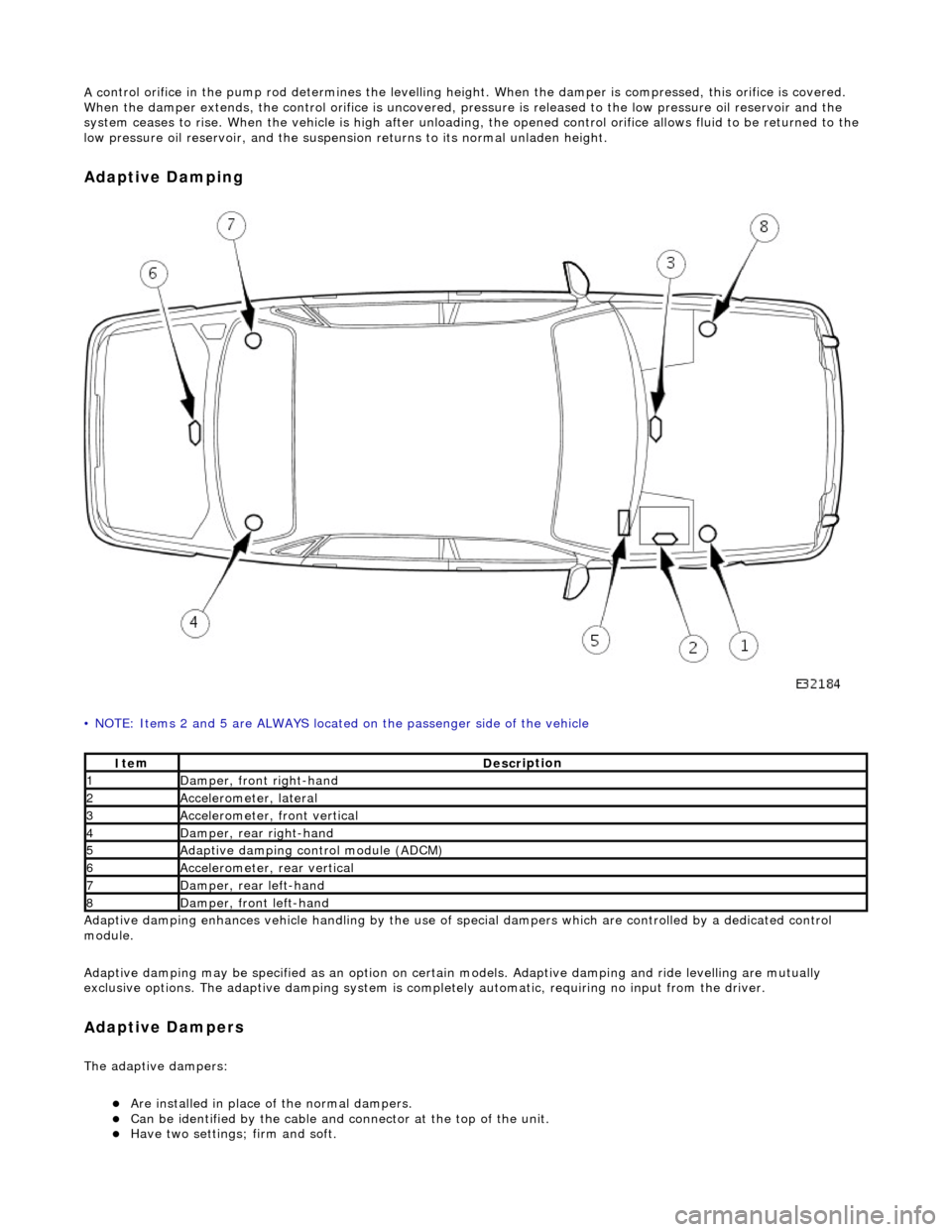
aptive Damping
•
NOTE: Items 2 and 5 are ALWAYS located
on the passenger side of the vehicle
Adaptive damping enhances vehicle handli ng by the use of special dampers which are controlled by a dedicated control
module.
Adaptive damping may be specified as an option on certai n models. Adaptive damping and ride levelling are mutually
exclusive options. The adaptive damping system is completely automatic, requiring no input from the driver.
A d
aptive Dampers
The adaptiv
e dampers:
Are inst
alled in place of the normal dampers.
Can be identified
by the cable and connector at the top of the unit.
Have two settings; fi
rm and so
ft.
It
e
m
De
scr
iption
1Dam
p
er, front right-hand
2Accel
e
rometer, lateral
3Accel
e
rometer,
front vertical
4D
a
mper, rear right-hand
5Adaptive dampin
g control module (A
DCM)
6Accel
e
rometer, rear vertical
7D
amper, rear l
eft-hand
8Dam
p
er, front left-hand
Page 278 of 2490
Vehicle Dynamic Suspension - Vehicle Dynamic Suspension
Diagn
osis and Testing
Refer to the PDU User Guide for details of diagnosing and testing the Adaptive Damping System. The PDU interrogates the
ADCM directly via the K and L lines to the J1962 diagnostic socket.
The PDU will give an indication of the integrity of each electron ic and electrical component. It will indicate, for example, that
the accelerometers are not broken, but not that they functionin g correctly when the vehicle is in motion. However, it is
exceptional for an accelero meter to function incorrectly in its dynamic mode if it is proved to be functioning when static.
Basic Checks
The accele
rometers have the following ch
aracteristics. At 0g (no movement of the body) each vertical accelerometer
outputs approximately 2.5V steady voltage; the lateral acce lerometer outputs approximately 1.5V. The voltage output due
to body movement is proportional to acceleration in the acceleration axis, up to approximately 4.5V and down to
approximately 0.5V.
Before changing any component, refer to the circuit diagrams and check the cont inuity of relevant harness circuits; in some
instances, the PDU will not different iate between a faulty component an d a damaged connection or wiring.
Check the following fuses:
En
gine compartment fuse
box, fuse F5 (10A).
Engine m
anagement fuse
box, fuse F1 (20A).
Check the following ADCM input/output lines:
Sy stem erro
r output from the ADCM
to the instrument cluster.
Vehicl
e speed output from the inst
rument cluster to the ADCM.
Foo
tbrake signal to the ADCM.
Check any relevant connections to confirm that the connection is electrically sound and that a terminal pin has not been
pushed back into the connector shell, ie. not ma king a connection to its mating pin or socket.
Page 522 of 2490
diverter val
ve (if fitted) and oil filter.
Main
bearings
which are grooved in the upper positions and plain in
the lower positions. They are manufactured from
aluminium / tin material.
A c
rankshaft with under
cuts and rolled fillets for extra strength.
Fracture
-split connecting rods in sintered-forged steel.
Brackets
bolted to the front of
the cylinder
block are used to mo unt all accessories.
A sin
gle, seven ribbed vee belt
drives the accessories.
An au
tomatic belt tensioner for the front accessory drive,
incorporating a wear indicator.
An advanced en
gine management system inco
rporating electronic throttle control.
The un
it meets the requirements of the CARB OBDII USA legislation.
Ancillary Systems
The an
ci
llary systems, driven by the engine, each have a
detailed Description and Operation along with Diagnostic
Procedures, and Removal and Installation instructions ; refer to the following sections of this manual:
Power Steeri
ng Pump - Section 211-02
Ai
r Conditioning Compressor - Sectio
n 412-03
Engine
C
ooling Pump - Section 303-03
Generator
- Sectio
n 414-02
The drive belt, idler pulley and automatic tensioner are described in Section 303-05.
The engine starting system is described in Section 303-06.
En
gine Management and Emission Control System
Engine Control Modu
le (ECM)
Engine
management and exhaust emissions are controlled by the ECM, which has the
following main functions:
Fu
el injection
Idle
s
peed
Ignition Ev
aporative loss system
Engine
cooling fans Clim
ate control compressor clutch demand
The microprocessor within the ECM receiv es signals from various sensors and other modules and uses a pre-determined
program to compute engine management functions.
Adaptive functions are incorporated in the ECM to cater for co ntinuous adjustments to its computations to suit prevailing
conditions. Because the system also controls emissions to suit all modes, neither CO levels nor idle speed require service
attention or adjustment, except if an error should occur.
On Board Diagnostics are controlled by the ECM with the continuous monitoring of incoming signals and the subsequent
verification against what the module expects to 'see'. Should a si gnal be incorrect or missing, the ECM will substitute a fixed
value to provide the 'limp home mode' and alert the driver of the problem. Fixed values may be adopted for:
Transmission oil
temperature
Mechanica
l
guar
d position
Throttle blade angle Camshaft position
Inta
k
e air temperature
Diagnostic trouble codes (DTC), including OBD II codes, are stored in the ECM memo ry and can be read by an appropriate
retrieval tool.
Should either the ECM or TCM fa il, ensure that the control housing cooling fan is operating correctly. Failure of the cooling
fan MUST be rectified before renewing a control module and details of a fa n failure should accompany a returned control
module.