drain bolt JAGUAR X308 1998 2.G Workshop Manual
[x] Cancel search | Manufacturer: JAGUAR, Model Year: 1998, Model line: X308, Model: JAGUAR X308 1998 2.GPages: 2490, PDF Size: 69.81 MB
Page 218 of 2490

Rear Suspension - Stabilizer Bar Mounting Frame
Remo
val and Installation
Remov
a
l
CAUTI
O
N: Replacement of
nuts and bolts: Various thread-locking devices are used on nuts and bolts throughout the
vehicle. These devices restrict the number of times a nut or bolt can be used. See section 100-00 for information.
1. Ra
ise rear of vehicle and support
on stands. Refer to Section
100-02.
2. Support rear suspensio
n.
Posit
i
on a piece of wood under rear edge of suspension
unit.
Position an d
raise a jack
under wood to support
suspension unit.
3. Re
move monostrut lowe
r nuts and bolts.
4. Remove m
onostrut upper mounting
to body bracket securing
bolts.
5. Remove monostrut.
Lower rear edg
e
of suspension unit just sufficient for
access.
Exercising care to avoid dama ging fuel fil
ler neck drain
pipe, lift and withdraw monost rut from rear suspension.
Page 492 of 2490

Power Steering - Steering Gear
Remo
val and Installation
Remov
a
l
All vehicles
S
p
ecial Tool(s)
Taper Sep
a
rator
211-098 (JD 100)
1. Centralize steeri ng the wheel.
2. Raise and support the vehicle on a four-post ramp.
3. Place a suitable drain pan under the stee ring gear.
4. Fr
om below the vehicle, check that
steering gear is centralized
by aligning the centralizing notc h on the dirt protection cover
with the location hole in the pinion housing casting.
5. NOTE : R
ight-hand shown, left-hand similar.
Remove and discard bo th tie rod end nuts.
6. NOTE : R
ight-hand shown, left-hand similar.
Detach both of the tie rod ends.
1. Fit the special tool to tie rod end.
2. Tighten the tool bolt to release the taper.
Re
move the tool.
Page 494 of 2490
In
stallation
All vehicles
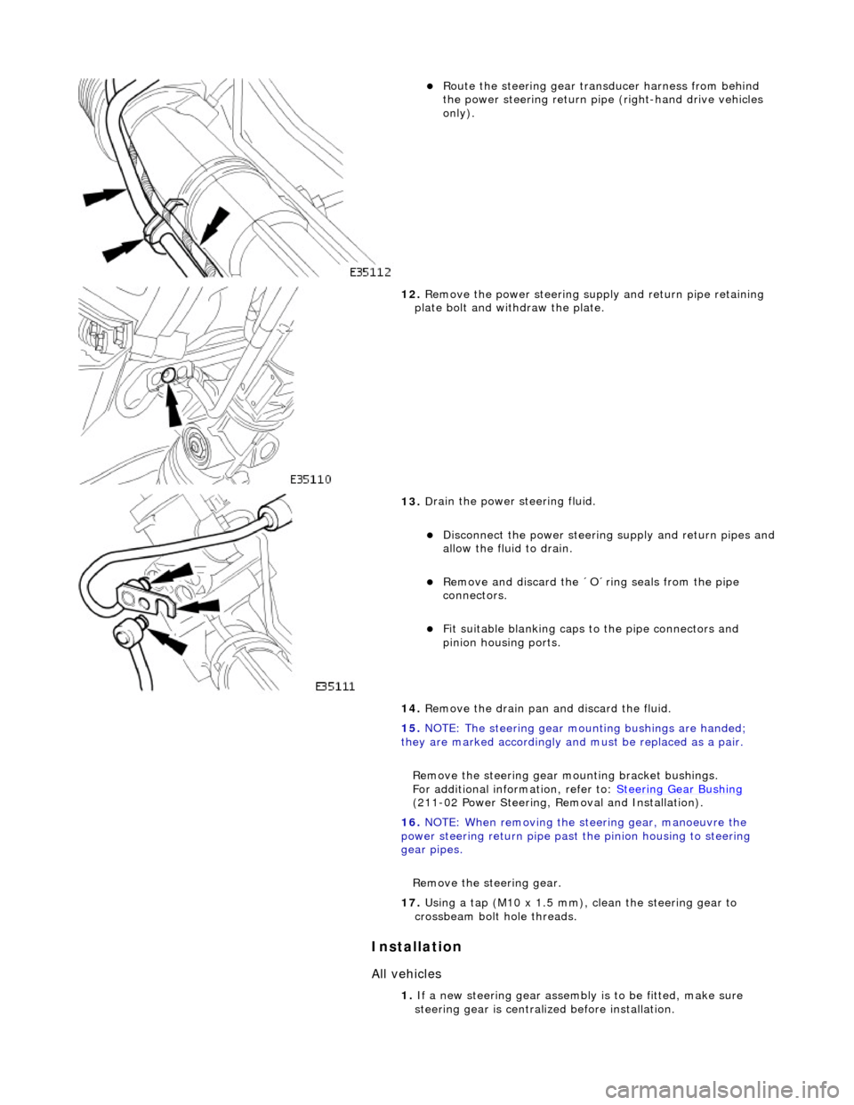
Route t
he steering gear transducer harness from behind
the power steering return pipe (right-hand drive vehicles
only).
12 . Remove the
power steering supply and return pipe retaining
plate bolt and with draw the plate.
13 . D
rain the power steering fluid.
Di
sc
onnect the power steering
supply and return pipes and
allow the fluid to drain.
Remove an d discard the ´O´ring seals from the
pipe
connectors.
Fi t su
itable blanking caps
to the pipe connectors and
pinion housing ports.
14. Remove the drain pan and discard the fluid.
15. NOTE: The steering gear mounting bushings are handed;
they are marked accordingly and must be replaced as a pair.
Remove the steering gear mo unting bracket bushings.
For additional information, refer to: Steering Gear Bushing
( 21
1-02 Power Steering, Removal and Installation).
16. NOTE: When removing the steering gear, manoeuvre the
power steering return pipe past the pinion housing to steering
gear pipes.
Remove the steering gear.
17. Using a tap (M10 x 1.5 mm), clean the steering gear to
crossbeam bolt hole threads.
1. If a new steering gear assembly is to be fitted, make sure
steering gear is centrali zed before installation.
Page 552 of 2490
Engine - Connecting Rod Bearings
In-vehic
le Repair
Remov
a
l
1.
Disc
onnect the batt
ery ground cable.
Re
move the battery cover.
2. Open the engine compartment and fit paintwork protection
sheets.
3. Remove the engine compartmen t cover. Refer to operation
76.16.01.
4. Remove the twin fan and motor assembly. Refer to Operation
26.25.12.
5. Remove the timing cover and al l associated components, as
detailed in Operation 12.65.01.
6. Remove both front wheel and tyre assemblies. Refer to
Operation 74.20.05.
7. Remove the undertray. Re fer to Operation 76.22.90.
8. Remove the front crossmember fo r access. Refer to Operation
76.10.05.
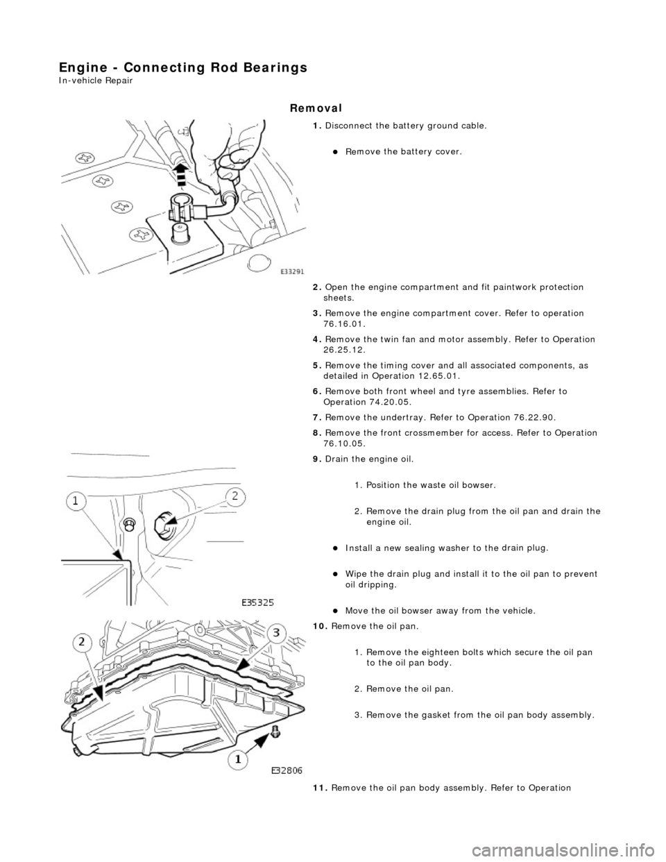
9. Drai
n the engine oil.
1. Position the waste oil bowser.
2. Remove the drain plug from the oil pan and drain the engine oil.
Install a new sealing wash er to the
drain plug.
Wipe the drain plug an
d
install
it to the oil pan to prevent
oil dripping.
Move the oil bowser away f
rom the vehicle.
10 . Re
move the oil pan.
1. Remove the eighteen bolt s which secure the oil pan
to the oil pan body.
2. Remove the oil pan.
3. Remove the gasket from the oil pan body assembly.
11. Remove the oil pan body a ssembly. Refer to Operation
Page 555 of 2490

I
nstallation
Tigh
ten each bolt to 8 to 12 Nm initial torque value.
Ti
ghten to a final torque of 57 to 63 Nm.
27. Check that the cranks haft turns freely.
28. Repeat the previous operations for each connecting rod
bearing as necessary.
1. Install the oil pan bo dy assembly. Refer to Operation 12.60.48.
2. Po
sition and align the oil pan gasket to the oil pan body
assembly.
Inse
rt the seal into the locating positions in the groove,
working around from a corner.
Press in the remai
nder of th
e seal, following the same
procedure.
3. Install th
e oil pan to the oil pan body.
1. Position and align the oil pan.
2. Install, but do not tighte n, all eighteen bolts which
secure the oil pan.
4. Tigh
ten the bolts to the correct
torque figure 11-13 Nm, in the
sequence indicated.
Tigh
ten the drain plug to 30-40 Nm.
Install a new oil
filter.
Page 616 of 2490
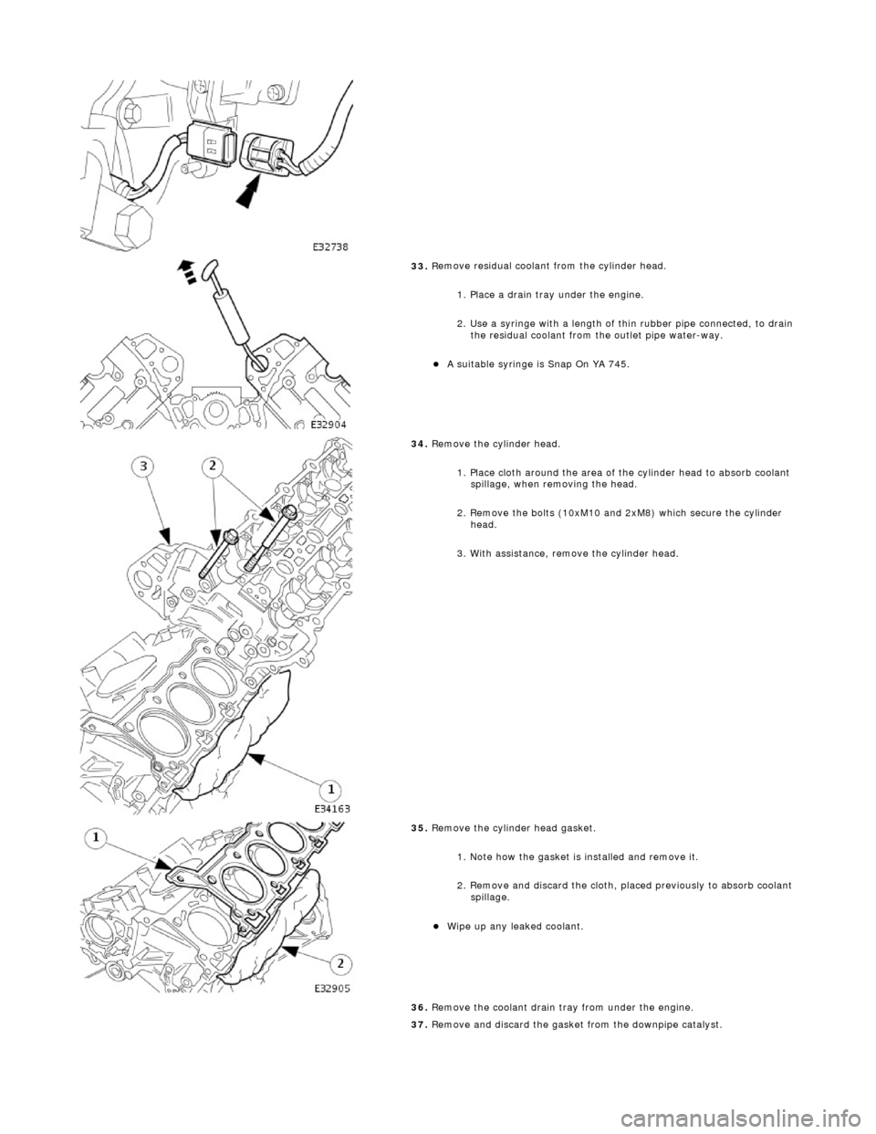
33. R
emove residual coolant from the cylinder head.
1. Place a drain tray under the engine.
2. Use a syringe with a length of thin rubber pipe connected, to drain the residual coolant from the outlet pipe water-way.
A s u
itable syringe is Snap On YA 745.
34 . R
emove the cylinder head.
1. Place cloth around the area of th e cylinder head to absorb coolant
spillage, when removing the head.
2. Remove the bolts (10xM10 and 2xM8) which secure the cylinder head.
3. With assistance, remove the cylinder head.
35 . R
emove the cylinder head gasket.
1. Note how the gasket is installed and remove it.
2. Remove and discard the cloth, placed previously to absorb coolant spillage.
Wipe up any l e
aked coolant.
36. Remove the coolant drain tray from under the engine.
37. Remove and discard the gasket from the downpipe catalyst.
Page 631 of 2490
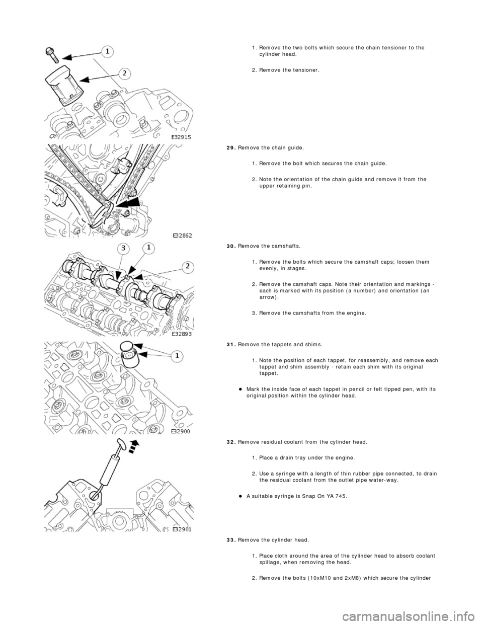
1.
Remove the two bolts which secure the chain tensioner to the
cylinder head.
2. Remove the tensioner.
29
.
Remove the chain guide.
1. Remove the bolt which secures the chain guide.
2. Note the orientation of the chain guide and remove it from the upper retaining pin.
30
.
Remove the camshafts.
1. Remove the bolts which secure the camshaft caps; loosen them evenly, in stages.
2. Remove the camshaft caps. Note their orientation and markings -
each is marked with its position (a number) and orientation (an
arrow).
3. Remove the camshafts from the engine.
31
.
Remove the tappets and shims.
1. Note the position of each tappet, for reassembly, and remove each
tappet and shim assembly - retain each shim with its original
tappet.
Mark
the inside face of each tappet in pencil or felt tipped pen, with its
original position within the cylinder head.
32
.
Remove residual coolant from the cylinder head.
1. Place a drain tray under the engine.
2. Use a syringe with a length of thin rubber pipe connected, to drain the residual coolant from the outlet pipe water-way.
A s
uitable syringe is Snap On YA 745.
33. Remove the cylinder head.
1. Place cloth around the area of th e cylinder head to absorb coolant
spillage, when removing the head.
2. Remove the bolts (10xM10 and 2xM8) which secure the cylinder
Page 632 of 2490

Installation
hea
d.
3. With assistance, remove the cylinder head.
34 . R
emove the cylinder head gasket.
1. Note how the gasket is installed and remove it.
2. Remove and discard the cloth, placed previously to absorb coolant spillage.
Wipe up any l e
aked coolant.
35. Remove the coolant drain tray from under the engine.
36. Remove and discard the gasket from the downpipe catalyst.
Cle
an the gasket faces of the catalyst and the exhaust manifold.
37. Clean cylinder head and cylinder block gasket faces.
Ensu
re that all threaded holes in the cylinder block face are clean and
free from oil.
Cl ean and
inspect the cylinder head bolts. They may be re-used on two
occasions. When re- used, each bolt head should be marked with one
dot from an automatic centre punch.
38. Clean and inspect all relevant components and mating faces.
1. CAUTIONS: If a replacement cylinder head is to be installed to a vehicle with VCT
the cylinder head must have the oil gallery blind rivet removed before
installation.
Make sure that all debris is removed from the cylinder head and cylinder
head oil gallery.
Vehicles fitted with VCT: Remove the blind rivet from the VCT oil gallary. • NOTE: The centre bore of the blind rivet is 6 mm diameter.
Page 696 of 2490
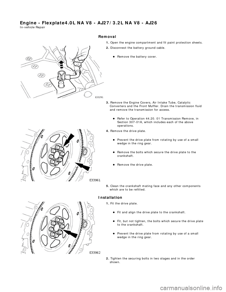
Engine - Flexplate4.0L NA V8 - AJ27/3.2L NA V8 - AJ26
In-vehicle Repair
Removal
Installation
1. Open the engine compartment and fit paint protection sheets.
2. Disconnect the batt ery ground cable.
Remove the battery cover.
3. Remove the Engine Covers, Air Intake Tube, Catalytic
Converters and the Front Muffler. Drain the transmission fluid
and remove the transmission for access.
Refer to Operation 44.20. 01 Transmission Remove, in
Section 307-01A, which includes each of the above
operations.
4. Remove the drive plate.
Prevent the drive plate from rotating by use of a small
wedge in the ring gear.
Remove the bolts which secure the drive plate to the
crankshaft.
Remove the drive plate.
5. Clean the crankshaft mating face and any other components
which are to be refitted.
1. Fit the drive plate.
Fit and align the drive plate to the crankshaft.
Fit, but not tighten, the bolt s which secure the drive plate
to the crankshaft.
Prevent the drive plate from rotating by use of a small
wedge in the ring gear.
2. Tighten the securing bolts in two stages and in the order
shown.
Page 698 of 2490
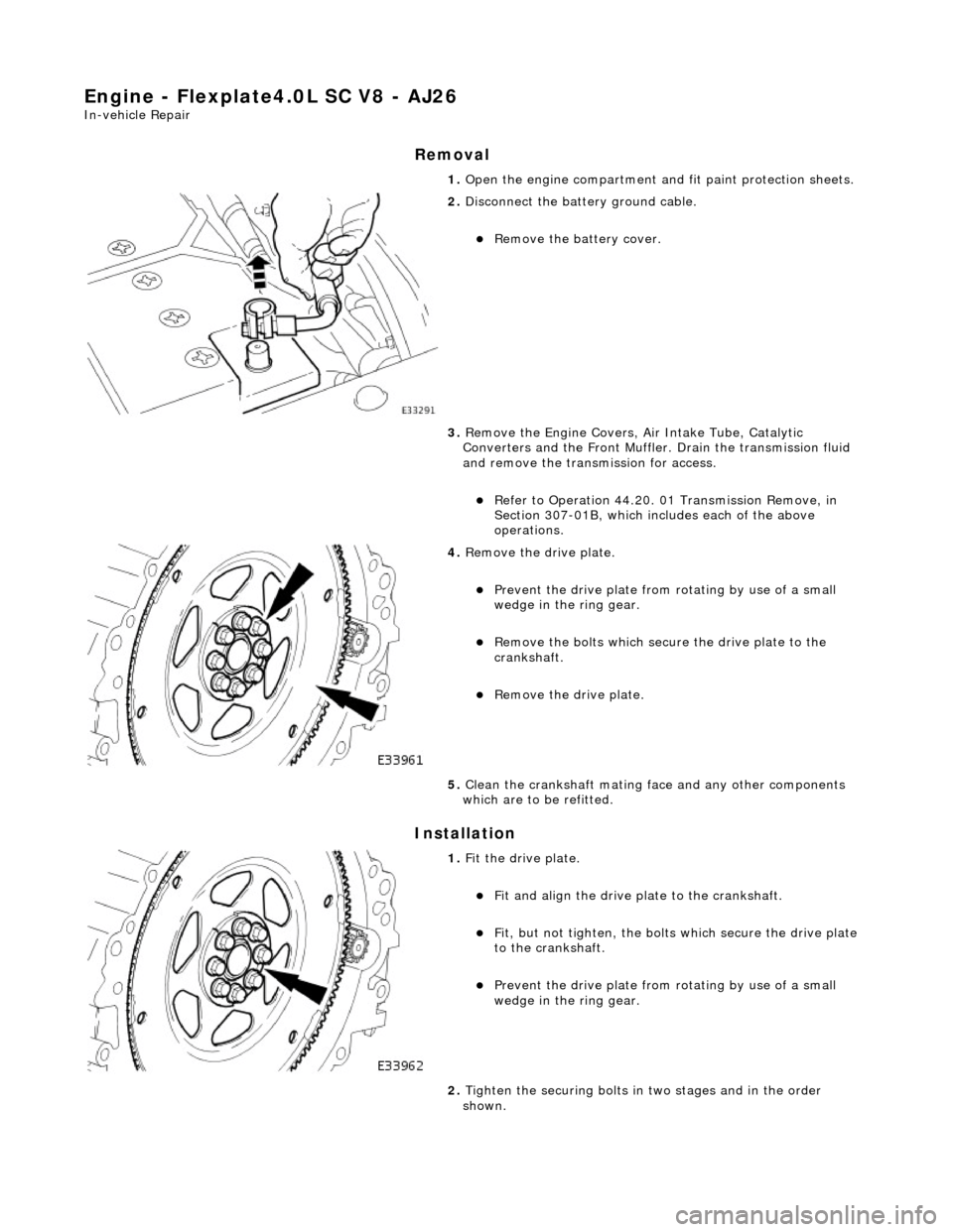
Engine - Flexplate4.0L SC V8 - AJ26
In-vehicle Repair
Removal
Installation
1. Open the engine compartment and fit paint protection sheets.
2. Disconnect the batt ery ground cable.
Remove the battery cover.
3. Remove the Engine Covers, Air Intake Tube, Catalytic
Converters and the Front Muffler. Drain the transmission fluid
and remove the transmission for access.
Refer to Operation 44.20. 01 Transmission Remove, in
Section 307-01B, which includes each of the above
operations.
4. Remove the drive plate.
Prevent the drive plate from rotating by use of a small
wedge in the ring gear.
Remove the bolts which secure the drive plate to the
crankshaft.
Remove the drive plate.
5. Clean the crankshaft mating face and any other components
which are to be refitted.
1. Fit the drive plate.
Fit and align the drive plate to the crankshaft.
Fit, but not tighten, the bolt s which secure the drive plate
to the crankshaft.
Prevent the drive plate from rotating by use of a small
wedge in the ring gear.
2. Tighten the securing bolts in two stages and in the order
shown.