Heel board JAGUAR X308 1998 2.G User Guide
[x] Cancel search | Manufacturer: JAGUAR, Model Year: 1998, Model line: X308, Model: JAGUAR X308 1998 2.GPages: 2490, PDF Size: 69.81 MB
Page 467 of 2490

High
-pitched sound like rubbing a clean window.
Squea
l
Continu
ous, high-pitched sound like runn
ing finger nails across a chalkboard.
Tap
Ligh
t, hammering sound like tapping pencil on edge
of table. May be rhythmic or intermittent.
Weep
Continu
ous mid-range sound (lower frequency
than squeal, higher frequency than groan).
Whir/
Whine
High
-pitched buzzing sound, like
an electric motor or drill.
Whistle
Sharp, shril
l sound, like wi
nd passing a small opening.
Description of Specific St eer
ing System Noise Types
Bel
t Squeal
Belt squea
l is a high frequency air-born
e noise generated by slippage of the ribbe d Vee belt on the power steering pump
pulley. Squeal increases with system loading and at the end of lock.
Clonk
Cl
onk is a structure-borne nois
e heard as a loose-sounding rattle or vibration coming from the steering column. Clonk can
be identified by driving and turning over cobblestones, rough roads, or high frequency bumps such as 25-50 mm tall tar
strips. Clonk requires a tie-rod load impact.
Column Knoc
k
Col
umn knock is a loose-sounding rattle or
vibration generated by the steering column shaft contacting other portions of the
column assembly. The noise is both audible and tactile. Column knock is generate d by driving over cobblestones or rough
pavement. It is not necessary to turn the steering wheel to create this noise.
Column Ra
ttle
Co
lumn rattle is a metallic sounding no
ise created when applying a highly impuls ive force to the steering wheel. Column
rattle is often used to combine the more general group of column noises includin g clonk and column knock. Column rattle
noises can be caused by clonk, knock, l oose column components, bonus parts etc. A series of parked, straight-line driving,
and cornering test should be carried out to isolate the source/sources.
Gr
inding/Scrape
Gr
inding is a low frequency noise in the column when the st
eering wheel is turned. Is generally caused by interference
between moving components such as the st eering wheel to steering column shroud.
Gr
unt (Squawk)
Grunt
is a "honking" sound elicited when coming off one of
the steering stops. Grunt is generally excited during parking
manoeuvres with a low to me dium speed steering input.
Squea
k
Page 491 of 2490
DO NOT DRIVE THE VEHICLE WITH THE TEST EQUIPMENT INSTALLED.
With the control valve CLOSED the pump maximum output pressure can be checked.
Remov
ing Test Equipment
T
o remove the test equipment:
Install a hose clamp
on the
reservoir to pump hose.
Re
moving the test equipmen
t is a reversal of the installation instructions.
Install a new O-r
ing to the PAS pump high
pressure outlet to hose connection.
Inst
all the original hose to the PAS pump.
R
emove the clamp from the reservoir to pump hose.
Top-up the reservoi
r fluid.
B
leed the PAS system; refe
r to this section.
Refer to PDU
User Guide
T
he PDU will diagnose all electrical components of the system.
Before changing a component, chec k fuse No. 12 (10A) in the left-hand heelboard fu se box. However, if this fuse is faulty a
number of other components wi ll also fail to function.
Page 1218 of 2490
Yes
GO to N3.
No
CLEAN th
e sensor and whee
l. INSTALL the sensor.
REFER to Camshaft Position (CMP) Sensor
in this
section.
CLEAR the DTCs. TEST the system for normal operation.
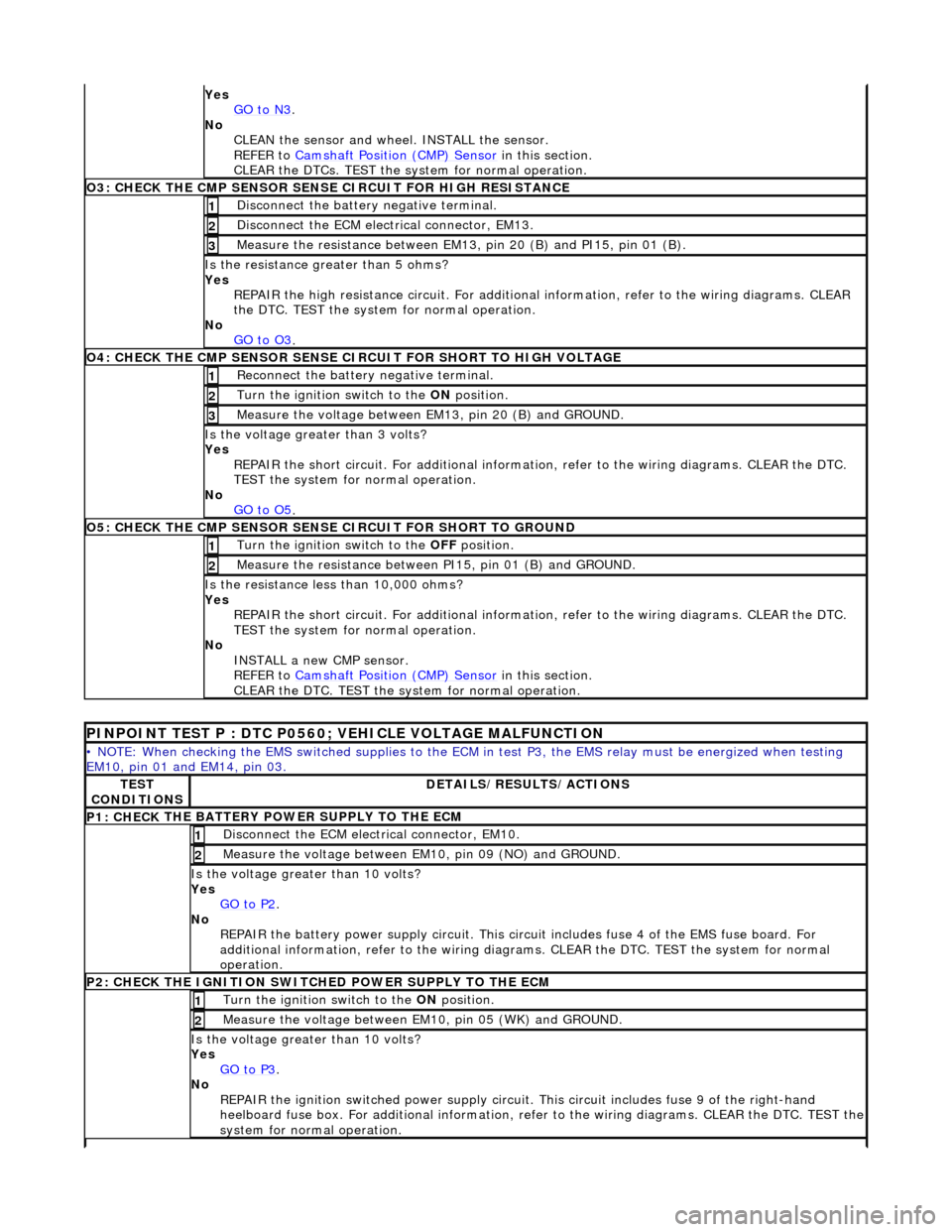
O3: CHECK THE CM P SEN
SOR SENS
E CIRCUIT FOR HIGH RESISTANCE
Disc
onnect the battery negative terminal.
1
D
i
sconnect the ECM electrical connector, EM13.
2
Meas
ure t
he resistance between EM13, pin 20 (B) and PI15, pin 01 (B).
3
Is the res
istance greater than 5 ohms?
Yes REPAIR the high resistance circui t. For additional information, refer to the wiring diagrams. CLEAR
the DTC. TEST the system for normal operation.
No GO to O3
.
O4: CHECK THE CM P SEN
SOR SENSE CI
RCUIT FOR SHORT TO HIGH VOLTAGE
Re
connect the battery negative terminal.
1
Turn the ignition swi
t
ch to the ON
position.
2
Me
asure the voltage between EM13, pin 20 (B) and GROUND.
3
Is th
e volt
age greater than 3 volts?
Yes REPAIR the short circuit. For addi tional information, refer to the wiring diagrams. CLEAR the DTC.
TEST the system for normal operation.
No GO to O5
.
O5: CH ECK THE CM
P SENSOR SENSE CIRCUIT FOR SHORT TO GROUND
Turn the ignition swi
t
ch to the OFF
position.
1
Me
asure the resistance between PI15, pin 01 (B) and GROUND.
2
Is
t
he resistance less than 10,000 ohms?
Yes REPAIR the short circuit. For addi tional information, refer to the wiring diagrams. CLEAR the DTC.
TEST the system for normal operation.
No INSTALL a new CMP sensor.
REFER to Camshaft Position (CMP) Sensor
in this
section.
CLEAR the DTC. TEST the system for normal operation.
P I
NPOINT TEST P : DTC P0560; VEHICLE VOLTAGE MALFUNCTION
•
NOTE
: When checking the EMS switched supplies to the ECM
in test P3, the EMS relay must be energized when testing
EM10, pin 01 and EM14, pin 03.
TE S
T
CONDITIONS
D E
TAILS/RESULTS/ACTIONS
P1: CHECK
THE BATTERY POWER SUPPLY TO THE ECM
D
i
sconnect the ECM electrical connector, EM10.
1
Measure the
voltage between EM 10,
pin 09 (NO) and GROUND.
2
Is the vol
t
age greater than 10 volts?
Yes GO to P2
.
No
REPAIR th
e battery power supply circ
uit. This circuit includes fuse 4 of the EMS fuse board. For
additional information, refer to the wiring diagrams. CLEAR the DT C. TEST the system for normal
operation.
P2: CHECK
THE IGNITION SWITCH
ED POWER SUPPLY TO THE ECM
Turn the ignition swit
ch to the
ON position.
1
Meas
ure t
he voltage between EM10, pin 05 (WK) and GROUND.
2
Is the vol
t
age greater than 10 volts?
Yes GO to P3
.
No
REP
AIR the ignition switched power supply circuit. This circuit includes fuse 9 of the right-hand
heelboard fuse box. For a dditional information, refer to the wiri ng diagrams. CLEAR the DTC. TEST the
system for normal operation.
Page 1219 of 2490
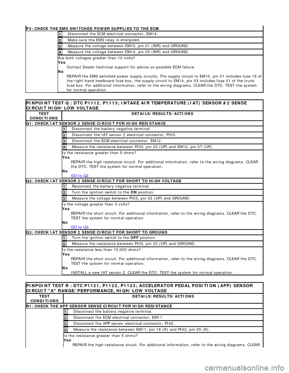
P3: CHECK
THE EMS SWITCHED
POWER SUPPLIES TO THE ECM
D
isconnect the ECM electrical connector, EM14.
1
Make sure the EMS re
lay i
s energized.
2
Meas
ure the voltage between EM10, pin 01 (WR) and GROUND.
3
Meas
ure the voltage between EM14, pin 03 (WR) and GROUND.
4
Are both
voltages greater than 10 volts?
Yes Contact Dealer technical support for advice on possible ECM failure.
No REPAIR the EMS switched power supply circuits. The su pply circuit to EM10, pin 01 includes fuse 18 of
the right-hand heelboard fuse box, the supply circuit to EM14, pin 03 includes fuse 01 of the trunk
fuse box. For additional information, refer to th e wiring diagrams. CLEAR the DTC. TEST the system
for normal operation.
PI
NPOINT TEST Q : DTC P1112, P1113; INTAKE
AIR TEMPERATURE (IAT) SENSOR #2 SENSE
CIRCUIT HIGH/LOW VOLTAGE
TE
ST
CONDITIONS
D
ETAILS/RESULTS/ACTIONS
Q1:
CHECK IAT SENSOR 2 SENSE CIRCUIT FOR HIGH RESISTANCE
Di
sconnect the battery negative terminal.
1
Di
sconnect the IAT sensor 2 electrical connector, PI03.
2
D
isconnect the ECM electrical connector, EM12.
3
Me
asure the resistance between PI03, pin 02 (UP) and EM12, pin 07 (UP).
4
Is th
e resistance greater than 5 ohms?
Yes REPAIR the high resistance circui t. For additional information, refer to the wiring diagrams. CLEAR
the DTC. TEST the system for normal operation.
No GO to Q2
.
Q2: CH
ECK IAT SENSOR 2 SENSE CIRC
UIT FOR SHORT TO HIGH VOLTAGE
R
econnect the battery negative terminal.
1
Turn the ignition swi
tch to the ON
position.
2
Measure the
voltage between PI
03, pin 02 (UP) and GROUND.
3
Is th
e voltage greater than 3 volts?
Yes REPAIR the short circuit. For addi tional information, refer to the wiring diagrams. CLEAR the DTC.
TEST the system for normal operation.
No GO to Q3
.
Q3:
CHECK IAT SENSOR 2 SENSE CIRCUIT FOR SHORT TO GROUND
Turn the ignition swi
tch to the OFF
position.
1
Meas
ure the resistance between PI03, pin 02 (UP) and GROUND.
2
Is
the resistance less than 10,000 ohms?
Yes REPAIR the short circuit. For addi tional information, refer to the wiring diagrams. CLEAR the DTC.
TEST the system for normal operation.
No INSTALL a new IAT sensor 2. CLEAR the DTC. TEST the system for normal operation.
P
INPOINT TEST R : DTC P1121, P1122, P1123;
ACCELERATOR PEDAL POSITION (APP) SENSOR
CIRCUIT "A" RANGE/PERFORMANCE, HIGH/LOW VOLTAGE
TE
ST
CONDITIONS
D
ETAILS/RESULTS/ACTIONS
R1: CHECK THE APP
SENSOR SENSE CIRCUIT FOR HIGH RESISTANCE
Di
sconnect the battery negative terminal.
1
D
isconnect the ECM electrical connector, EM11.
2
Di
sconnect the APP sensor electrical connector, PI42.
3
Meas
ure the resistance between EM11, pin 16 (K) and PI42, pin 05 (K).
4
Is th
e resistance greater than 5 ohms?
Yes REPAIR the high resistance circui t. For additional information, refer to the wiring diagrams. CLEAR
Page 1861 of 2490
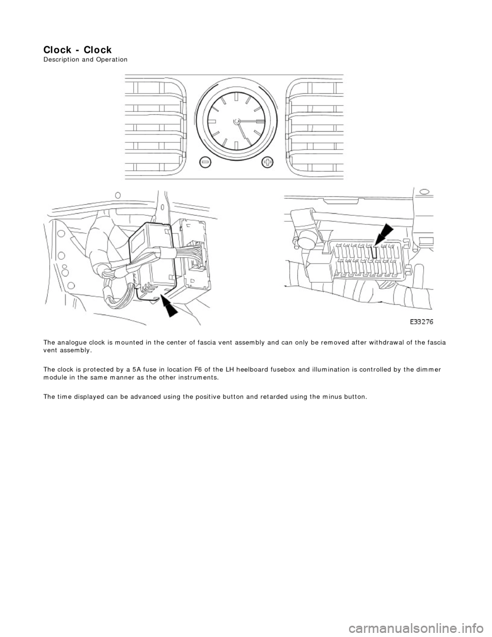
Clock - Clock
Description and Operation
The analogue clock is mounted in the center of fascia vent assembly and can only be removed after withdrawal of the fascia
vent assembly.
The clock is protected by a 5A fuse in lo cation F6 of the LH heelboard fusebox and illumination is controlled by the dimmer
module in the same manner as the other instruments.
The time displayed can be advanced using the positive button and retarded using the minus button.
Page 1963 of 2490
Rear courtesy/ reading lamps
Each rear quarter of the passenger compartment is fitted with combined lighting units comprising; a rear courtesy lamp and
reading lamp. The courtesy lamps operate automatically whenever a rear door is opened; the reading lamps function when
the integral switches are operated by occupants of the vehicle.
Trunk lamps
The trunk trim panel is fitted with lamps which operate auto matically whenever the trunk lid is opened; the switch is
incorporated within the latch mechanism.
Vanity mirror lamps
The vanity mirror lamps, two on each sun visor, operate auto matically when the mirror flap is opened, provided the sun
visor spindle is engage d in the stowage clip.
Operation
The BPM provides an enable signal for the glovebox, vanity mirror, trunk lid and map lamps. Actuation of the relevant
switch provides an earth path to the lamp.
The rear passenger reading lamps receive a supply di rect from fuse F10 in the RH heelboard fuse-box.
The front and rear courtesy lamps have separa te fade functions controlled by the BPM.
The door hazard / puddle lamps are controll ed locally by the relevant Door Module.
Fault analysis must be undertaken using the PDU, refer to Diagnosis and Testing.
Refer to the relevant Electrical Guid e for details of circuit operation.
Page 1973 of 2490
Module Communications Network - Communications Network
Description and Operation
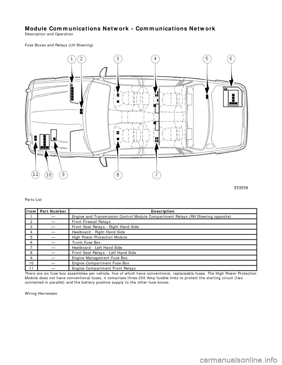
Fuse Boxes and Relays (LH Steering)
Parts List
There are six fuse box assemblies per vehicle, five of which have conventional, replaceable fuses. The High Power Protection
Module does not have conventional fuses, it comprises three 250 Amp fusible links to protect the starting circuit (two
connected in parallel) and the battery positive supply to the other fuse boxes.
Wiring Harnesses
ItemPart NumberDescription
1—Engine and Transmission Cont rol Module Compartment Relays (RH Steering opposite)
2—Front Firewall Relays
3—Front Seat Relays - Right Hand Side
4—Heelboard - Right Hand Side
5—High Power Protection Module
6—Trunk Fuse Box
7—Heelboard - Left Hand Side
8—Front Seat Relays - Left Hand Side
9—Engine Management Fuse Box
10—Engine Compartment Fuse Box
11—Engine Compartment Front Relays
Page 1976 of 2490
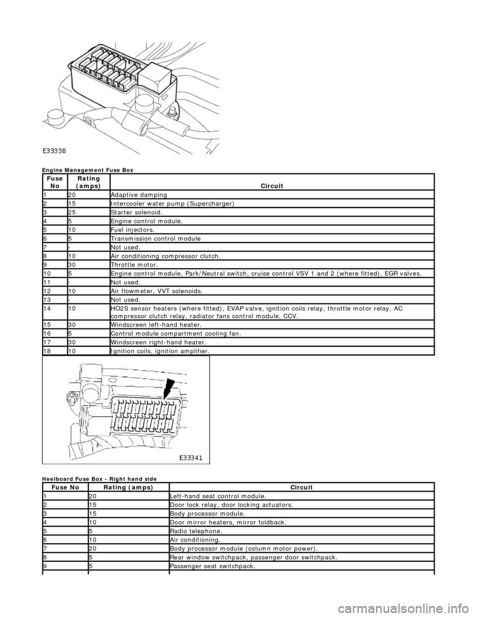
Engine Management Fuse Box
Heelboard Fuse Box - Right hand side
Fuse NoRating
(amps)Circuit
120Adaptive damping
215Intercooler water pump (Supercharger)
325Starter solenoid.
45Engine control module.
510Fuel injectors.
65Transmission control module
7-Not used.
810Air conditioning compressor clutch.
930Throttle motor.
105Engine control module, Park/Neutr al switch, cruise control VSV 1 and 2 (where fitted), EGR valves.
11-Not used.
1210Air flowmeter, VVT solenoids.
13-Not used.
1410HO2S sensor heaters (where fitted ), EVAP valve, ignition coils relay, throttle motor relay, AC
compressor clutch relay, radi ator fans control module, CCV.
1530Windscreen left-hand heater.
165Control module compartment cooling fan.
1730Windscreen right-hand heater.
1810Ignition coils, ignition amplifier.
Fuse NoRating (amps)Circuit
120Left-hand seat control module.
215Door lock relay, door locking actuators.
315Body processor module.
410Door mirror heaters, mirror foldback.
55Radio telephone.
610Air conditioning.
720Body processor module (column motor power).
85Rear window switchpack, passenger door switchpack.
95Passenger seat switchpack.
Page 1977 of 2490
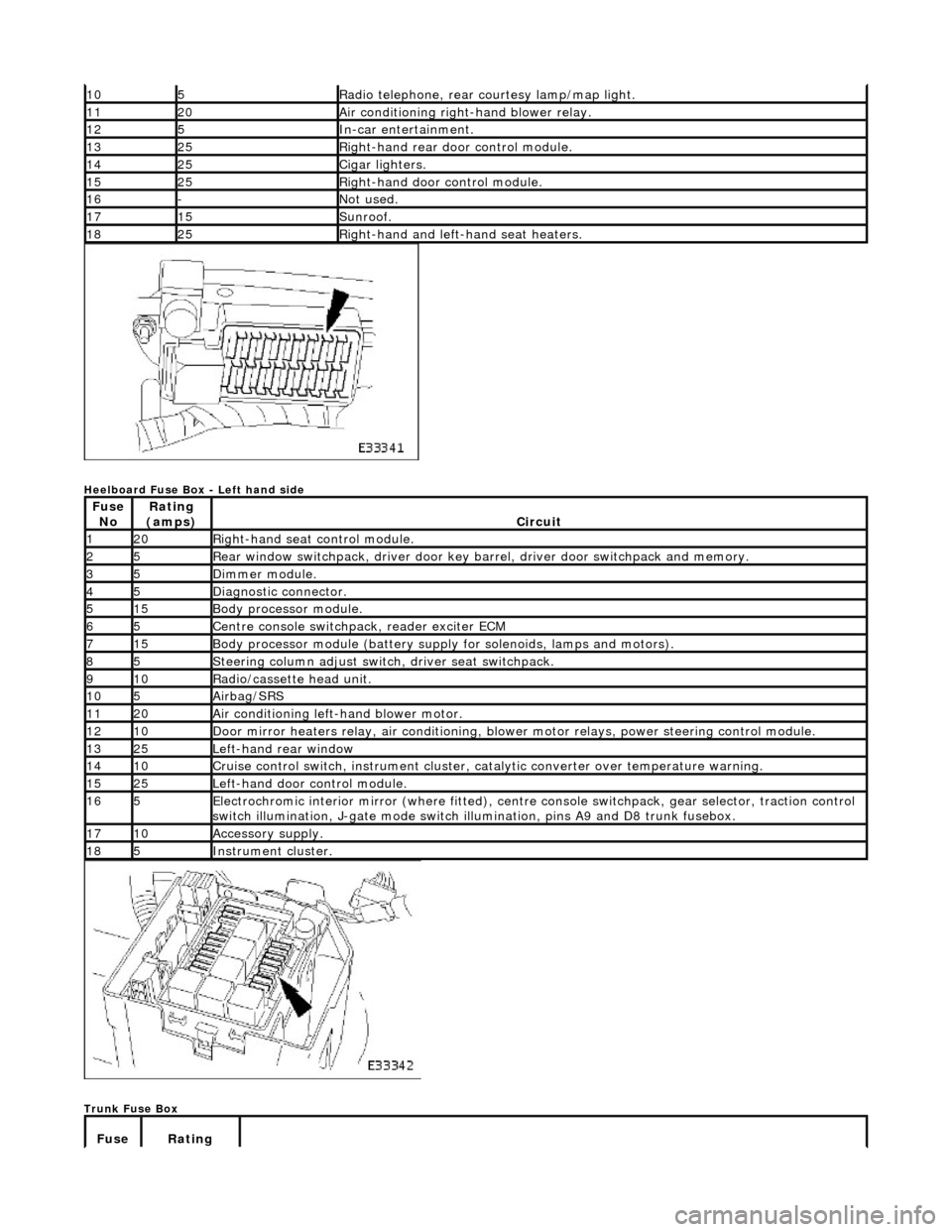
Heelboard Fuse Box - Left hand side
Trunk Fuse Box
105Radio telephone, rear courtesy lamp/map light.
1120Air conditioning right-hand blower relay.
125In-car entertainment.
1325Right-hand rear door control module.
1425Cigar lighters.
1525Right-hand door control module.
16-Not used.
1715Sunroof.
1825Right-hand and left-hand seat heaters.
Fuse NoRating
(amps)Circuit
120Right-hand seat control module.
25Rear window switchpack, driver door key ba rrel, driver door switchpack and memory.
35Dimmer module.
45Diagnostic connector.
515Body processor module.
65Centre console switchpack, reader exciter ECM
715Body processor module (battery supply for solenoids, lamps and motors).
85Steering column adjust switch, driver seat switchpack.
910Radio/cassette head unit.
105Airbag/SRS
1120Air conditioning left-hand blower motor.
1210Door mirror heaters relay, air conditioning, blow er motor relays, power steering control module.
1325Left-hand rear window
1410Cruise control switch, instrument cluster, catalytic converter over temperature warning.
1525Left-hand door control module.
165Electrochromic interior mirror (where fitted), centre console switchpack, gear selector, traction control
switch illumination, J-gate mode switch illumination, pins A9 and D8 trunk fusebox.
1710Accessory supply.
185Instrument cluster.
Fuse Rating
Page 1978 of 2490
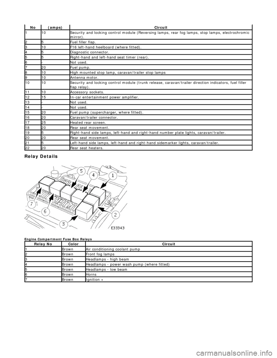
Relay Details
Engine Compartment Fuse Box Relays
No(amps)Circuit
110Security and locking control module (Reversing lamps, rear fog lamps, stop lamps, electrochromic
mirror).
25Fuel filler flap.
310F16 left-hand heelboard (where fitted).
45Diagnostic connector.
55Right-hand and left-han d seat timer (rear).
6-Not used.
720Fuel pump.
810High mounted stop lamp, caravan/trailer stop lamps
910Antenna motor.
1010Security and locking control module (trunk release, caravan/trailer direction indicators, fuel filler
flap relay).
1110Accessory sockets.
1215In-car entertainment power amplifier.
13-Not used.
14-Not used.
1520Fuel pump (supercharger, where fitted).
1620Caravan/trailer connector.
1725Heated rear screen.
1820Rear seat movement.
195Right-hand side lamps, left-h and and right-hand number pl ate lights, caravan/trailer.
2020Rear seat movement.
215Left-hand side lamps, left-hand and right-hand sidemarker lights, caravan/trailer.
2220Rear seat heaters.
Relay NoColorCircuit
1BrownAir conditioning coolant pump
2BrownFront fog lamps
3BrownHeadlamps - high beam
4BrownHeadlamps - power wash pump (where fitted)
5BrownHeadlamps - low beam
6BrownHorns
7BrownIgnition +