Heel board JAGUAR X308 1998 2.G Workshop Manual
[x] Cancel search | Manufacturer: JAGUAR, Model Year: 1998, Model line: X308, Model: JAGUAR X308 1998 2.GPages: 2490, PDF Size: 69.81 MB
Page 137 of 2490
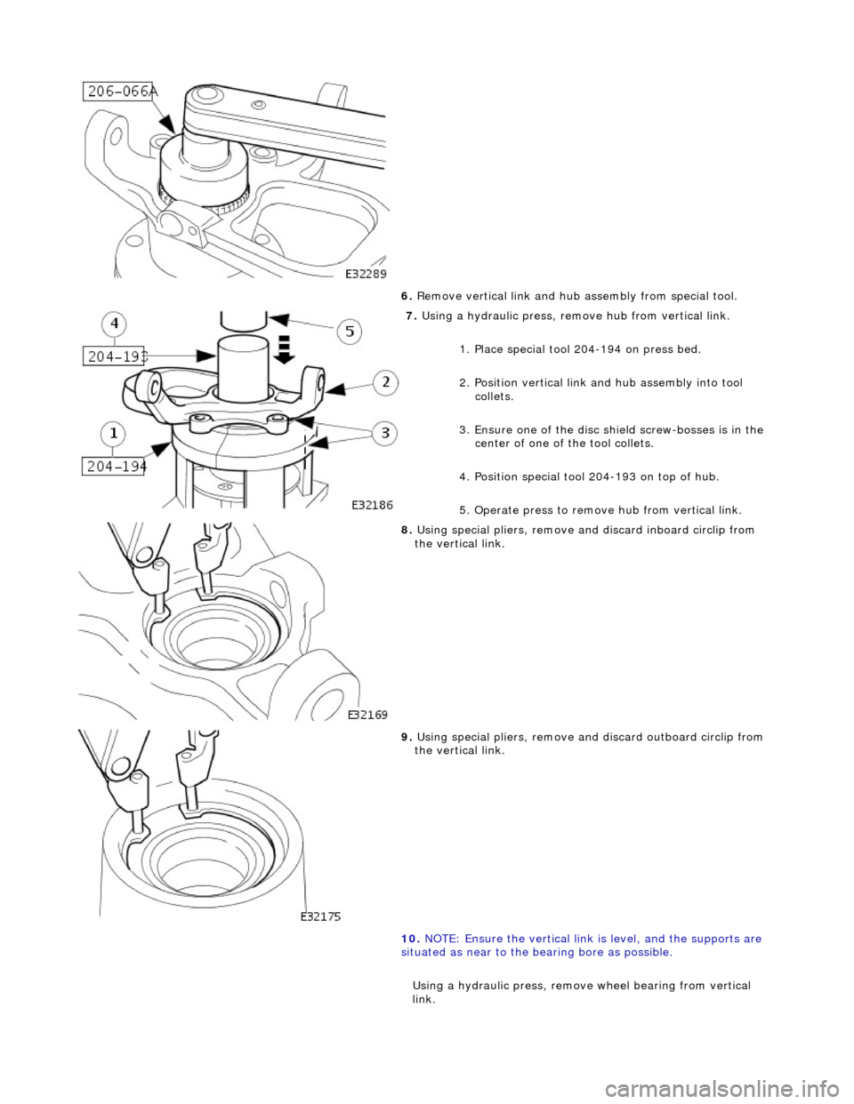
6. R
emove vertical link and hub assembly from special tool.
7. Using a h
ydraulic press, remo
ve hub from vertical link.
1. Place special tool 204-194 on press bed.
2. Position vertical link and hub assembly into tool collets.
3. Ensure one of the disc sh ield screw-bosses is in the
center of one of the tool collets.
4. Position special tool 204-193 on top of hub.
5. Operate press to remove hub from vertical link.
8. U
sing special pliers, remove an
d discard inboard circlip from
the vertical link.
9. U
sing special pliers, remove an
d discard outboard circlip from
the vertical link.
10. NOTE: Ensure the vertical link is level, and the supports are
situated as near to the bearing bore as possible.
Using a hydraulic press, remove wheel bearing from vertical
link.
Page 138 of 2490

In
stallation
1.
Position the vertical link so that inboard side of the
bearing bore is resting on suitable supports on the
press-bed.
2. Position special tool 204-197 on top of bearing.
3. Operate press to remove bearing from vertical link,
discard bearing.
11. Clean relevant parts.
1. NOTE : Th
e gap between the ears of the circlip must be
positioned so that it is in the lowest position of the bore when the
vertical link is installed on the vehicle. Refer to General
Procedures for further information.
Install outboard circlip in vertical link.
2. Using a h y
draulic press, install
bearing in the vertical link.
1. Position vertical link on the press bed with outboard
side of the vertical link face down.
2. Position bearing on vertical link.
3. Position special tool on top of wheel bearing.
4. Operate press to install be aring, applying a three-ton
load to ensure that the bearing is fully seated.
3. CAUTIO
N: To prevent damage to the integral wheel-
bearing seal, select circlip plier en ds that do not protrude through
the circlip ears.
4. NOTE : Th
e gap between the ears of the circlip must be
positioned so that it is in the lowest position of the bore, when the
vertical link is installed on the vehicle. Refer to General
Procedures for further information.
Page 139 of 2490

Inst
all inboard circli
p in vertical link.
5. U
sing a hydraulic press, install hub in vertical link.
1. Position special tool on press bed.
2. Position the vertical link on the tool, with the inboard-side face down.
3. Position hub on bearing.
4. Position a flat steel plate across the face of the hub,
DO NOT place plate ac ross wheel studs.
5. Operate press to install the hub, applying a three-ton
load to ensure hub is fully seated in bearing.
6. U
sing special tool, secure vertical link and hub assembly in a
vise.
Secure special
tool in a vise.
Posit
ion hub in tool.
Inst
all wheel nuts.
7. Install
rotor nut .
1. Install rotor nut on hub.
2. Using special tool tighten rotor nut.
8. CAUTION: Do not slacken the rotor nut to engage the
spring clip.
• NOTE: If the castellated slots of the rotor nut are not aligned,
tighten the rotor nut further unti l the spring clip engages the
Page 143 of 2490
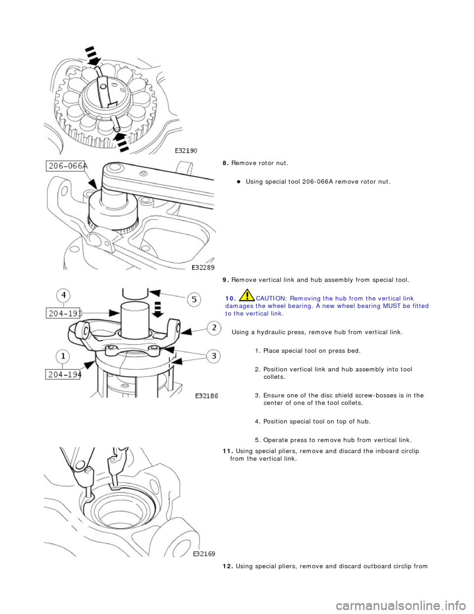
8. R
emove rotor nut.
U
sing special tool 206-066A remove rotor nut.
9. Remove vertical link and hub assembly from special tool.
10
.
CAUTION: Removing the hu b from the vertical link
damages the wheel bearing. A new wheel bearing MUST be fitted
to the vertical link.
Using a hydraulic press, remo ve hub from vertical link.
1. Place special tool on press bed.
2. Position vertical link and hub assembly into tool collets.
3. Ensure one of the disc sh ield screw-bosses is in the
center of one of the tool collets.
4. Position special tool on top of hub.
5. Operate press to remove hub from vertical link.
11
.
Using special pliers, remove an d discard the inboard circlip
from the vertical link.
12. Using special pliers, remove an d discard outboard circlip from
Page 144 of 2490

In
stallation
the vertical li
nk.
13 . N
OTE: Ensure
the vertical link is level, and the supports are
situated as near to the bearing bore as possible.
Using a hydraulic press, remove wheel bearing from the vertical
link.
1. Position the vertical link so that the inboard side of the bearing bore is resting on suit able supports on
the press-bed.
2. Position special tool 204-197 on top of bearing.
3. Operate press to remove bearing from vertical link,
discard bearing.
14. Clean relevant parts.
1. NOTE : Th
e gap between the ears of the circlip must be
positioned so that it is in the lowest position of the bore when the
vertical link is installed on the vehicle. Refer to General
Procedures for further information.
Install outboard circlip in vertical link.
2. Usi ng a h
ydraulic press, install wheel bearing in vertical link.
1. Position vertical link on the press bed with outboard
side of the vertical link face down.
2. Position wheel bearing on vertical link.
3. Position special tool on top of wheel bearing.
4. Operate press to install be aring, applying a three-ton
seating load to ensure the bearing is fully seated.
3. CAUTION: To prevent damage to the integral bearing
seal, select circlip plier ends th at do not protrude through the
circlip ears.
Page 145 of 2490
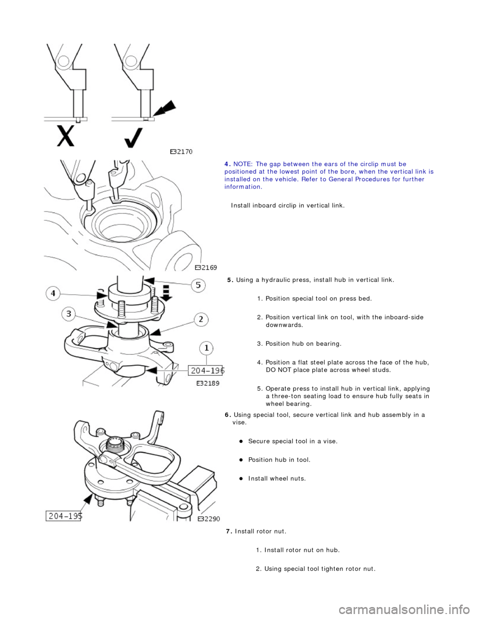
4. NOTE
: The gap between the ears of the circlip must be
positioned at the lowest point of the bore, when the vertical link is
installed on the vehicl e. Refer to General Procedures for further
information.
Install inboard circli p in vertical link.
5. U
sing a hydraulic press, install hub in vertical link.
1. Position special tool on press bed.
2. Position vertical link on tool, with the inboard-side downwards.
3. Position hub on bearing.
4. Position a flat steel plate across the face of the hub,
DO NOT place plate ac ross wheel studs.
5. Operate press to install hu b in vertical link, applying
a three-ton seating load to ensure hub fully seats in
wheel bearing.
6. U
sing special tool, secure vertical link and hub assembly in a
vise.
Secure special
tool in a vise.
Posit
ion hub in tool.
Inst
all wheel nuts.
7. Install rotor nut.
1. Install rotor nut on hub.
2. Using special tool tighten rotor nut.
Page 149 of 2490
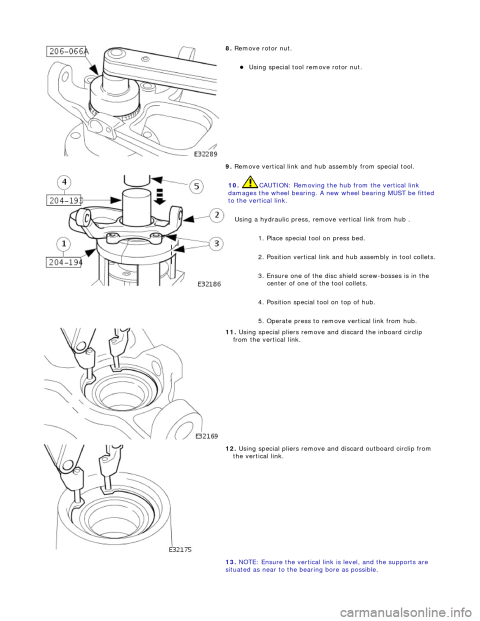
8. R
emove rotor nut.
Using speci
al tool remove rotor nut.
9. Remove vertical link and hub assembly from special tool.
10
.
CAUTION: Removing the hu b from the vertical link
damages the wheel bearing. A new wheel bearing MUST be fitted
to the vertical link.
Using a hydraulic press, remo ve vertical link from hub .
1. Place special tool on press bed.
2. Position vertical link and hub assembly in tool collets.
3. Ensure one of the disc sh ield screw-bosses is in the
center of one of the tool collets.
4. Position special tool on top of hub.
5. Operate press to remove vertical link from hub.
11
.
Using special pliers remove an d discard the inboard circlip
from the vertical link.
12
.
Using special pliers remove an d discard outboard circlip from
the vertical link.
13. NOTE: Ensure the vertical link is level, and the supports are
situated as near to the bearing bore as possible.
Page 150 of 2490

In
stallation
Using a hy
draulic press, remove
wheel bearing from the vertical
link.
1. Position the vertical link so that the inboard side of the bearing bore is resting on suit able supports on
the press-bed.
2. Position special tool on top of bearing.
3. Operate press to remove bearing from vertical link,
discard bearing.
14. Clean relevant parts.
1. NOTE : Th
e gap between the ears of the circlip must be
positioned so that it is in the lowest position of the bore when the
vertical link is installed on the vehicle. Refer to General
Procedures for further information.
Install outboard circlip in vertical link.
2. Using a h y
draulic press, instal
l bearing in vertical link.
1. Position vertical link on the press bed with outboard
side of the vertical link face down.
2. Position wheel bearing on vertical link.
3. Position special tool on top of wheel bearing.
4. Operate press to install the bearing, applying a three- ton seating load to ensure bearing is fully seated.
3. CAUTIO
N: To prevent damage to the integral bearing
seal, select circlip plier ends th at do not protrude through the
circlip ears.
4. NOTE : Th
e gap between the ears of the circlip must be
positioned at the lowest point of the bore, when the vertical link is
installed on the vehicl e. Refer to General Procedures for further
information.
Page 151 of 2490
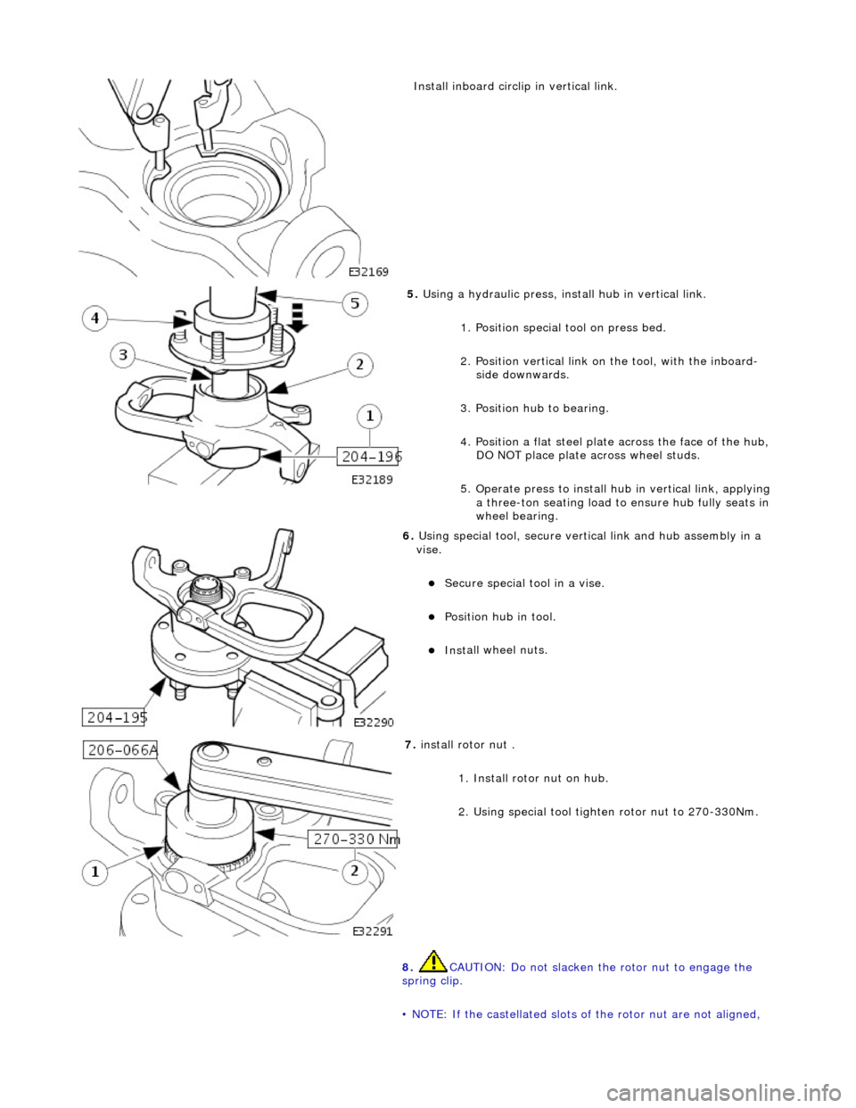
Inst
all inboard circli
p in vertical link.
5. U
sing a hydraulic press, install hub in vertical link.
1. Position special tool on press bed.
2. Position vertical link on the tool, with the inboard-side downwards.
3. Position hub to bearing.
4. Position a flat steel plate across the face of the hub,
DO NOT place plate ac ross wheel studs.
5. Operate press to install hu b in vertical link, applying
a three-ton seating load to ensure hub fully seats in
wheel bearing.
6. U
sing special tool, secure vertical link and hub assembly in a
vise.
Secure special
tool in a vise.
Posit
ion hub in tool.
Inst
all wheel nuts.
7. i
nstall rotor nut .
1. Install rotor nut on hub.
2. Using special tool tighten rotor nut to 270-330Nm.
8. CAUTION: Do not slacken the rotor nut to engage the
spring clip.
• NOTE: If the castellated slots of the rotor nut are not aligned,
Page 317 of 2490
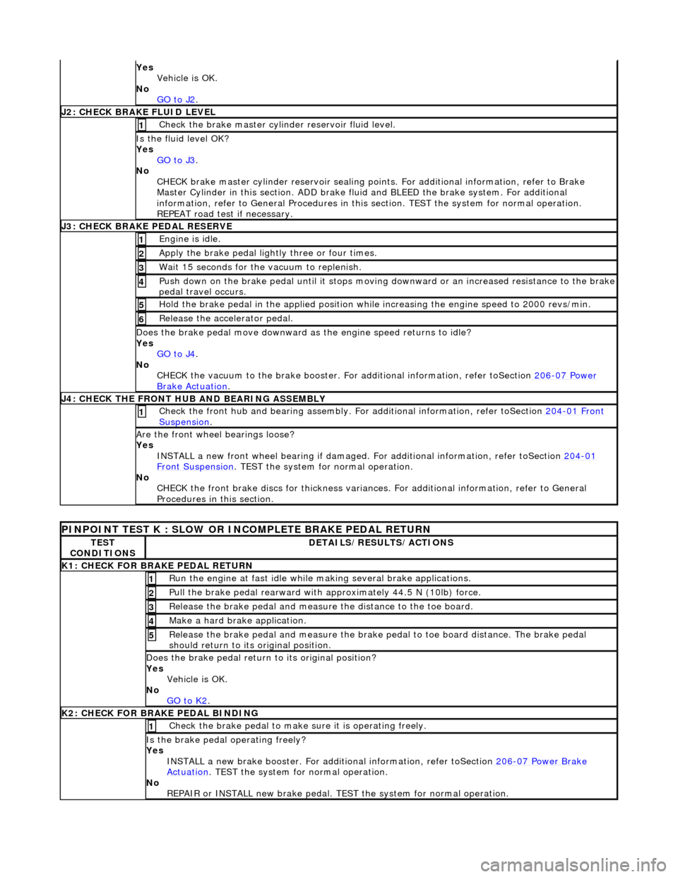
Yes
Vehicle is OK.
No GO to J2
.
J
2: CHECK BRAKE FLUID LEVEL
Check the brake master cyli
nder reservoir fluid level.
1
Is the fl
uid level OK?
Yes GO to J3
.
No
CHECK brake master cylinder reservoir sealing points. For additional information, refer to Brake
Master Cylinder in this section. ADD brake fl uid and BLEED the brake system. For additional
information, refer to General Proc edures in this section. TEST the system for normal operation.
REPEAT road test if necessary.
J
3: CHECK BRAKE PEDAL RESERVE
Engine is
idle.
1
Apply the brake pedal ligh
tl
y three or four times.
2
W
ait 15 seconds for the vacuum to replenish.
3
Push down on
the brake pedal until it stops moving
downward or an increased resistance to the brake
pedal travel occurs.
4
Hol
d the brake pedal in the applied position while increasing the engine speed to 2000 revs/min.
5
Re
lease the accelerator pedal.
6
Does th
e brake pedal move downward as
the engine speed returns to idle?
Yes GO to J4
.
No
CHECK the vacuum to the brake booster. Fo r additional information, refer toSection 206
-0
7 Power
Brake Ac
tuation
.
J
4: CHECK THE FRONT HUB AND BEARING ASSEMBLY
Check the fr
ont hub and bearing assembly. Fo
r additional information, refer toSection 204
-01
Front
Suspe
nsion
. 1
Are th
e front wheel bearings loose?
Yes INSTALL a new front wheel bearin g if damaged. For additional information, refer toSection 204
-01
F
ront Suspension
. TEST
the system for normal operation.
No CHECK the front brake discs for thickness variances. For additional information, refer to General
Procedures in this section.
PINPO
INT TEST K : SLOW OR INCOMPLETE BRAKE PEDAL RETURN
TE
ST
CONDITIONS
D
ETAILS/RESULTS/ACTIONS
K1: C
HECK FOR BRAKE PEDAL RETURN
Ru
n the engine at fast idle while
making several brake applications.
1
Pull the
brake pedal rearward with approximately 44.5 N (10lb) force.
2
Relea
se the brake pedal and measure
the distance to the toe board.
3
Make a hard brake
application.
4
Relea
se the brake pedal and measure the brake
pedal to toe board distance. The brake pedal
should return to its original position.
5
Does th
e brake pedal return
to its original position?
Yes Vehicle is OK.
No GO to K2
.
K
2: CHECK FOR BRAKE PEDAL BINDING
Check the brake pedal to make
s
ure it is operating freely.
1
Is th
e brake pedal operating freely?
Yes INSTALL a new brake booster. For addi tional information, refer toSection 206
-0
7 Power Brake
Actuation. TEST
the system for normal operation.
No REPAIR or INSTALL new brake pedal. TE ST the system for normal operation.