check transmission fluid JAGUAR X308 1998 2.G User Guide
[x] Cancel search | Manufacturer: JAGUAR, Model Year: 1998, Model line: X308, Model: JAGUAR X308 1998 2.GPages: 2490, PDF Size: 69.81 MB
Page 1344 of 2490

Hold the housing assembly in a vice with soft jaws fitted
and carefully insert the coupling.
Fit tool 205 - 053 to the coupling.
3. Use tool 307 - 356 to tighten th e coupling nut to the specified
torque figure.
4. Stake the coupling nut at two positions.
5. Refit the rear extension housing. Refer to Operation 44.20.19.
6. Check the transmission fluid level. Refer to Operation
44.24.02.
Page 1347 of 2490
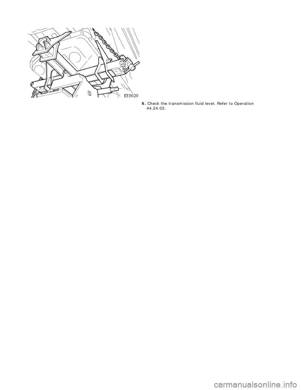
6. Check the transmission fluid level. Refer to Operation
44.24.02.
Page 1351 of 2490
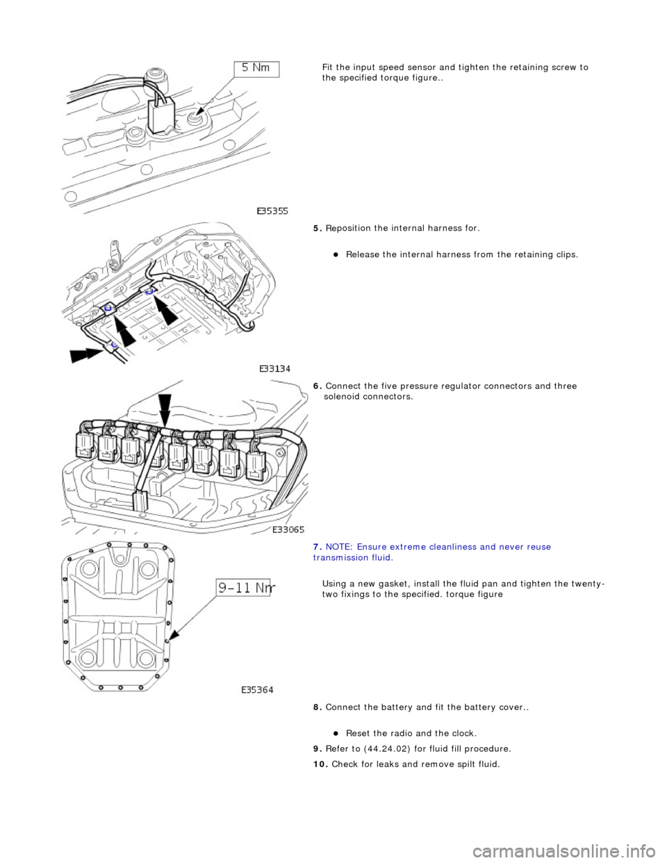
Fit the inpu
t speed sensor and
tighten the retaining screw to
the specified to rque figure..
5. Re
position the inte
rnal harness for.
R
elease the internal harness
from the retaining clips.
6. Connect
the five pressure re
gulator connectors and three
solenoid connectors.
7. N
OTE: Ensure extreme clea
nliness and never reuse
transmission fluid.
Using a new gasket, install the fl uid pan and tighten the twenty-
two fixings to the specified. torque figure
8. Connect the battery and fit the battery cover..
Reset th
e radio and the clock.
9. Refer to (44.24.02) for fluid fill procedure.
10. Check for leaks and remove spilt fluid.
Page 1389 of 2490
Automatic Transmission/Transaxle - 4.0L SC V8 - AJ26 - Transmission
Description
Description and Operation
Transmission Assembly
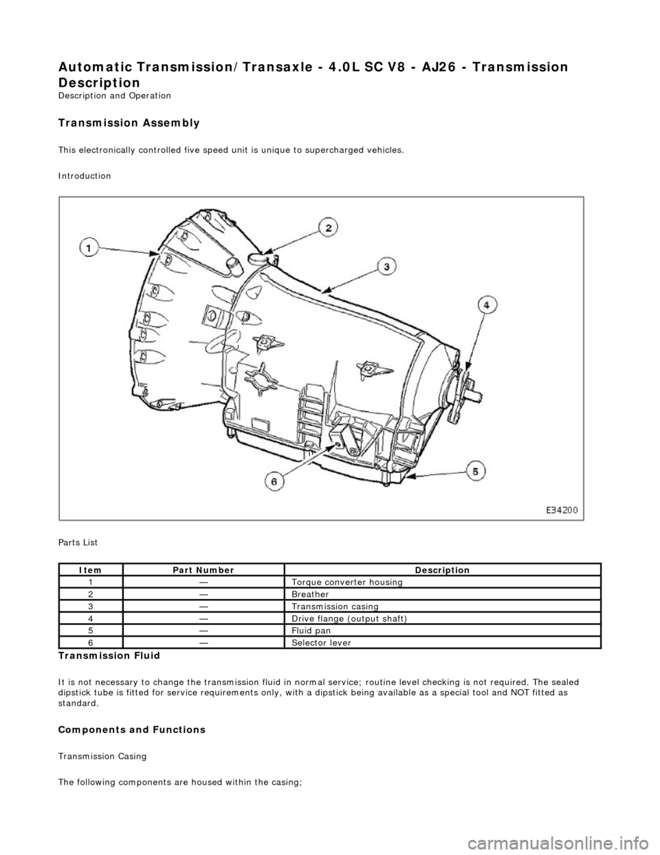
This electronically controlled five speed unit is unique to supercharged vehicles.
Introduction
Parts List
Transmission Fluid
It is not necessary to change the transmis sion fluid in normal service; routine level checking is not required. The sealed
dipstick tube is fitted for service requir ements only, with a dipstick being availa ble as a special tool and NOT fitted as
standard.
Components and Functions
Transmission Casing
The following components are housed within the casing;
ItemPart NumberDescription
1—Torque converter housing
2—Breather
3—Transmission casing
4—Drive flange (output shaft)
5—Fluid pan
6—Selector lever
Page 1431 of 2490
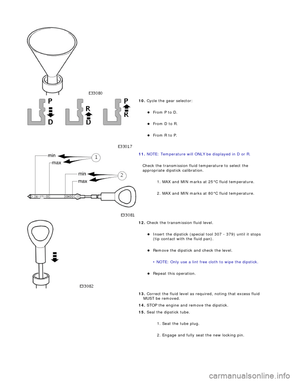
10. Cycle the gear selector:
From P to D.
From D to R.
From R to P.
11. NOTE: Temperature will ONLY be displayed in D or R.
Check the transmission fluid temperature to select the
appropriate dipstick calibration. 1. MAX and MIN marks at 25°C fluid temperature.
2. MAX and MIN marks at 80°C fluid temperature.
12. Check the transmission fluid level.
Insert the dipstick (special tool 307 - 379) until it stops
(tip contact with the fluid pan).
Remove the dipstick an d check the level.
• NOTE: Only use a lint free cloth to wipe the dipstick.
Repeat this operation.
13. Correct the fluid leve l as required, noting that excess fluid
MUST be removed.
14. STOP the engine and remove the dipstick.
15. Seal the dipstick tube.
1. Seat the tube plug.
2. Engage and fully seat the new locking pin.
Page 1440 of 2490

Automatic Transmission/Transaxle - 4.0L SC V8 - AJ26 - Transmission
Fluid Filter
In-vehicle Repair
Installation
1.
Disconnect the battery ground lead.
2. Raise the vehicle for access.
3. Remove the fluid pan, refer to Operation 44.24.04.
4. Remove the fluid filter.
Pull the filter squarely to disengage the pick-up 'O' ring
and location tang - there is NO mechanical retention.
1. Installation is the reverse of the removal procedure noting
that:
2. Renew the 'O' ring.
3. Refer to Operation 44.24.02 for fluid fill procedure.
4. Check for leaks and remove spilt fluid.
Page 1504 of 2490

Automatic Transmission/Transaxle External Controls - 4.0L SC V8 - AJ26 -
External Controls
Diagnosis and Testing
Problem Solving - Transmission Shift
Quick Reference Fault Chart
Special Tool(s)
Digital multimeter
Generic scan tool
SymptomPossible SourcesAction
Shift stuck in P Selector cable seized
*GO to 44.15.08
*
Interlock solenoid not operating
*GO to PDU
*
Interlock latch seized
Transmission faulty
*
*Mechanical check
*
Operator sequence error
*Correct the sequence
*
Vehicle rolls on P Incorrect cable adjustment
*GO 44.15.07
*
Faulty parking pawl (transmission internal)
*Mechanical check
*
R does not engageIncorrect cable adjustment
*GO to 44.15.07
*
Transmission fluid level incorrect
*GO to 44.24.02
*
N not achievedIncorrect cable adjustment
Transmission faulty
*
*GO to 44.15.07
*
D does not engageIncorrect cable adjustment *GO to 44.15.07
*
Transmission fluid level incorrect
*GO to 44.24.02
*
Transmission faulty
*Mechanical check
*
Lower ratios will not holdExcessive engine temperature
DLS fault
*
*GO to PDU
*
Shift lever position not visually correctIncorrect DLS adjustment
*GO to 44.15.07
*
Shift lever has no effect upon the
transmission and resistance cannot be
feltCable disconnected or broken
Transmission selector problem
Shift lever drive pin adrift
*
*
*Mechanical check
*
Shift lever position not align correctly
following manual selection of lower
ratiosSliding block drive pin displaced - following road debris contact
*Mechanical check. Renew the selector if
damaged, or re-align the drive pin and
sliding block
*
Shift lever detent indistinct in 3
causing poor locationDLS detent fault
*GO to Renew the DLS
*
Shift may be moved from P without
brake pedal operationInterlock latch fault
*Mechanical check
*
Solenoid permanently activated
*GO to PDU
*
Engine may be started in positions
other than P or N Incorrect cable adjustment
DLS fault
*
*GO to 44.15.07
*
Shift lever vibrationLoose selector assembly
Cable isolation fault
*
*Mechanical check
*
Noise / rattle from 'J' gateDebris in the mechanism
*Clean
*
Worn 'J' gate track gasket
allowing lever and moulding to
contact
*GO to 44.15.05
*
Page 1815 of 2490
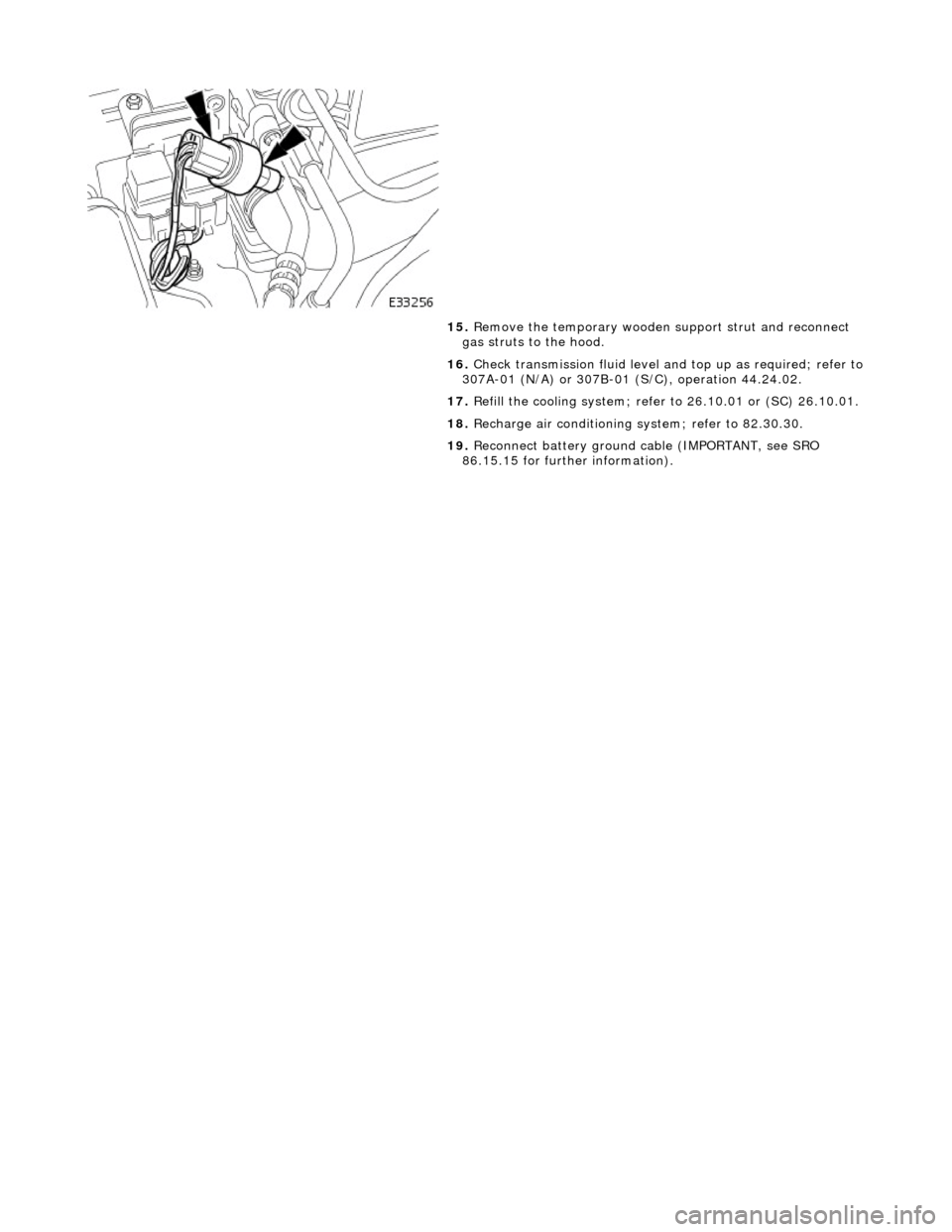
15. Remove the temporary wooden support strut and reconnect
gas struts to the hood.
16. Check transmission fluid level an d top up as required; refer to
307A-01 (N/A) or 307B-01 (S/C), operation 44.24.02.
17. Refill the cooling system; refer to 26.10.01 or (SC) 26.10.01.
18. Recharge air conditioning system; refer to 82.30.30.
19. Reconnect battery ground cable (IMPORTANT, see SRO
86.15.15 for further information).