JAGUAR X308 1998 2.G User Guide
X308 1998 2.G
JAGUAR
JAGUAR
https://www.carmanualsonline.info/img/21/7640/w960_7640-0.png
JAGUAR X308 1998 2.G User Guide
Page 1366 of 2490
Using a new gasket, install the fluid pan and tighten the twenty-
two bolts to the specified torque figure.
8. Connect the battery and fit the battery cover..
Reset the radio and the clock.
9. Refer to (44.24.02) for fluid fill procedure.
Page 1368 of 2490
Installation
1. Installation is the reverse of the removal procedure noting
that:
2. Lubricate the new 'O' rings prior to fitting.
3. Tighten the securing bolts, selector cable bracket to
transmission casing, to th e specified torque figure.
4. Connect the battery and fit the battery cover..
Reset the radio and the clock.
5. Refer to (44.24.02) for fluid fill procedure.
Page 1370 of 2490
Installation
1. Fitting a new rotary switch is the reverse of the removal
procedure noting that the fixi ngs must be tightened to the
specified torque figure.
2. Connect the battery and fit the battery cover.
Reset the radio and the clock.
Page 1374 of 2490
Installation
1.
NOTE: M5 fixing.
Connect the multiplug, install the input speed sensor and
securing bracket. Tighten the screw to the specified torque
figure.
2. NOTE: Ensure extreme clea nliness and never reuse
transmission fluid.
Using a new gasket, install the fl uid pan and tighten the twenty-
two fixings to the specified. torque figure.
3. Connect the battery and fit the battery cover..
Reset the radio and the clock.
4. Refer to (44.24.02) for fluid fill procedure.
Page 1387 of 2490
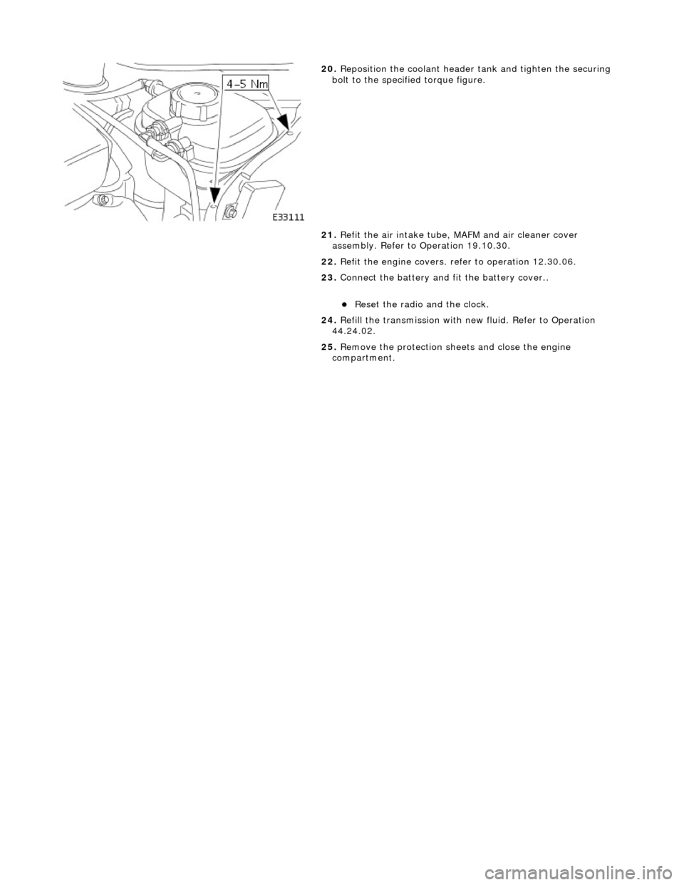
20. Reposition the coolant header tank and tighten the securing
bolt to the specified torque figure.
21. Refit the air intake tube, MAFM and air cleaner cover
assembly. Refer to Operation 19.10.30.
22. Refit the engine covers. re fer to operation 12.30.06.
23. Connect the battery and fit the battery cover..
Reset the radio and the clock.
24. Refill the transmission with new fluid. Refer to Operation
44.24.02.
25. Remove the protection sheets and close the engine
compartment.
Page 1479 of 2490
R .
7. Further installation is the reve rse of the removal procedure.
8. Connect the battery and fit the battery cover.
Reset the radio and the clock.
Page 1483 of 2490
moving the set position of either the shift lever or the selector lever.
3. Tighten the locknuts to the specified torque figure
4. Verify the N setting.
11. Further installation is the reve rse of the removal procedure.
12. Connect the battery and fit the battery cover.
Reset the radio and the clock.
Page 1485 of 2490
3. Connect the battery and fit the battery cover.
Reset the radio and the clock.
Page 1491 of 2490
Automatic Transmission/Transaxle External Controls - 4.0L NA V8 -
AJ27/3.2L NA V8 - AJ 26 - Selector Lever Indicator Assembly
Removal and Installation
Removal
Installation
1. Disconnect battery ground cable.
Remove the battery cover.
2. Remove the selector lever knob, 44.15.06.
3. Remove the J-gate surround, Section 501-05.
4. Remove the console finisher ve neer panel, Section 501-12.
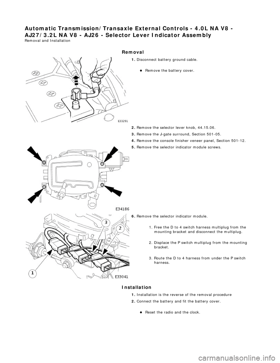
5. Remove the selector indicator module screws.
6. Remove the selector indicator module.
1. Free the D to 4 switch harness multiplug from the mounting bracket and disc onnect the multiplug.
2. Displace the P switch multiplug from the mounting bracket.
3. Route the D to 4 harnes s from under the P switch
harness.
1. Installation is the revers e of the removal procedure
2. Connect the battery and fit the battery cover.
Reset the radio and the clock.
Page 1492 of 2490
Automatic Transmission/Transaxle External Controls - 4.0L NA V8 -
AJ27/3.2L NA V8 - AJ26 - Se lector Lever Indicator Disc
Removal and Installation
Removal
Installation
1. Disconnect battery ground cable.
Remove the battery cover.
2. Remove the selector indicator module; 44.15.14.
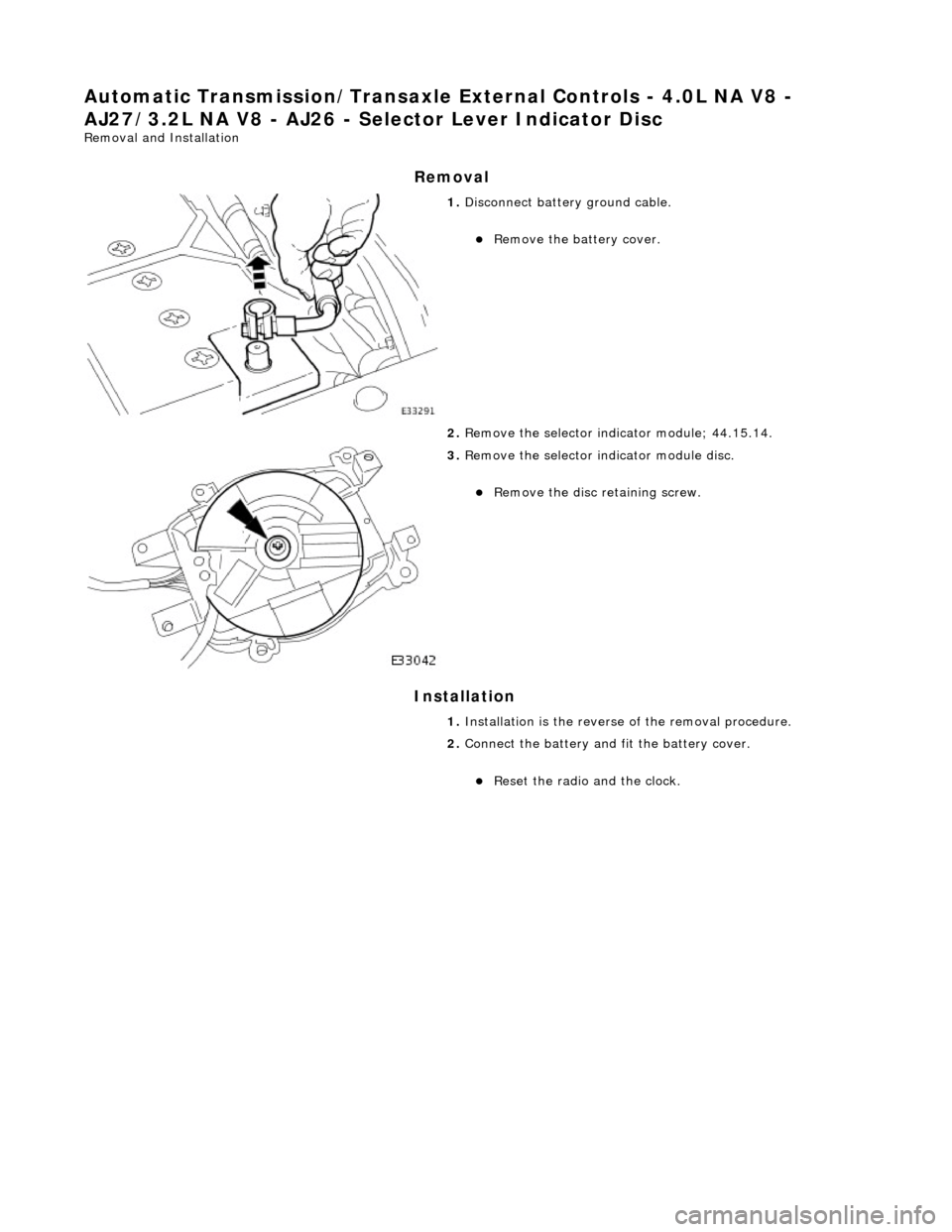
3. Remove the selector indicator module disc.
Remove the disc retaining screw.
1. Installation is th e reverse of the re moval procedure.
2. Connect the battery and fit the battery cover.
Reset the radio and the clock.


