diagram JAGUAR X308 1998 2.G User Guide
[x] Cancel search | Manufacturer: JAGUAR, Model Year: 1998, Model line: X308, Model: JAGUAR X308 1998 2.GPages: 2490, PDF Size: 69.81 MB
Page 1022 of 2490
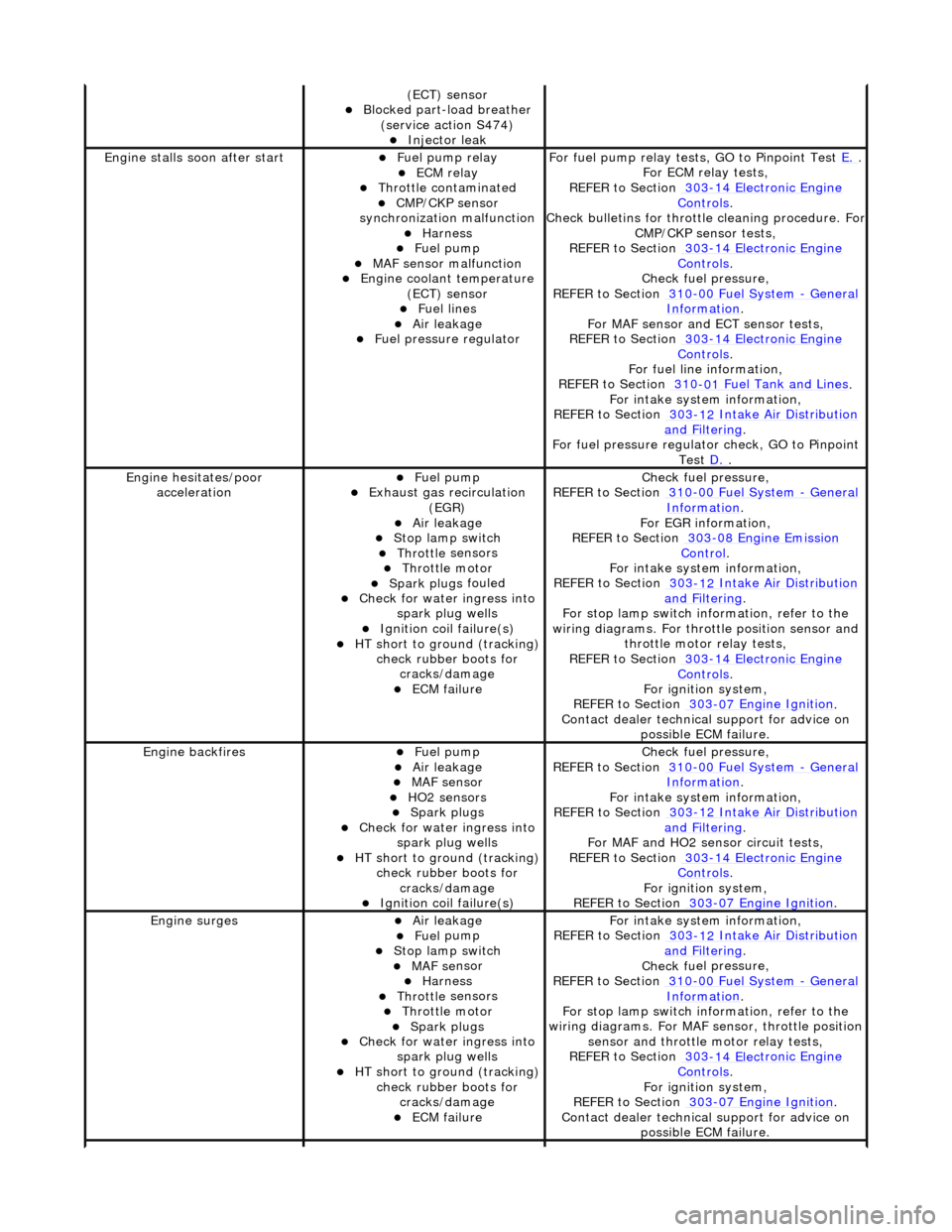
(ECT) se
nsor
Blocked part-load breather
(s
ervice action S474)
Injec
t
or leak
Engine stalls
soon
after start
F
u
el pump relay
ECM relay Thr
o
ttle contaminated
CMP/CKP sen
s
or
synchronization malfunction
Harness Fuel
pump
MAF
s
ensor malfunction
Engine coolan
t
temperature
(ECT) sensor
Fue l
lines
Air leakage Fu
el pressure regulator
F
o
r fuel pump relay tests,
GO to Pinpoint Test E.
.
F or ECM
relay tests,
REFER to Section 303
-14 Elec tronic En
gine
Controls.
Check bull etins for throttl
e cleaning procedure. For
CMP/CKP sensor tests,
REFER to Section 303
-14 Elec tronic En
gine
Controls.
Chec k fu
el pressure,
REFER to Section 310
-00 Fu
el System
- Ge
n
eral
Informati
o
n
.
F or MAF sensor and
ECT sensor tests,
REFER to Section 303
-14 Electronic En
gine
Controls.
For fuel l
ine information,
REFER to Section 310
-01
Fuel Tank and Lines
.
F or i
ntake system information,
REFER to Section 303
-1 2
Intake Air Distribution
and F
ilt
ering
.
F o
r fuel pressure regulato
r check, GO to Pinpoint
Test D.
.
Engine h e
sitates/poor
acceleration
Fue l
pump
Exhaus
t gas
recirculation
(EGR)
Air leakage Stop lamp swi t
ch
Throttl
e
sensors
Throttl
e
motor
Spark plugs
fouled
Check f
o
r water ingress into
spark plug wells
Ignition coil fail
ure(s)
HT sho
rt to ground (tracking)
check rubber
boots for
cracks/damage
ECM failu r
e
Chec
k fu
el pressure,
REFER to Section 310
-00 Fu
el System
- Ge
n
eral
Informati
o
n
.
F o
r EGR information,
REFER to Section 303
-08 En gin
e Emission
Control.
F or i
ntake system information,
REFER to Section 303
-1 2
Intake Air Distribution
and F
ilt
ering
.
F or stop l
amp switch in
formation, refer to the
wiring diagrams. For throttle position sensor and throttle motor relay tests,
REFER to Section 303
-14 Elec tronic En
gine
Controls.
For ign i
tion system,
REFER to Section 303
-07 En
gine Ignition
.
Contact dealer techn i
cal
support for advice on
possible ECM failure.
Engine ba ckfiresFuel
pump
Air leakage MAF s
e
nsor
HO2 sensors Spark plugs
Check fo
r water ingress into
spark plug wells
HT short to ground (tracking) check rubber
boots for
cracks/damage
Ignition coil fail
ure(s)
Chec
k fu
el pressure,
REFER to Section 310
-00 Fu
el System
- Ge
n
eral
Informati
o
n
.
F or i
ntake system information,
REFER to Section 303
-1 2
Intake Air Distribution
and F
ilt
ering
.
For MAF and HO2
sensor circuit tests,
REFER to Section 303
-14 Electronic En
gine
Controls.
For igni
tion system,
REFER to Section 303
-07 En
gine Ignition
.
Engine
s
urges
Air leakage Fue
l
pump
Stop lamp swi
t
ch
MAF s
e
nsor
Harness Throttl
e
sensors
Throttl
e
motor
Spark plugs
Check fo
r water ingress into
spark plug wells
HT sho rt to ground (tracking)
check rubber
boots for
cracks/damage
ECM failu r
e
F
or i
ntake system information,
REFER to Section 303
-1 2
Intake Air Distribution
and F
ilt
ering
.
Chec k fu
el pressure,
REFER to Section 310
-00 Fu
el System
- Gen
e
ral
Informati
o
n
.
F or stop l
amp switch in
formation, refer to the
wiring diagrams. For MAF se nsor, throttle position
sensor and throttle motor relay tests,
REFER to Section 303
-14 Elec tronic En
gine
Controls.
For ign i
tion system,
REFER to Section 303
-07 En
gine Ignition
.
Contact dealer techn i
cal
support for advice on
possible ECM failure.
Page 1029 of 2490
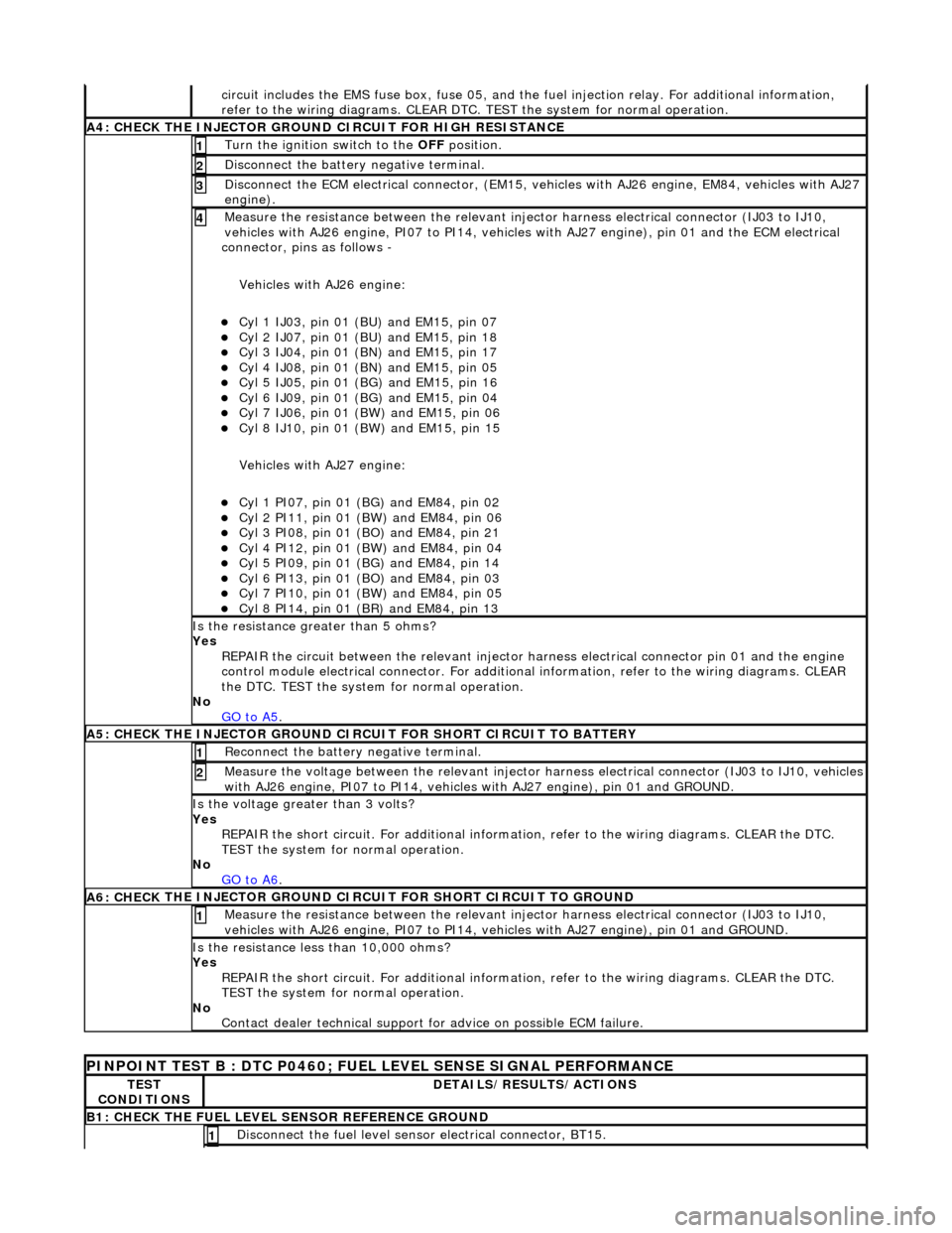
ci
rcuit includes the EMS fuse box,
fuse 05, and the fuel injection relay. For additional information,
refer to the wiring diagrams. CLEAR DTC. TEST the system for normal operation.
A4: CHECK
THE INJECTOR GROUND
CIRCUIT FOR HIGH RESISTANCE
Turn the ignition swi
tch to the OFF
position.
1
Di
sconnect the battery negative terminal.
2
D
isconnect the ECM electrical connector, (EM15, vehi
cles with AJ26 engine, EM84, vehicles with AJ27
engine).
3
Meas
ure the resistance between the relevant injector harness electrical connector (IJ03 to IJ10,
vehicles with AJ26 engine, PI07 to PI14, vehicles with AJ27 engine), pin 01 and the ECM electrical
connector, pins as follows -
Vehicles with AJ26 engine:
Cy
l 1 IJ03, pin 01 (BU) and EM15, pin 07
Cy
l 2 IJ07, pin 01 (BU) and EM15, pin 18
Cy
l 3 IJ04, pin 01 (BN) and EM15, pin 17
Cy
l 4 IJ08, pin 01 (BN) and EM15, pin 05
Cy
l 5 IJ05, pin 01 (BG) and EM15, pin 16
Cy
l 6 IJ09, pin 01 (BG) and EM15, pin 04
Cy
l 7 IJ06, pin 01 (BW) and EM15, pin 06
Cy
l 8 IJ10, pin 01 (BW) and EM15, pin 15
Vehicles with AJ27 engine:
Cy
l 1 PI07, pin 01 (B
G) and EM84, pin 02
Cy
l 2 PI11, pin 01 (BW) and EM84, pin 06
Cy
l 3 PI08, pin 01 (BO) and EM84, pin 21
Cy
l 4 PI12, pin 01 (BW) and EM84, pin 04
Cy
l 5 PI09, pin 01 (B
G) and EM84, pin 14
Cy
l 6 PI13, pin 01 (BO) and EM84, pin 03
Cy
l 7 PI10, pin 01 (BW) and EM84, pin 05
Cy
l 8 PI14, pin 01 (BR) and EM84, pin 13
4
Is th
e resistance greater than 5 ohms?
Yes REPAIR the circuit between the relevant injector harness electrical connector pin 01 and the engine
control module electrical connecto r. For additional information, refer to the wiring diagrams. CLEAR
the DTC. TEST the system for normal operation.
No GO to A5
.
A5: CHECK
THE INJECTOR GROUND CI
RCUIT FOR SHORT CIRCUIT TO BATTERY
R
econnect the battery negative terminal.
1
Meas
ure the voltage between the relevant injector harness electrical connector (IJ03 to IJ10, vehicles
with AJ26 engine, PI07 to PI14, vehicles with AJ27 engine), pin 01 and GROUND.
2
Is th
e voltage greater than 3 volts?
Yes REPAIR the short circuit. For addi tional information, refer to the wiring diagrams. CLEAR the DTC.
TEST the system for normal operation.
No GO to A6
.
A6: CHECK
THE INJECTOR GROUND CI
RCUIT FOR SHORT CIRCUIT TO GROUND
Meas
ure the resistance between the relevant injector harness electrical connector (IJ03 to IJ10,
vehicles with AJ26 engine, PI07 to PI14, vehicles with AJ27 engine), pin 01 and GROUND.
1
Is
the resistance less than 10,000 ohms?
Yes REPAIR the short circuit. For addi tional information, refer to the wiring diagrams. CLEAR the DTC.
TEST the system for normal operation.
No Contact dealer technical support for advice on possible ECM failure.
P
INPOINT TEST B : DTC P0460; FUEL
LEVEL SENSE SIGNAL PERFORMANCE
TE
ST
CONDITIONS
D
ETAILS/RESULTS/ACTIONS
B1: CHECK
THE FUEL LEVEL SENSOR REFERENCE GROUND
Di
sconnect the fuel level sensor electrical connector, BT15.
1
Page 1030 of 2490
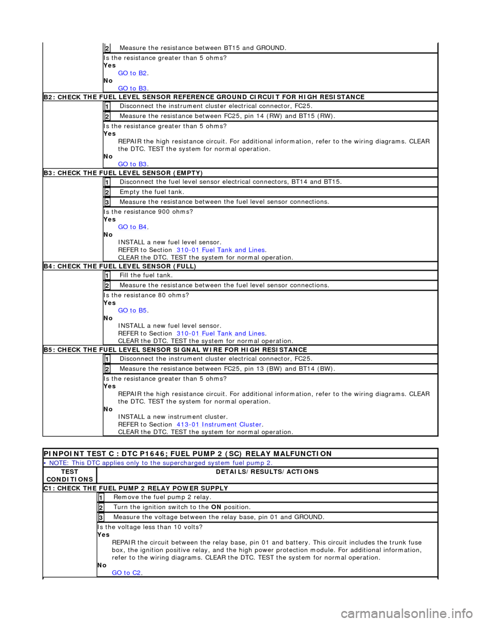
Measure t
he resistance
between BT15 and GROUND.
2
Is the res
istance greater than 5 ohms?
Yes GO to B2
.
No
GO to B3
.
B2: CHECK THE FUEL
LEVEL SENSOR REFERE
NCE GROUND CIRCUIT FOR HIGH RESISTANCE
Disc
onnect the instrument cluster electrical connector, FC25.
1
Meas
ure t
he resistance between FC25, pin 14 (RW) and BT15 (RW).
2
Is the res
istance greater than 5 ohms?
Yes REPAIR the high resistance circui t. For additional information, refer to the wiring diagrams. CLEAR
the DTC. TEST the system for normal operation.
No GO to B3
.
B3: CHECK THE FUEL
LEVEL SENSOR (EMPTY)
Di
sc
onnect the fuel level sensor electrical connectors, BT14 and BT15.
1
Empty the fuel
tank. 2
Measure t
he resistance between the
fuel level sensor connections.
3
Is t
he resistance 900 ohms?
Yes GO to B4
.
No
INST
ALL a new fuel level sensor.
REFER to Section 310
-0 1
Fuel Tank and Lines
.
CLEAR t h
e DTC. TEST the system for normal operation.
B4:
CHECK
THE FUEL LEVEL SENSOR (FULL)
Fi
ll
the fuel tank.
1
Meas
ure t
he resistance between the
fuel level sensor connections.
2
Is
the resistance 80 ohms?
Yes GO to B5
.
No
INST
ALL a new fuel level sensor.
REFER to Section 310
-0 1
Fuel Tank and Lines
.
CLEAR t h
e DTC. TEST the system for normal operation.
B
5
: CHECK THE FUEL LEVEL SENSOR SIGNAL WIRE FOR HIGH RESISTANCE
Di
sc
onnect the instrument cluster electrical connector, FC25.
1
Meas
ure t
he resistance between FC25, pin 13 (BW) and BT14 (BW).
2
Is th
e res
istance greater than 5 ohms?
Yes REPAIR the high resistance circui t. For additional information, refer to the wiring diagrams. CLEAR
the DTC. TEST the system for normal operation.
No INSTALL a new instrument cluster.
REFER to Section 413
-01
Instrume
nt Cluster
.
CLEAR t h
e DTC. TEST the system for normal operation.
P
INPOINT TEST C : DTC P1646; FU
EL PUMP 2 (SC) RELAY MALFUNCTION
•
NO
TE: This DTC applies only to the
supercharged system fuel pump 2.
TES
T
CONDITIONS
D E
TAILS/RESULTS/ACTIONS
C
1
: CHECK THE FUEL PUMP 2 RELAY POWER SUPPLY
R
e
move the fuel pump 2 relay.
1
Turn the ignition swi
t
ch to the
ON position.
2
Meas
ure t
he voltage between the
relay base, pin 01 and GROUND.
3
Is the volt
age less than 10 volts?
Yes REPAIR the circuit between the rela y base, pin 01 and battery. This circuit includes the trunk fuse
box, the ignition positive relay, and the high power protection module. For additional information,
refer to the wiring diagrams. CLEAR the DTC. TEST the system for normal operation.
No GO to C2
.
Page 1031 of 2490
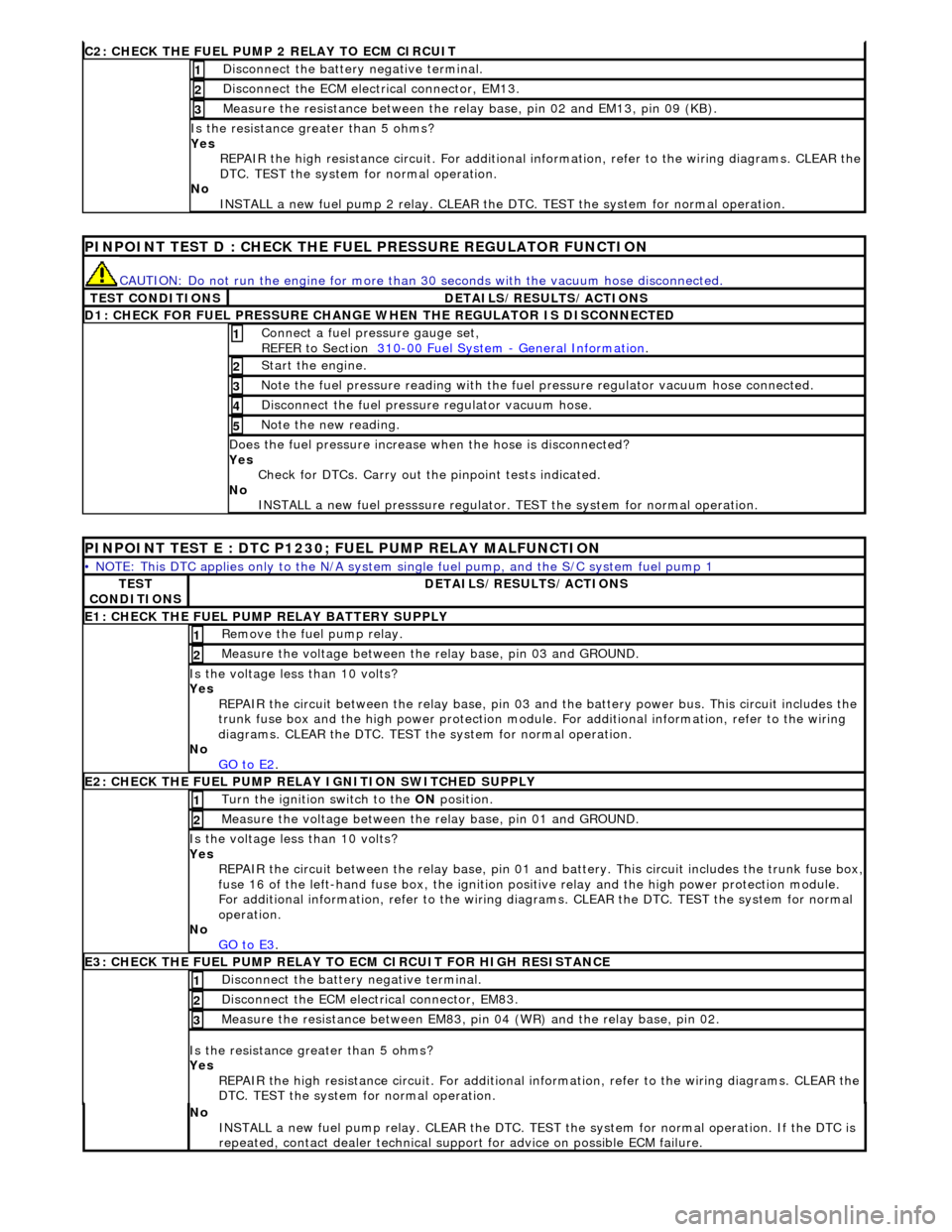
C2: CHECK THE FUEL
PUMP 2 RELAY TO ECM CIRCUIT
Di
sconnect the battery negative terminal.
1
D
isconnect the ECM electrical connector, EM13.
2
Meas
ure the resistance between the rela
y base, pin 02 and EM13, pin 09 (KB).
3
Is th
e resistance greater than 5 ohms?
Yes REPAIR the high resistance circuit. For additional information, refer to the wiring diagrams. CLEAR the
DTC. TEST the system for normal operation.
No INSTALL a new fuel pump 2 relay. CLEAR the DT C. TEST the system for normal operation.
P
INPOINT TEST D : CHECK THE FUEL PRESSURE REGULATOR FUNCTION
CAUTI
ON: Do not run the engine for more than
30 seconds with the vacuum hose disconnected.
T
EST CONDITIONS
D
ETAILS/RESULTS/ACTIONS
D
1: CHECK FOR FUEL PRESSURE CHANGE
WHEN THE REGULATOR IS DISCONNECTED
Connect a
fuel pressure gauge set,
REFER to Section 310
-00
Fuel System
-
General Informati
on
. 1
St
art the engine.
2
N
ote the fuel pressure readin
g with the fuel pressure regu lator vacuum hose connected.
3
Di
sconnect the fuel pressu
re regulator vacuum hose.
4
N
ote the new reading.
5
Doe
s the fuel pressure increase when the hose is disconnected?
Yes Check for DTCs. Carry out the pinpoint tests indicated.
No INSTALL a new fuel presssure regulator. TEST the system for normal operation.
P
INPOINT TEST E : DTC P1230;
FUEL PUMP RELAY MALFUNCTION
•
NOTE: This DTC applies only to the N/A system si
ngle fuel pump, and the S/C system fuel pump 1
TE
ST
CONDITIONS
D
ETAILS/RESULTS/ACTIONS
E1
: CHECK THE FUEL PUMP
RELAY BATTERY SUPPLY
R
emove the fuel pump relay.
1
Meas
ure the voltage between the
relay base, pin 03 and GROUND.
2
Is th
e voltage less than 10 volts?
Yes REPAIR the circuit between the rela y base, pin 03 and the battery power bus. This circuit includes the
trunk fuse box and the high power protection module . For additional information, refer to the wiring
diagrams. CLEAR the DTC. TEST th e system for normal operation.
No GO to E2
.
E2
: CHECK THE FUEL PUMP RELAY IGNITION SWITCHED SUPPLY
Turn the ignition swi
tch to the
ON position.
1
Meas
ure the voltage between the
relay base, pin 01 and GROUND.
2
Is th
e voltage less than 10 volts?
Yes REPAIR the circuit between the rela y base, pin 01 and battery. This circuit includes the trunk fuse box,
fuse 16 of the left-hand fuse box, the ignition po
sitive relay and the high power protection module.
For additional information, refer to the wiring diagrams. CLEAR the DTC. TEST the system for normal
operation.
No GO to E3
.
E3
: CHECK THE FUEL PUMP RELAY TO
ECM CIRCUIT FOR HIGH RESISTANCE
Di
sconnect the battery negative terminal.
1
D
isconnect the ECM electrical connector, EM83.
2
Meas
ure the resistance between EM83, pi
n 04 (WR) and the relay base, pin 02.
3
Is th
e resistance greater than 5 ohms?
Yes REPAIR the high resistance circuit. For additional information, refer to the wiring diagrams. CLEAR the
DTC. TEST the system for normal operation.
No
INSTALL a new fuel pump relay. CLEAR the DTC. TEST the system for normal operation. If the DTC is
repeated, contact dealer technical support for advice on possible ECM failure.
Page 1064 of 2490
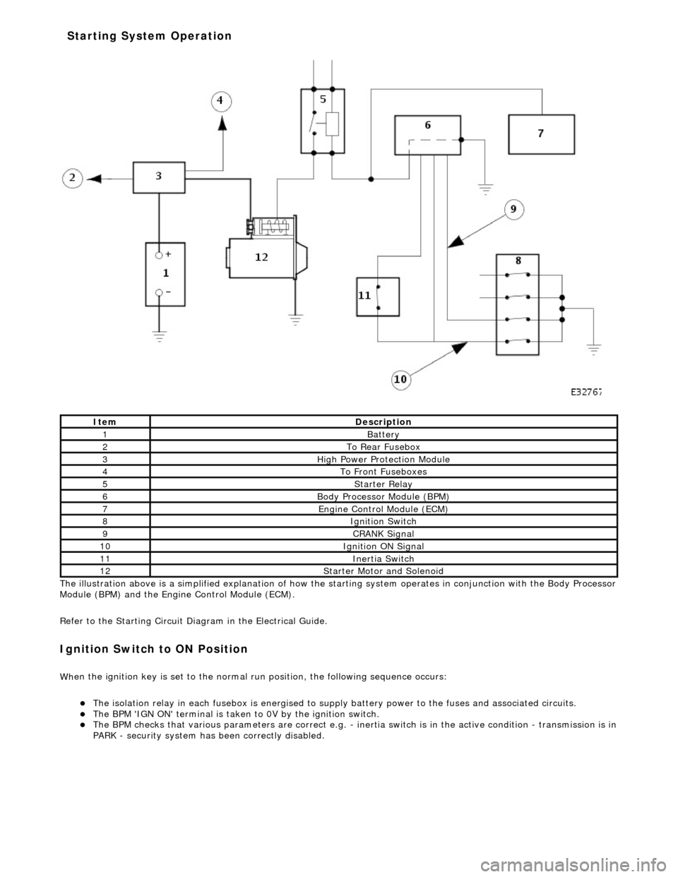
The il
lustration above is a simplified expl
anation of how the starting system operates in conjunction with the Body Processor
Module (BPM) and the Engine Control Module (ECM).
Refer to the Starting Circuit Diagram in the Electrical Guide.
I g
nition Switch to ON Position
W
h
en the ignition key is set to the normal run position, the following sequence occurs:
The
is
olation relay in each fusebox is
energised to supply battery power to the fuses and associated circuits.
The BPM 'IGN
ON' terminal
is taken to 0V by the ignition switch.
The BPM
checks that various parameters are correct e.g. -
inertia switch is in the active condition - transmission is in
PARK - security system has been correctly disabled.
It e
m
De
scr
iption
1Batt
ery
2To Re ar
Fusebox
3Hi
gh Power Pr
otection Module
4To Front
Fu
seboxes
5Starter Re
lay
6Body Processor M
odule (BPM)
7Engine
C
ontrol Module (ECM)
8Ignition Switch
9CRANK Signal
10Ignition ON Signal
11Inertia Switch
12St
arte
r Motor and Solenoid
Starting System Operation
Page 1065 of 2490
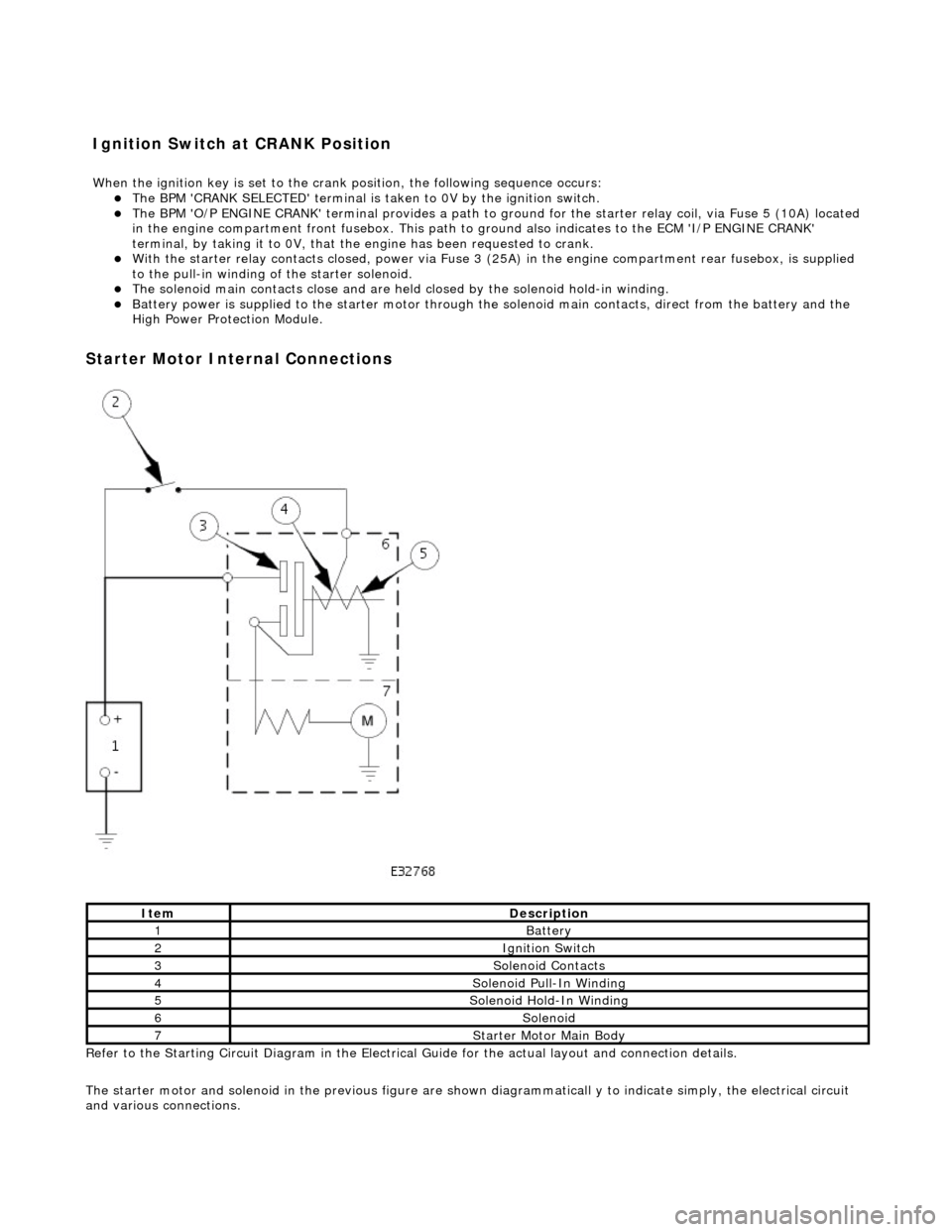
The BPM
'CRANK SELECTED' terminal is ta
ken to 0V by the ignition switch.
The BPM
'O/P ENGINE CRANK' terminal pr
ovides a path to ground for the starte r relay coil, via Fuse 5 (10A) located
in the engine compartment front fusebo x. This path to ground also indicates to the ECM 'I/P ENGINE CRANK'
terminal, by taking it to 0V, that the engine has been requested to crank.
Wi
th the starter relay contacts closed,
power via Fuse 3 (25A) in the engine compartment rear fusebox, is supplied
to the pull-in winding of the starter solenoid.
The s
olenoid main contacts close and are held
closed by the solenoid hold-in winding.
Battery power is supplied
to
the starter motor through the solenoid main contacts, direct from the battery and the
High Power Protection Module.
Starter
Motor Internal Connections
Re
fer to the Starting Circuit Diagram in the Electrical
Guide for the actual layout and connection details.
The starter motor and solenoid in the previous figure are shown diagrammaticall y to indicate simply, the electrical circuit
and various connections.
It
em
De
scription
1Batt
ery
2Ignition Switch
3So
lenoid Contacts
4So
lenoid Pull-In Winding
5So
lenoid Hold-In Winding
6So
lenoid
7St
arter Motor Main Body
I
gnition Switch at CRANK Position
W
hen the ignition key is set to the crank position, the following sequence occurs:
Page 1068 of 2490
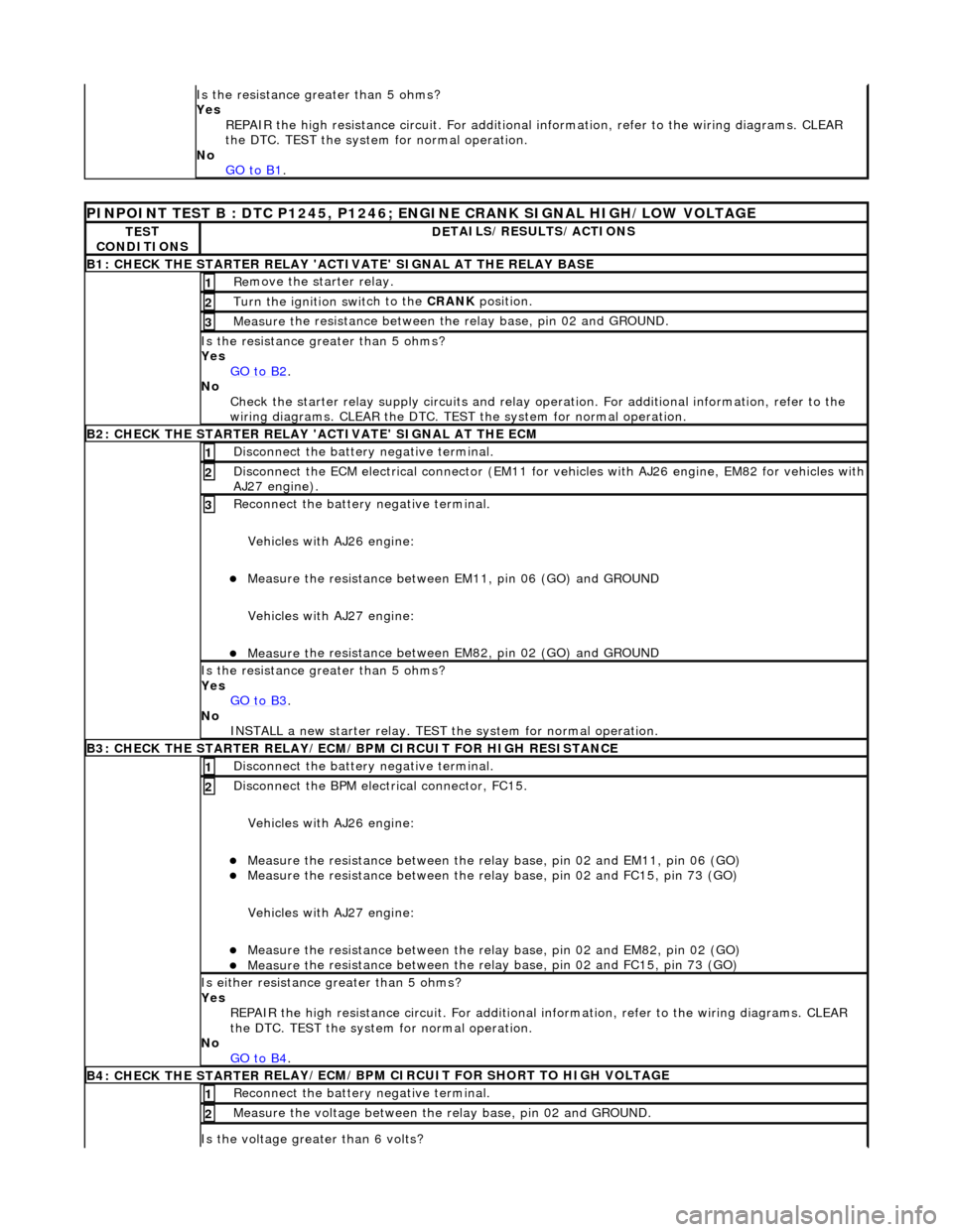
Is the res
istance greater than 5 ohms?
Yes REPAIR the high resistance circui t. For additional information, refer to the wiring diagrams. CLEAR
the DTC. TEST the system for normal operation.
No GO to B1
.
PINPOINT TES
T B : DTC P1245, P1246; ENGINE CRANK SIGNAL HIGH/LOW VOLTAGE
TE
S
T
CONDITIONS
D E
TAILS/RESULTS/ACTIONS
B1: CHECK
THE STARTER
RELAY 'ACTIV
ATE' SIGNAL AT THE RELAY BASE
Re
move the starter relay.
1
Turn the ignition swi
t
ch to the CRANK
position.
2
Measure t
he resistance between th
e relay base, pin 02 and GROUND.
3
Is the res
istance greater than 5 ohms?
Yes GO to B2
.
No Check t
he starter relay supply circui
ts and relay operation. For additi onal information, refer to the
wiring diagrams. CLEAR the DTC. TEST the system for normal operation.
B2: CHECK THE STARTER
RELAY 'A
CTIVATE' SIGNAL AT THE ECM
Disc
onnect the battery negative terminal.
1
D
i
sconnect the ECM electrical connector (EM11 for vehicles with AJ26 engine
, EM82 for vehicles with
AJ27 engine).
2
R e
connect the battery negative terminal.
Vehicles with AJ26 engine:
Meas ure t
he resistance between EM11, pin 06 (GO) and GROUND
Vehicles with AJ27 engine:
Meas ure t
he resistance between EM82, pin 02 (GO) and GROUND
3
Is th
e res
istance greater than 5 ohms?
Yes GO to B3
.
No
IN
STALL a new starter relay. TEST
the system for normal operation.
B3: CHECK THE STARTER
RELAY/ECM/BPM CIRCUIT FOR HIGH RESISTANCE
Di sc
onnect the battery negative terminal.
1
Disc
onne
ct the BPM electrical connector, FC15.
Vehicles with AJ26 engine:
Meas ure t
he resistance between the relay
base, pin 02 and EM11, pin 06 (GO)
Measure t
he resistance between the relay
base, pin 02 and FC15, pin 73 (GO)
Vehicles with AJ27 engine:
Meas ure t
he resistance between the relay
base, pin 02 and EM82, pin 02 (GO)
Measure t
he resistance between the relay
base, pin 02 and FC15, pin 73 (GO)
2
Is either resistance greater
than 5 ohms?
Yes REPAIR the high resistance circui t. For additional information, refer to the wiring diagrams. CLEAR
the DTC. TEST the system for normal operation.
No GO to B4
.
B4: CHECK THE STARTER
RE
LAY/ECM/BPM CIRCUIT FOR SHORT TO HIGH VOLTAGE
Re
connect the battery negative terminal.
1
Meas
ure t
he voltage between the
relay base, pin 02 and GROUND.
2
Is the volt
age greater than 6 volts?
Page 1069 of 2490
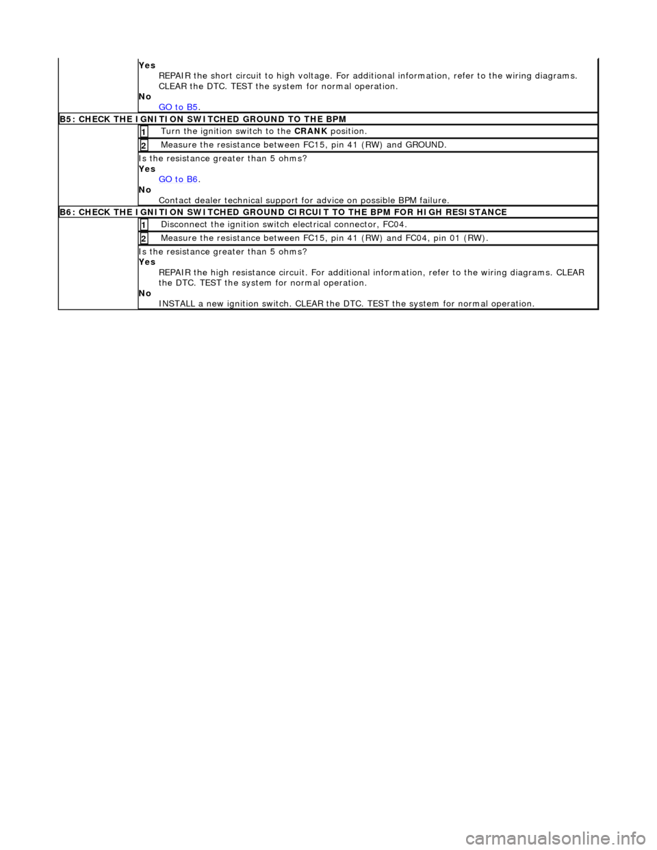
Yes
REPAIR the short circuit to high voltage. For addi tional information, refer to the wiring diagrams.
CLEAR the DTC. TEST the syst em for normal operation.
No GO to B5
.
B5: CHECK
THE IGNITION SWITCHED GROUND TO THE BPM
Turn the ignition swi
tch to the CRANK
position.
1
Meas
ure the resistance between FC15, pin 41 (RW) and GROUND.
2
Is th
e resistance greater than 5 ohms?
Yes GO to B6
.
No
Contact dealer technical support fo r advice on possible BPM failure.
B6: CHECK
THE IGNITION SWIT
CHED GROUND CIRCUIT TO THE BPM FOR HIGH RESISTANCE
Di
sconnect the ignition switch electrical connector, FC04.
1
Meas
ure the resistance between FC15,
pin 41 (RW) and FC04, pin 01 (RW).
2
Is th
e resistance greater than 5 ohms?
Yes REPAIR the high resistance circui t. For additional information, refer to the wiring diagrams. CLEAR
the DTC. TEST the system for normal operation.
No INSTALL a new ignition switch. CLEAR the DTC. TEST the system for normal operation.
Page 1073 of 2490

Engine Igni
tion -
Engine Ignition
Description an
d Operation
I
gnition coil and spark plug reference
Any positional r
eferences are base
d upon the following convention:
viewing from the driving position, the right-hand cylinder bank is designated bank 1 (A on circuit diagrams) and the left-
hand cylinder bank as bank 2 (B on circuit diagrams).
The cylinder bores of each bank are number ed 1 to 4, from the front of the vehicle.
Ig
nition System
Th
e ignition system provides timing cont
rol in accordance with the engine mana gement strategy and powertrain sensor
inputs; the system consists of:
engine
control module
igni
tion coils supply relay
ignit
ion control modules
igni
tion coils
spark plu
gs
Engine Control Module (ECM)
pr
ovides triggering for the ignition control modules
to control individual firing of the spark plugs
supplies ground for
the igni
tion coils supply relay
I
gnition Coils Supply Relay
The
ignition coils supply relay is located
in the engine and transmission control mo dule compartment; refer to Relay Details
in Electrical Wiring and Circuit Protection, Section 418-01.
The ECM switches a ground to the coil of the ignition coils supply relay; the relay energizes and switches a 12v supply to the
ignition control modules and the ignition coils.
I
gnition Control Modules
Page 1076 of 2490
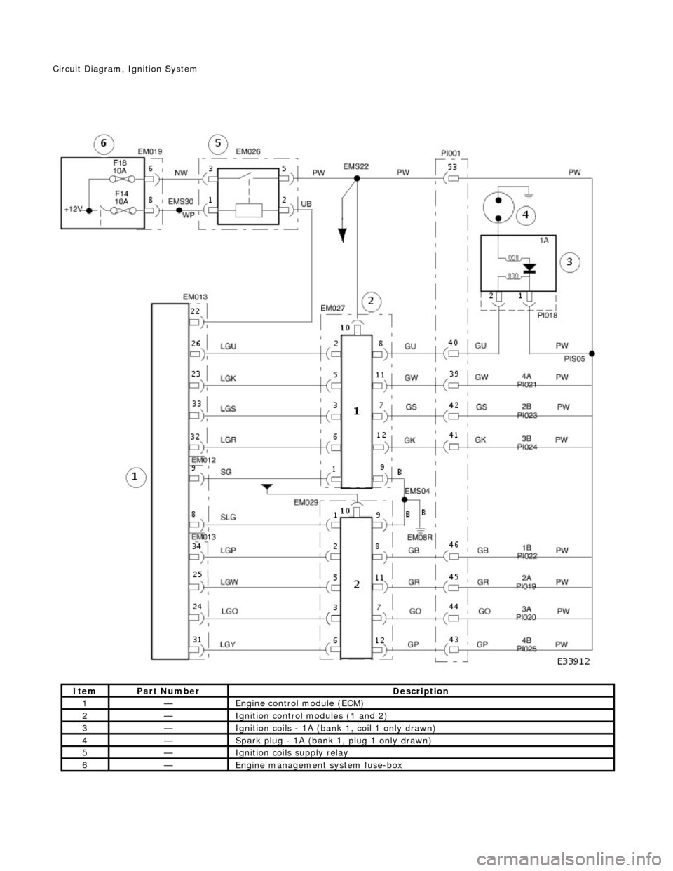
It e
m
Par
t
Number
De
scr
iption
1—Engine
control module (E
CM)
2—Ignition control
modules (1 and 2)
3—Igniti
on coils - 1A (bank 1, coil 1 only drawn)
4—Spark
plug - 1
A (bank 1, plug 1 only drawn)
5—Igni
ti
on coils supply relay
6—Engine
management system fuse-box
Ci
rcui
t Diagram,
Ignition System