diagram JAGUAR X308 1998 2.G Owner's Manual
[x] Cancel search | Manufacturer: JAGUAR, Model Year: 1998, Model line: X308, Model: JAGUAR X308 1998 2.GPages: 2490, PDF Size: 69.81 MB
Page 1084 of 2490
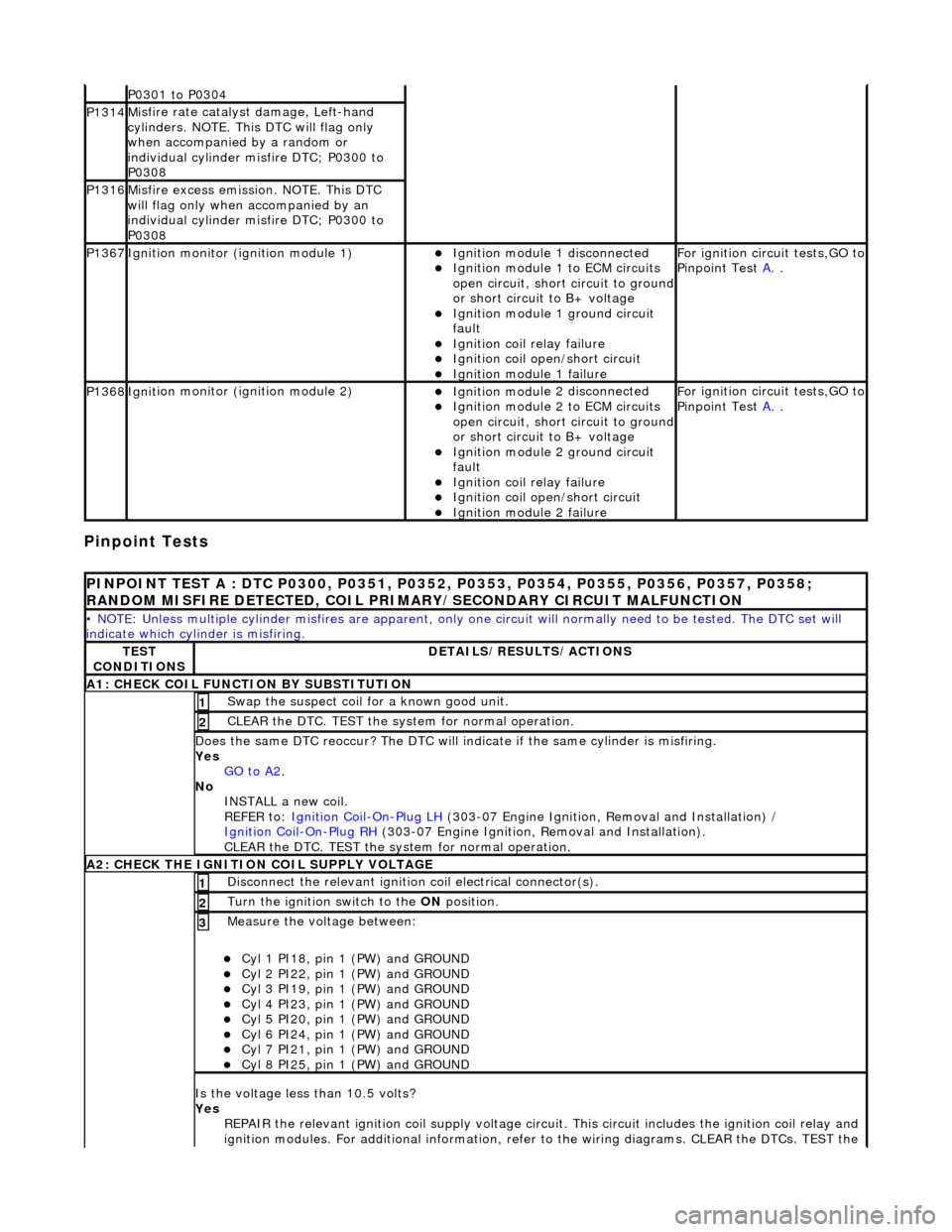
Pinpoint Tests
P0301 t
o P0304
P1314M
i
sfire rate catalyst damage, Left-hand
cylinders. NOTE. This DTC will flag only
when accompanied by a random or
individual cylinder misfire DTC; P0300 to
P0308
P1316M i
sfire excess emission. NOTE. This DTC
will flag only when accompanied by an
individual cylinder misfire DTC; P0300 to
P0308
P1367Ignit i
on monitor (ignition module 1)
Ignition modu
le
1 disconnected
Ignition modul e
1 to ECM circuits
open circuit, short circuit to ground
or short circuit to B+ voltage
Ignition modul e
1 ground circuit
fault
Ignition coil relay fai
lure
Ignition coil open/short
circuit
Ignition module
1 failure
F
o
r ignition circuit tests,GO to
Pinpoint Test A.
.
P1368Igniti
on monitor (ignition module 2)
Ignition modu
le
2 disconnected
Ignition modul e
2 to ECM circuits
open circuit, short circuit to ground
or short circuit to B+ voltage
Ignition modul e
2 ground circuit
fault
Ignition coil relay fai
lure
Ignition coil
open/short
circuit
Ignition modul
e
2 failure
F
o
r ignition circuit tests,GO to
Pinpoint Test A.
.
PINPOINT TES
T A : DTC P0300, P0351, P0352, P0353, P0354, P0355, P0356, P0357, P0358;
RANDOM MISFIRE DETECTED, COIL PRIMARY/SECONDARY CIRCUIT MALFUNCTION
• NO
TE: Unless multiple cylinder misfires are apparent, only on
e circuit will normally need to be tested. The DTC set will
indicate which cylinder is misfiring.
TE S
T
CONDITIONS
D E
TAILS/RESULTS/ACTIONS
A1
: CH
ECK COIL FUNCTI
ON BY SUBSTITUTION
Swap the suspect coi l
for a known good unit.
1
CLEAR t
h
e DTC. TEST the syst
em for normal operation.
2
Do
es the same DTC reoccur? The DTC will indicate if the same cylinder is misfiring.
Yes GO to A2
.
No
INST
ALL a new coil.
REFER to: Ignition Coil
-On-Plug
LH
(30
3-07 Engine Ignition, Removal and Installation) /
Ignition Coil
-On-Plu g
RH
(30
3-07 Engine Ignition, Removal and Installation).
CLEAR the DTC. TEST the system for normal operation.
A2: CHECK THE IGNIT
ION COIL SUPPLY VOLTAGE
Disc
onne
ct the relevant ignition
coil electrical connector(s).
1
Turn the ignition swit
ch to the ON
position.
2
Measure the voltage between:
Cyl 1 PI18, pin
1 (PW) and GROUND
Cy
l 2 PI22, pin
1 (PW) and GROUND
Cy
l 3 PI19, pin
1 (PW) and GROUND
Cy
l 4 PI23, pin
1 (PW) and GROUND
Cy
l 5 PI20, pin
1 (PW) and GROUND
Cy
l 6 PI24, pin
1 (PW) and GROUND
Cy
l 7 PI21, pin
1 (PW) and GROUND
Cy
l 8 PI25, pin
1 (PW) and GROUND
3
Is
t
he voltage less than 10.5 volts?
Yes REPAIR the relevant ignition coil su pply voltage circuit. This circuit includes the ignition coil relay and
ignition modules. For additional information, refer to the wiring diagrams. CLEAR the DTCs. TEST the
Page 1085 of 2490
system fo
r normal operation.
No GO to A3
.
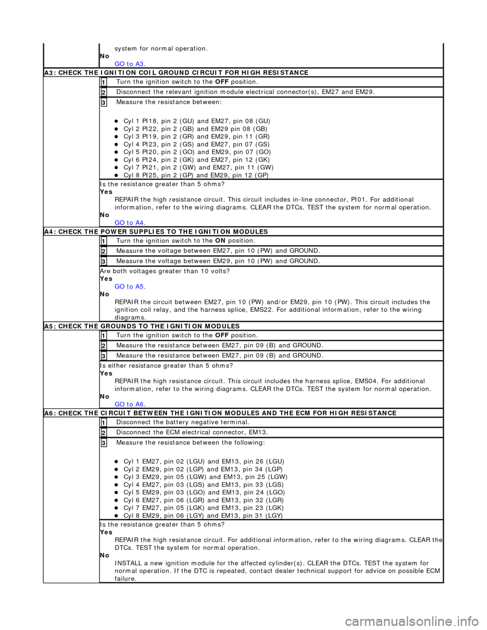
A3
: CHECK THE IGNITION COIL GROUND CIRCUIT FOR HIGH RESISTANCE
Turn the ignition swi
tch to the OFF
position.
1
Disc
onnect the relevant ignition module
electrical connector(s), EM27 and EM29.
2
Meas
ure the resistance between:
Cy
l 1 PI18, pin 2 (GU) and EM27, pin 08 (GU)
Cy
l 2 PI22, pin 2 (GB) and EM29 pin 08 (GB)
Cy
l 3 PI19, pin 2 (GR) and EM29, pin 11 (GR)
Cy
l 4 PI23, pin 2 (GS)
and EM27, pin 07 (GS)
Cy
l 5 PI20, pin 2 (GO) and EM29, pin 07 (GO)
Cy
l 6 PI24, pin 2 (GK) and EM27, pin 12 (GK)
Cy
l 7 PI21, pin 2 (GW) and EM27, pin 11 (GW)
Cy
l 8 PI25, pin 2 (GP) an
d EM29, pin 12 (GP)
3
Is th
e resistance greater than 5 ohms?
Yes REPAIR the high resistance circui t. This circuit includes in-line connector, PI01. For additional
information, refer to the wiring diagrams. CLEAR the DTCs. TEST the system for normal operation.
No GO to A4
.
A4:
CHECK THE POWER SUPPLIES TO THE IGNITION MODULES
Turn the ignition swi
tch to the ON
position.
1
Meas
ure the voltage between EM27, pin 10 (PW) and GROUND.
2
Meas
ure the voltage between EM29, pin 10 (PW) and GROUND.
3
Are both
voltages greater than 10 volts?
Yes GO to A5
.
No
REPAIR the circuit between EM27, pin 10 (PW) and/or EM29, pin 10 (PW). This circuit includes the
ignition coil relay, and the harness splice, EMS22. For additional information, refer to the wiring
diagrams.
A5:
CHECK THE GROUNDS TO THE IGNITION MODULES
Turn the ignition swi
tch to the OFF
position.
1
Meas
ure the resistance between EM27, pin 09 (B) and GROUND.
2
Meas
ure the resistance between EM27, pin 09 (B) and GROUND.
3
Is either resi
stance
greater than 5 ohms?
Yes REPAIR the high resistance circui t. This circuit includes the harness splice, EMS04. For additional
information, refer to the wiring diagrams. CLEAR the DTCs. TEST the system for normal operation.
No GO to A6
.
A6: CHECK
THE CIRCUIT BETWEEN THE IGNITION
MODULES AND THE ECM FOR HIGH RESISTANCE
Di
sconnect the battery negative terminal.
1
D
isconnect the ECM electrical connector, EM13.
2
Meas
ure the resistance between the following:
Cy
l 1 EM27, pin 02 (LGU) and EM13, pin 26 (LGU)
Cy
l 2 EM29, pin 02 (LGP) and EM13, pin 34 (LGP)
Cy
l 3 EM29, pin 05 (LGW) and EM13, pin 25 (LGW)
Cy
l 4 EM27, pin 03 (LGS) and EM13, pin 33 (LGS)
Cy
l 5 EM29, pin 03 (LGO) and EM13, pin 24 (LGO)
Cy
l 6 EM27, pin 06 (LGR) and EM13, pin 32 (LGR)
Cy
l 7 EM27, pin 05 (LGK) and EM13, pin 23 (LGK)
Cy
l 8 EM29, pin 06 (LGY) and EM13, pin 31 (LGY)
3
Is th
e resistance greater than 5 ohms?
Yes REPAIR the high resistance circuit. For additional information, refer to the wiring diagrams. CLEAR the
DTCs. TEST the system for normal operation.
No INSTALL a new ignition module for the affected cy linder(s). CLEAR the DTCs. TEST the system for
normal operation. If the DTC is re peated, contact dealer technical support for advice on possible ECM
failure.
Page 1096 of 2490
RE
PAIR the circuit between the EGR valve and battery. This circuit includes the EMS relay and the
EMS fuse box. For additional info rmation, refer to the wiring diagrams. CLEAR the DTC. TEST the
system for normal operation.
No GO to A2
.
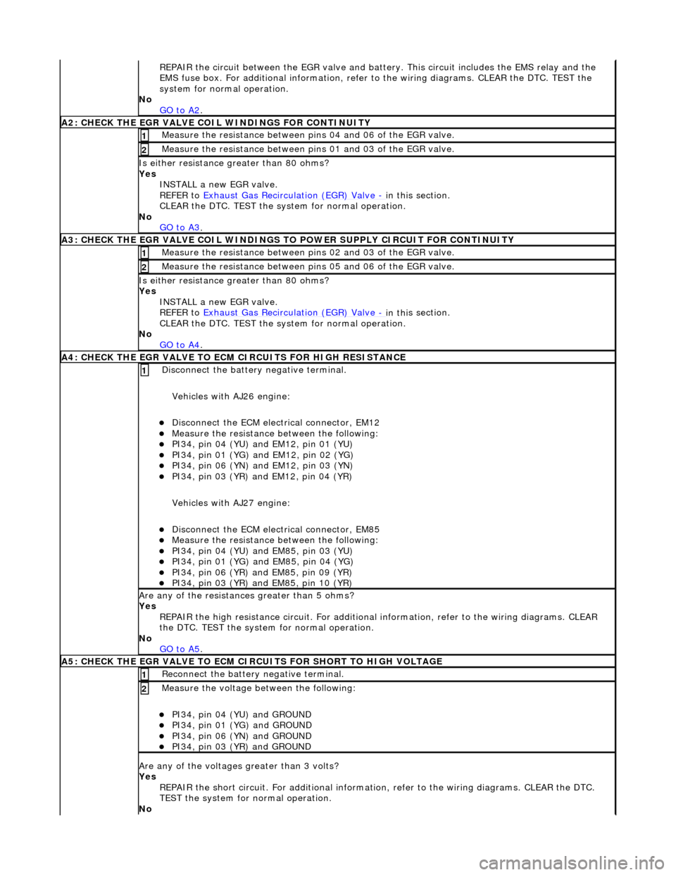
A2: CHECK THE EGR VALVE COIL WIND
INGS FOR CONTINUITY
Meas
ure t
he resistance between pins 04 and 06 of the EGR valve.
1
Meas
ure t
he resistance between pins 01 and 03 of the EGR valve.
2
Is either resi
stance
greater
than 80 ohms?
Yes INSTALL a new EGR valve.
REFER to Exhaust Gas Recirculation (EGR) Valve
- in thi
s section.
CLEAR the DTC. TEST the syst em for normal operation.
No GO to A3
.
A3: CHECK THE EGR VALVE COIL WINDINGS TO
POWER SUPPLY CIRCUIT FOR CONTINUITY
Meas
ure t
he resistance between pins 02 and 03 of the EGR valve.
1
Meas
ure t
he resistance between pins 05 and 06 of the EGR valve.
2
Is either resi
stance greater
than 80 ohms?
Yes INSTALL a new EGR valve.
REFER to Exhaust Gas Recirculation (EGR) Valve
- in thi
s section.
CLEAR the DTC. TEST the syst em for normal operation.
No GO to A4
.
A4: CHECK THE EGR VALVE T
O ECM
CIRCUITS FOR HIGH RESISTANCE
Disc
onnect the battery negative terminal.
Vehicles with AJ26 engine:
D i
sconnect the ECM electrical connector, EM12
Meas
ure t
he resistance between the following:
PI34, pin
0
4 (YU) and EM12, pin 01 (YU)
PI34,
pi
n 01 (YG) and EM12, pin 02 (YG)
PI34, pin
0
6 (YN) and EM12, pin 03 (YN)
PI34,
pi
n 03 (YR) and EM12, pin 04 (YR)
Vehicles with AJ27 engine:
D i
sconnect the ECM electrical connector, EM85
Meas
ure t
he resistance between the following:
PI34, pin
0
4 (YU) and EM85, pin 03 (YU)
PI34, pi
n 01 (YG) and EM85, pin 04 (YG)
PI34, pi
n 06 (YR) and EM85, pin 09 (YR)
PI34, pi
n 03 (YR) and EM85, pin 10 (YR)
1
Are an
y of the resistances greater than 5 ohms?
Yes REPAIR the high resistance circui t. For additional information, refer to the wiring diagrams. CLEAR
the DTC. TEST the system for normal operation.
No GO to A5
.
A5: CHECK THE EGR VALVE T
O ECM CIRCUITS FOR SHORT TO HIGH VOLTAGE
R
e
connect the battery negative terminal.
1
Meas
ure t
he voltage between the following:
PI34, pin
0
4 (YU) and GROUND
PI34, pin
0
1 (YG) and GROUND
PI34, pin
0
6 (YN) and GROUND
PI34, pin
0
3 (YR) and GROUND
2
Are any of th
e volt
ages greater than 3 volts?
Yes REPAIR the short circuit. For addi tional information, refer to the wiring diagrams. CLEAR the DTC.
TEST the system for normal operation.
No
Page 1097 of 2490

GO to A6.
A6: CHECK
THE EGR VALVE TO ECM
CIRCUITS FOR SHORT TO GROUND
Meas
ure the resistance between the following:
PI34, pin
04 (YU) and GROUND
PI34, pin
01 (YG) and GROUND
PI34, pin
06 (YN) and GROUND
PI34, pin
03 (YR) and GROUND
1
Are
any of the resistances less than 10,000 ohms?
Yes REPAIR the short circuit. For addi tional information, refer to the wiring diagrams. CLEAR the DTC.
TEST the system for normal operation.
No Contact dealer technical support for advice on possible ECM failure.
Page 1160 of 2490
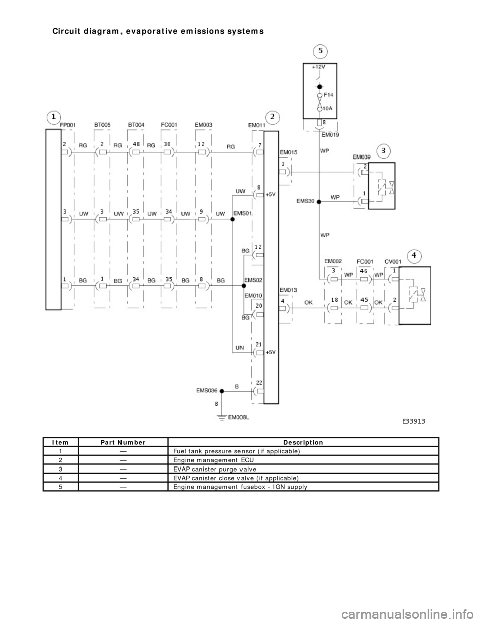
Ite
m
Part
Number
Descr
iption
1—Fu
el tank pressure sensor (if applicable)
2—Engine m
anagement ECU
3—EVAP canister purge va
lve
4—EVAP ca
nister close valve (if applicable)
5—Engine
mana
gement fusebox - IGN supply
Circuit diagram
,
evaporative emissions systems
Page 1163 of 2490
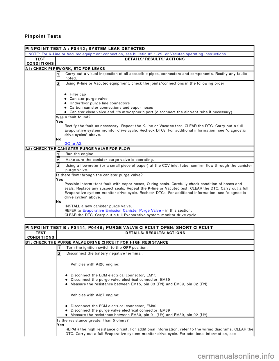
Pinpoint Tests
P
INPOINT TEST A : P0442; SYSTEM LEAK DETECTED
•
NOTE: For K-Line or Vacutec equipment connection, see bulletin 05.1-29, or Vacutec operating instructions
TE
ST
CONDITIONS
D
ETAILS/RESULTS/ACTIONS
A
1: CHECK PIPEWORK, ETC FOR LEAKS
Carr
y out a visual inspection of all accessible pipes, connectors and components. Rectify any faults
noted.
1
U
sing K-line or Vacutec equipment, check the
joints/connections in the following order:
Fi
ller cap
Cani
ster purge valve
Underfl
oor purge line connectors
Carbon
canister connections and vapor hoses
Cani
ster close valve and it's atmospheric port (disconnect the air vent tube if necessary)
2
Was
a fault found?
Yes Rectify the fault as necessary. Re peat the K-line or Vacutec test. CLEAR the DTC. Carry out a full
Evaporative system monitor drive cycle. Recheck DT Cs. For additional information, see "diagnostic
drive cycles" above.
No GO to A2
.
A2: CHECK
THE CA
NISTER PURGE VALVE FOR FLOW
Ru
n the engine.
1
Make sure the canister purge
valve is operating.
2
Using a flowmeter
(or a small piece
of paper) at the CCV inlet tube, confirm flow through the canister
purge valve.
3
Is th
ere flow through the canister purge valve?
Yes Possible intermittent faul t with vapor hoses, O-ring seals. Carefully check condition of hoses and
seals. Replace any suspect seals. Repeat the K-line or Vacutec test. CLEAR the DTC. Carry out a full
Evaporative system monitor drive cycle. Recheck DT Cs. For additional information, see "diagnostic
drive cycles" above.
No INSTALL a new canister purge valve.
REFER to Evaporative Emission Canister Purge Valve
- in t
his section.
CLEAR the DTC. Carry out a full Evap orative system monitor drive cycle.
P
INPOINT TEST B : P0444, P0445; PURGE VALVE CIRCUIT OPEN/SHORT CIRCUIT
TE
ST
CONDITIONS
D
ETAILS/RESULTS/ACTIONS
B1: CHECK
THE PURGE VALVE DRIV
E CIRCUIT FOR HIGH RESISTANCE
Turn the ignition swi
tch to the OFF
position.
1
Di
sconnect the battery negative terminal.
Vehicles with AJ26 engine:
Disc
onnect the ECM electrical connector, EM15
Di
sconnect the purge valve electrical connector, EM39
Meas
ure the resistance between EM15,
pin 03 (PN) and EM39, pin 02 (PN)
Vehicles with AJ27 engine:
Disc
onnect the ECM electrical connector, EM80
Di
sconnect the purge valve electrical connector, EM39
Meas
ure the resistance between EM80, pin 01 (UY) and EM39, pin 02 (UY)
2
Is th
e resistance greater than 5 ohms?
Yes REPAIR the high resistance circuit. For additional information, refer to the wiring diagrams. CLEAR the
DTC. Carry out a full Evaporative system monitor drive cycle. For additional information, see
Page 1164 of 2490
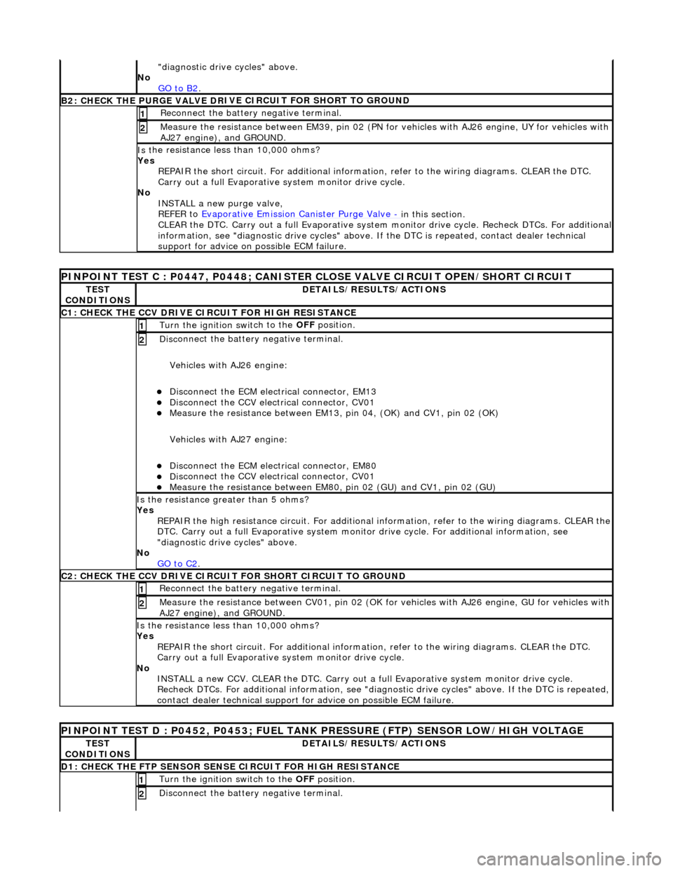
"d
iagnostic drive cycles" above.
No GO to B2
.
B2: CHECK THE PURGE VALVE DR
IV
E CIRCUIT FOR SHORT TO GROUND
Re
connect the battery negative terminal.
1
Meas
ure t
he resistance between EM39, pin 02 (PN for vehicles with AJ26
engine, UY for vehicles with
AJ27 engine), and GROUND.
2
Is t
he resistance less than 10,000 ohms?
Yes REPAIR the short circuit. For addi tional information, refer to the wiring diagrams. CLEAR the DTC.
Carry out a full Evaporative system monitor drive cycle.
No INSTALL a new purge valve,
REFER to Evaporative Emission Canister Purge Valve
- in thi
s section.
CLEAR the DTC. Carry out a full Evaporative system monitor drive cycle. Recheck DTCs. For additional
information, see "diagnostic drive cycles" above. If the DTC is repeated, contact dealer technical
support for advice on possible ECM failure.
PI
NPOINT TEST C : P0447, P0448; CANISTER CLOSE VALVE CIRCUIT OPEN/SHORT CIRCUIT
TE
S
T
CONDITIONS
D E
TAILS/RESULTS/ACTIONS
C1
: CH
ECK THE CCV DRIVE CIRCUIT FOR HIGH RESISTANCE
Turn the ignition swi
t
ch to the
OFF position.
1
Disc
onnect the battery negative terminal.
Vehicles with AJ26 engine:
Disc onne
ct the ECM electrical connector, EM13
Di
sc
onnect the CCV electrical connector, CV01
Meas
ure t
he resistance between EM13, pi
n 04, (OK) and CV1, pin 02 (OK)
Vehicles with AJ27 engine:
Disc onne
ct the ECM electrical connector, EM80
Di
sc
onnect the CCV electrical connector, CV01
Meas
ure t
he resistance between EM80,
pin 02 (GU) and CV1, pin 02 (GU)
2
Is the res
istance greater than 5 ohms?
Yes REPAIR the high resistance circuit. For additional information, refer to the wiring diagrams. CLEAR the
DTC. Carry out a full Evaporative system monitor drive cycle. For additional information, see
"diagnostic drive cycles" above.
No GO to C2
.
C2: CH
ECK THE CCV DRIVE CIRCUI
T FOR SHORT CIRCUIT TO GROUND
Re
connect the battery negative terminal.
1
Meas
ure t
he resistance between CV01,
pin 02 (OK for vehicles with AJ26 engine, GU for vehicles with
AJ27 engine), and GROUND.
2
Is t
he resistance less than 10,000 ohms?
Yes REPAIR the short circuit. For addi tional information, refer to the wiring diagrams. CLEAR the DTC.
Carry out a full Evaporative system monitor drive cycle.
No INSTALL a new CCV. CLEAR the DTC. Carry out a fu ll Evaporative system monitor drive cycle.
Recheck DTCs. For additional inform ation, see "diagnostic drive cycles" above. If the DTC is repeated,
contact dealer technical support for advice on possible ECM failure.
P INPOINT TES
T D : P0452, P0453; FUEL TANK
PRESSURE (FTP) SENSOR LOW/HIGH VOLTAGE
TES
T
CONDITIONS
DE
TAILS/RESULTS/ACTIONS
D
1:
CHECK THE FTP SENSOR SENSE CIRCUIT FOR HIGH RESISTANCE
Turn the ignition swi
t
ch to the OFF
position.
1
Disc
onnect the battery negative terminal.
2
Page 1165 of 2490

Vehicles with AJ26 en
gine:
D
isconnect the ECM electrical connector, EM11
Di
sconnect the FTP sensor electrical connector, FP01
Meas
ure the resistance between EM11,
pin 07 (RG) and FP01, pin 02 (RG)
Vehicles with AJ27 engine:
D
isconnect the ECM electrical connector, EM81
Di
sconnect the FTP sensor electrical connector, FP01
Meas
ure the resistance between EM81,
pin 16 (RG) and FP01, pin 02 (RG)
Is th
e resistance greater than 5 ohms?
Yes REPAIR the high resistance circuit. For additional information, refer to the wiring diagrams. CLEAR the
DTC. Carry out a full Evaporative system monitor drive cycle. For additional information, see
"diagnostic drive cycles" above.
No GO to D2
.
D2: CHECK
THE FTP SENSOR SENSE CI
RCUIT FOR SHORT CIRCUIT TO GROUND
R
econnect the battery negative terminal.
1
Meas
ure the resistance between
FP01, pin 07 (RG) and GROUND.
2
Is
the resistance less than 10,000 ohms?
Yes REPAIR the short circuit. For addi tional information, refer to the wiring diagrams. CLEAR the DTC.
Carry out a full Evaporative system monitor drive cycle.
No GO to D4
.
D3: CHECK
THE FTP SENSOR SENSE CIRCUI
T FOR SHORT CIRCUIT TO HIGH VOLTAGE
Turn the ignition swi
tch to the ON
position.
1
Measure the
voltage between FP
01, pin 02 (RG) and GROUND.
2
Is th
e voltage greater than 3 volts?
Yes REPAIR the short circuit. For addi tional information, refer to the wiring diagrams. CLEAR the DTC.
Carry out a full Evaporative system monitor drive cycle.
No GO to D4
.
D
4: CHECK THE FTP SENSOR SIGNAL GROUND CIRCUIT FOR HIGH RESISTANCE
Di
sconnect the battery negative terminal.
Vehicles with AJ26 engine:
D
isconnect the ECM electrical connector, EM10
Meas
ure the resistance between EM11, pin 12 (BG) and FP01, pin 01 (BG)
Meas
ure the resistance between EM10, pin 20 (BG) and FP01, pin 01 (BG)
Vehicles with AJ27 engine:
Re
connect the ECM electrical connector, EM81
D
isconnect the ECM electrical connector, EM82
D
isconnect the ECM electrical connector, EM83
Meas
ure the resistance between EM82, pin 07 (BG) and FP01, pin 01 (BG)
Meas
ure the resistance between EM83, pin 13 (BG) and FP01, pin 01 (BG)
1
Is either resi
stance
greater than 5 ohms?
Yes REPAIR the high resistance circui t. This circuit includes harness splice, EMS02. For additional
information, refer to the wiring diagrams. CLEAR the DTC. Carry out a full Evaporative system
monitor drive cycle. For additional informat ion, see "diagnostic drive cycles" above.
No GO to D5
.
D5:
CHECK THE FTP SENSOR SIGNAL GROUND
CIRCUIT FOR SHORT CIRCUIT TO GROUND
R
econnect the battery negative terminal.
1
Meas
ure the resistance between
FP01, pin 01 (BG) and GROUND.
2
Is
the resistance less than 10,000 ohms?
Page 1166 of 2490

Yes
R
EPAIR the short circuit. For addi
tional information, refer to the wiring diagrams. CLEAR the DTC.
Carry out a full Evaporative system monitor drive cycle.
No GO to D6
.
D6: CHECK
THE FTP SENSOR POWER SU
PPLY CIRCUIT FOR HIGH RESISTANCE
Disc
onnect the battery negative terminal.
Vehicles with AJ26 engine:
Measure t
he resistance between EM11,
pin 08 (UW) and FP01, pin 03 (UW)
Measure t
he resistance between EM10,
pin 21 (UW) and FP01, pin 03 (UW)
Vehicles with AJ27 engine:
Meas ure t
he resistance between EM82,
pin 01 (OY) and FP01, pin 03 (OY)
Measure t
he resistance between EM83,
pin 05 (OY) and FP01, pin 03 (OY)
1
Is either resistance greater
than 5 ohms?
Yes
REPAIR the high resistance circui t. This circuit includes harness splice, EMS01. For additional
information, refer to the wiring diagrams. CLEAR the DTC. Carry out a full Evaporative system
monitor drive cycle. For additional informat ion, see "diagnostic drive cycles" above.
No GO to D7
.
D7: CHECK
THE FTP SENSOR WIRING
FOR SHORT CIRCUIT TO EACH OTHER
Measure
the resistance between FP01, pins 01 (BG) and 02 (RG).
1
M
e
asure the resistance between FP01, pins 02 (RG) and 03 (UW).
2
Is either resi
stance le
ss than 10,000 ohms?
Yes REPAIR the short circuit. For addi tional information, refer to the wiring diagrams. CLEAR the DTC.
Carry out a full Evaporative system monitor drive cycle.
No INSTALL a new FTP sensor. CLEAR the DTC. Carry out a full Evaporative system monitor drive cycle.
For additional information, see "diagnostic drive cycles" above.
Page 1182 of 2490
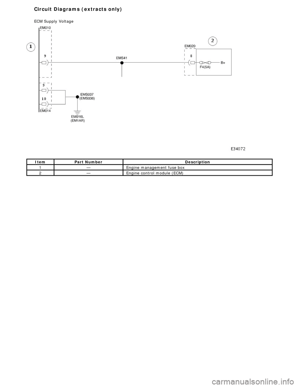
Ite
m
Par
t
Number
De
scr
iption
1—Engine
management fuse box
2—Engine
control module (E
CM)
Circuit Diagrams (extracts only)
ECM Su
pply Voltage