diagram JAGUAR X308 1998 2.G Workshop Manual
[x] Cancel search | Manufacturer: JAGUAR, Model Year: 1998, Model line: X308, Model: JAGUAR X308 1998 2.GPages: 2490, PDF Size: 69.81 MB
Page 40 of 2490
irri
tation and dermatitis. In addition, used engine oil contains potentially harmful contaminants which may cause skin
cancer. Washing facilities and adequate means of skin protection should be provided.
Observe these recommendations:
Wear pro t
ective clothing and impe
rvious gloves when necessary.
Do not put oily
rags in pockets. Avoid contaminat
ing clothes, particularly underwear, with oil.
Overal
ls must be cleaned re
gularly; discard oil impregna ted clothing and footwear wh ich cannot be washed or
cleaned.
Fi rst
Aid treatment should be obtained
immediately for open cuts or wounds.
Use barrier
creams, applying before each work period, to en
able easier removal of dirty oil and grease from the skin.
Wa
sh with soap and water to ensure th
at all oil is removed (skin cleaner and a nail brush will help). The use of
preparations containing lanolin will help to replace the natural skin oils which have been removed.
Do
not use petrol, kerosene, gas oil, th
inners or solvents for washing skin.
If
skin disorders develop, obtain medical advice immediately.
Wh
ere prac
ticable, degrease components prior to handling.
W
h
ere there is a risk of fluids coming into contact with th
e eyes, suitable eye protection should be worn - goggles or
face shield. An eye wash facility should be provided.
Ensure that a
dequate ventilation is provided when volatile degreasing agents are being used.
E
n
vironmental Protection
In so
m
e countries it is illegal to pour used oil onto the ground
, down sewers or drains, or into water courses. The burning of
used engine oil in small space heaters or boilers is not reco mmended unless emission control equipment is fitted. Dispose of
used oil through authorized waste disposal contractors, to licensed waste disposal sites or to the waste oil reclamation
trade. If in doubt, contact the Local Authority for advice on disposal facilities.
On-Board Diagnostics (OBD)
Ve
hicles use programmed electronic control systems to prov
ide engine management and emission regulation, automatic
transmission operation and anti -lock braking control. These control systems ha ve an integral On-Board Diagnostics (OBD)
facility for use in conjunction with either Jaguar diagnostic equipment or a scan t ool which is capable of retrieving DTCs,
PIDs and performing active commands.
The OBD information in this manual provid es diagnostic and rectification procedures for emission related electrical and
mechanical systems. The informat ion is intended to facilitate fault diagnosis and the subsequent rectification of vehicles
without recourse to the portab le diagnostic unit (PDU).
OBD related information can be fo und in the following sections:
General Information
Engine M
anagement System
Auto
matic Transmission
Anti-lock Br
aking System
Where appropriate a section comprises the following sub-sections:
Description and Operation
A ge
neral illustration and parts list to help the identi
fication of the particular system or component.
A b
rief description of the system operating characteristics and monitoring procedure
accompanied by a component
illustration.
Addi ti
onal information, where appropriat
e, is provided in the form of component calibrations, characteristics and
cross sectional views.
A localized circui
t diagram is included to provide circuit iden
tification and details of connectors, splices, fuses, wire
gauge and colors. See Circuit Diagrams.
Diagnosis and Testing (dedicated to fault analysis and rectification)
Recommended special tools. Symptom chart; a ch
art contai
ning all relevant Diagnostic Trouble Code s (DTC), their possible causes and an
indication of the appropriate test.
Sp
ecific pinpoint test(s), de
signed so that fault diagnosis can be carr ied out in a logical and efficient manner.
Page 41 of 2490
•
NOTE: For convenience, pinpoint test il
lustrations indicating voltage measurements do not always accurately reflect the
conventional method of connecting a multimeter. More explicitly, if the multimeter probes are connected as shown in some
illustrations (positive probe to ground), the voltage reading would be preceded by the negative sign '-', indicating that the
probes have been connected in the reverse manner to the norm al convention. The accuracy of the reading is not affected
and the '-' sign can be ignored when comparing the reading with the results indicated in the text of the pinpoint test.
Removal and Installation
Re
moval procedure(s), formatted
in the recommended sequence
Il
lustrated guide to the use of special tools
Il
lustrations to support the relevant text
Installation
procedure as above and including special re
commendations for processes, lubricants and tightening
torques.
Cir
cuit Diagrams
To
understand the relationship between the vehicle electric
al system and the system circuit diagrams, refer to the
appropriate Electrical Guide.
Fault Identificatio
n (DTC)
The diagnostic trouble codes (DTCs) are
li
sted in Section 303-00 under Diagno
stic Trouble Codes and include, where
applicable, the corresponding manual section reference.
Page 278 of 2490
Vehicle Dynamic Suspension - Vehicle Dynamic Suspension
Diagn
osis and Testing
Refer to the PDU User Guide for details of diagnosing and testing the Adaptive Damping System. The PDU interrogates the
ADCM directly via the K and L lines to the J1962 diagnostic socket.
The PDU will give an indication of the integrity of each electron ic and electrical component. It will indicate, for example, that
the accelerometers are not broken, but not that they functionin g correctly when the vehicle is in motion. However, it is
exceptional for an accelero meter to function incorrectly in its dynamic mode if it is proved to be functioning when static.
Basic Checks
The accele
rometers have the following ch
aracteristics. At 0g (no movement of the body) each vertical accelerometer
outputs approximately 2.5V steady voltage; the lateral acce lerometer outputs approximately 1.5V. The voltage output due
to body movement is proportional to acceleration in the acceleration axis, up to approximately 4.5V and down to
approximately 0.5V.
Before changing any component, refer to the circuit diagrams and check the cont inuity of relevant harness circuits; in some
instances, the PDU will not different iate between a faulty component an d a damaged connection or wiring.
Check the following fuses:
En
gine compartment fuse
box, fuse F5 (10A).
Engine m
anagement fuse
box, fuse F1 (20A).
Check the following ADCM input/output lines:
Sy stem erro
r output from the ADCM
to the instrument cluster.
Vehicl
e speed output from the inst
rument cluster to the ADCM.
Foo
tbrake signal to the ADCM.
Check any relevant connections to confirm that the connection is electrically sound and that a terminal pin has not been
pushed back into the connector shell, ie. not ma king a connection to its mating pin or socket.
Page 433 of 2490
clos
ed outlet valves.
Traction Control
Trac
tion control has the same capabilities as ASC but with th
e added ability to actuate the brakes of the spinning wheel.
This enhances ASC by improving acceleration particularly on surfaces with uneven friction , e.g. one wheel on ice the other
on tarmac.
When wheelspin occurs, brake line pressure to the slipping wheel is generated, to operate that wheel's brake. The BCM
achieves this by closing the cut-off solenoid valve and oper ating the hydraulic pump. Brake fluid is then drawn from the
reservoir through the non-actuated mast er cylinder to the brake caliper.
A 'TRAC' amber warning light flashes on the instrument panel when the system detects a spinning wheel.
The traction control system uses a brake control modulator with nine solenoid valv es: four normally open inlet valves and
four normally closed outlet valves and one special isolating va lve. The outlet valves control the brakes of each each rear
wheel individually on the traction control system.
Rear Wheel Speed Senso
rs and ABS/TCCM Circuit Diagram
Page 461 of 2490
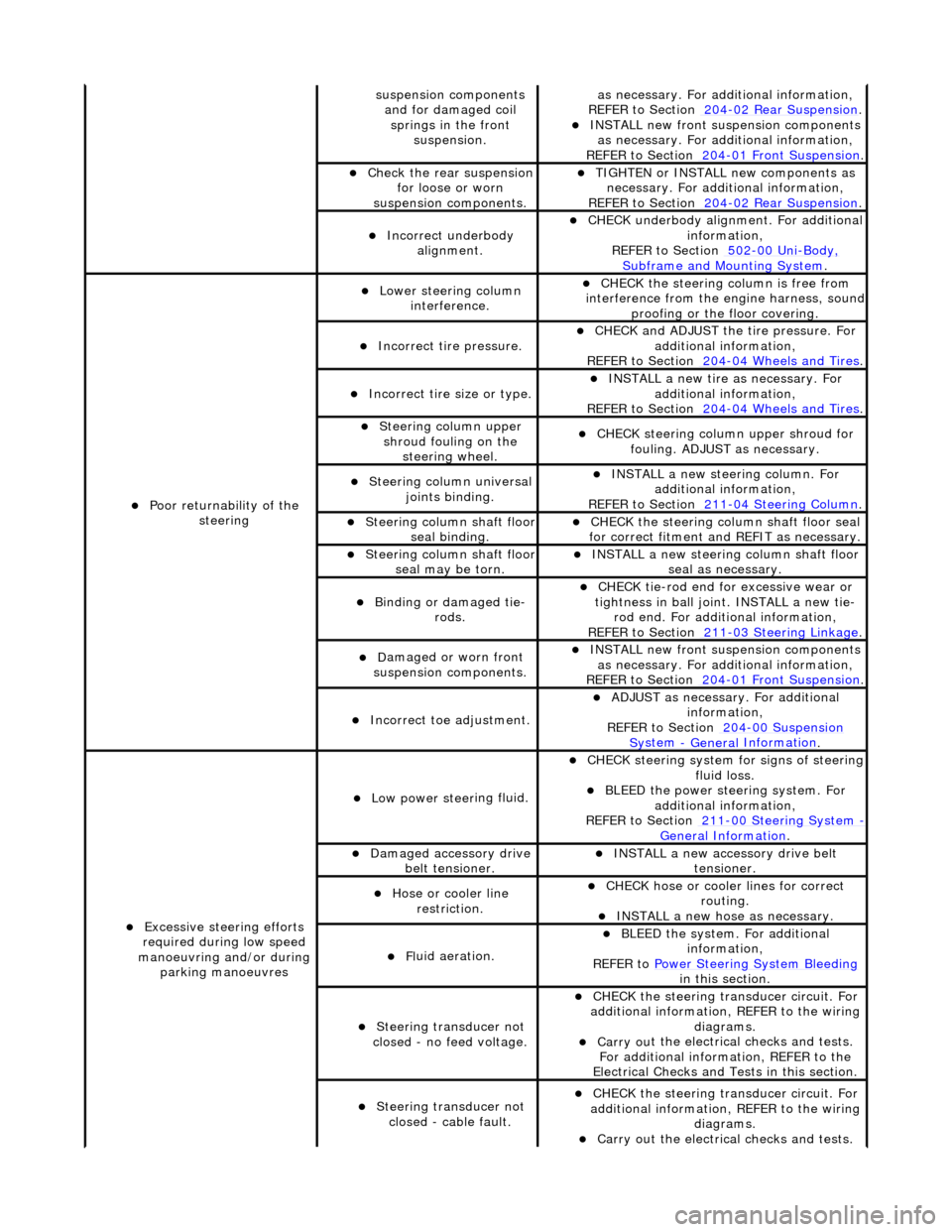
sus
pension components
and for damaged coil springs in the front suspension.
as necessary. For addi tional information,
REF
ER to Section 204
-0
2 Rear Suspension
. I
NSTALL new front suspension components
as necessary. For addi tional information,
REFER to Section 204
-01
Front Suspension
.
Chec
k the rear suspension
for loose or worn
suspension components.
TIGHTE
N or INSTALL new components as
necessary. For additi onal information,
REFER to Section 204
-0
2 Rear Suspension
.
Incorre
ct underbody
alignment.
CHECK
underbody alignment. For additional
information,
REFER to Section 502
-00
Uni
-Body, Subframe and M
ounting System
.
Poor r
eturnability of the
steering
Lower steeri
ng column
interference.
CHECK
the steering co
lumn is free from
interference from the en gine harness, sound
proofing or the floor covering.
Incorrect
tire pressure.
CHECK
and ADJUST the tire pressure. For
additional information,
REFER to Section 204
-0
4 Wheels and Tires
.
Incorrect
tire size or type.
IN
STALL a new tire as necessary. For
additional information,
REFER to Section 204
-0
4 Wheels and Tires
.
Steeri
ng column upper
shroud fouling on the steering wheel.
CHECK
steering column upper shroud for
fouling. ADJUST as necessary.
Steeri
ng column universal
joints binding.
IN
STALL a new steering column. For
additional information,
REFER to Section 211
-0
4 Steering Column
.
Steeri
ng column shaft floor
seal binding.
CHE
CK the steering column shaft floor seal
for correct fitm ent and REFIT as necessary.
Steeri
ng column shaft floor
seal may be torn.
IN
STALL a new steering column shaft floor
seal as necessary.
Bin
ding or damaged tie-
rods.
CHECK
tie-rod end for excessive wear or
tightness in ball joint. INSTALL a new tie- rod end. For additional information,
REFER to Section 211
-0
3 Steering Linkage
.
D
amaged or worn front
suspension components.
I
NSTALL new front suspension components
as necessary. For addi tional information,
REFER to Section 204
-01
Front Suspension
.
Incorre
ct toe adjustment.
AD
JUST as necessary. For additional
information,
REFER to Section 204
-00
Suspension
Sy
stem
- General
Information
.
Excessive steeri
ng efforts
required during low speed
manoeuvring and/or during parking manoeuvres
Low power steer
ing fluid.
CHE
CK steering system
for signs of steering
fluid loss.
BLEE
D the power steering system. For
additional information,
REFER to Section 211
-0
0 Steering System
- General Informati
on
.
Damaged accessory driv
e
belt tensioner.
INST
ALL a new accessory drive belt
tensioner.
Hose or cooler li
ne
restriction.
CHECK
hose or cooler lines for correct
routing.
INST
ALL a new hose as necessary.
Fl
uid aeration.
BLEE
D the system. For additional
information,
REFER to Power Steering System Bleeding
in t
his section.
Steeri
ng transducer not
closed - no feed voltage.
CHECK
the steering transducer circuit. For
additional information, REFER to the wiring diagrams.
Carry ou
t the electrical checks and tests.
For additional information, REFER to the
Electrical Checks and Tests in this section.
Steeri
ng transducer not
closed - cable fault.
CHECK
the steering transducer circuit. For
additional information, REFER to the wiring diagrams.
Carry ou
t the electrical checks and tests.
Page 462 of 2490
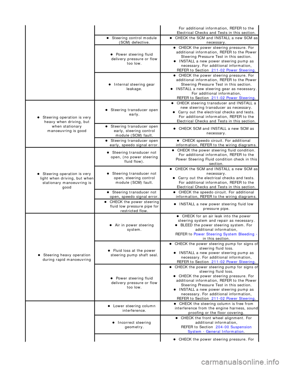
Fo
r additional information, REFER to the
Electrical Checks and Tests in this section.
Steering control
module
(SCM) defective.
CHECK
the SCM and INSTALL a new SCM as
necessary.
Power steeri ng f
luid
delivery pressure or flow too low.
CHECK
the power stee
ring pressure. For
additional information, REFER to the Power Steering Pressure Test in this section.
INSTALL a ne
w power steering pump as
necessary. For additi onal information,
REFER to Section 211
-0 2
Power Steering
.
Internal steering gear
leakage.
CHECK
the power stee
ring pressure. For
additional information, REFER to the Power Steering Pressure Test in this section.
INSTALL a ne
w steering
gear as necessary.
For additional information,
REFER to Section 211
-0 2
Power Steering
.
Steeri
ng operati
on is very
heavy when driving, but when stationary
manoeuvring is good
Steering transducer open earl
y.
CHECK
steering transducer and INSTALL a
new steering transducer as necessary.
Carry out th
e electrical checks and tests.
For additional information, REFER to the
Electrical Checks and Tests in this section.
Steering transducer open
early,
steering control
module (SCM) fault.
CHECK
SCM and INSTALL a new SCM as
necessary.
Steering transducer open
earl
y, speedo signal error.
CHECK
speedo
circui
t. For additional
information, REFER to the wiring diagrams.
Steeri ng operati
on is very
light when driving, but when
stationary manoeuvring is good
Steering transducer not
o
pen, (no power steering
fluid flow).
CHECK
the power steering fluid condition.
For additional information, REFER to the
Power Steering Fluid condition check in this section.
Steering transducer not o
pen, steering control
module (SCM) fault.
CHECK
the SCM and INSTALL a new SCM as
necessary.
Carry out th
e electrical checks and tests.
For additional information, REFER to the
Electrical Checks and Tests in this section.
Steering transducer not
o
pen, speedo signal error.
CHECK
the speedo circ
uit. For additional
information, REFER to the wiring diagrams.
CHECK
the power steering
fluid low pressure pipe for restricted flow.
INSTALL a ne
w power steering fluid low
pressure pipe.
S t
eering heavy operation
during rapid manoeuvring
Ai r i
n power steering
system.
CHECK for an air l
eak into the power
steering system and re pair as necessary.
BLEED the
power steering system. For
additional information,
REFER to Power Steering System Bleeding
- in t hi
s section.
Fluid loss at the power
steering pump shaft seal.
CHECK the power steer
ing pump for signs o
f steering fl
ui
d loss.
INST
ALL a ne
w power steering pump as
necessary. For additi onal information,
REFER to Section 211
-0 2
Power Steering
.
Power steeri
ng f
luid
delivery pressure or flow too low.
CHECK the power steer
ing pump for signs o
f steering fl
ui
d loss.
CHECK
the power stee
ring pressure. For
additional information, REFER to the Power Steering Pressure Test in this section.
INSTALL a ne
w power steering pump as
necessary. For additi onal information,
REFER to Section 211
-02
Power Steering
.
Lower steeri
ng col
umn
interference.
CHECK
the steering co
lumn is free from
interference from the en gine harness, sound
proofing or the floor covering.
Incorrect steering geometry. CHE
CK the front wheel alignment. For
additional information,
REFER to Section 204
-00 Sus
pension
Sy
ste
m
- General
Information
.
CHECK
the power stee
ring pressure. For
Page 463 of 2490
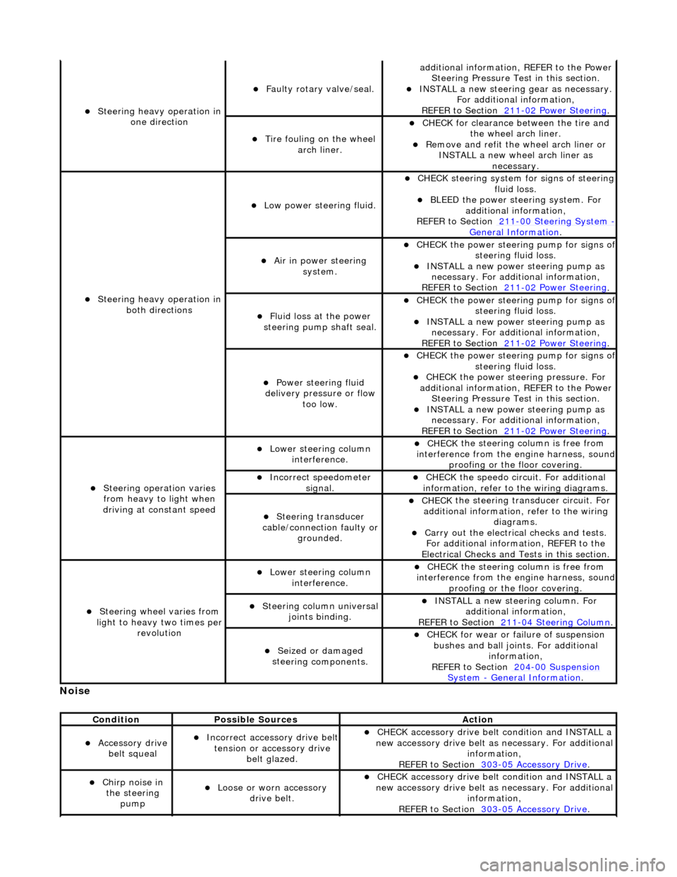
No
ise
S
teering heavy operation in
one direction
F
aulty rotary valve/seal.
addi
tional information, REFER to the Power
Steering Pressure Test in this section.
INST
ALL a new steering
gear as necessary.
For additional information,
REFER to Section 211
-0
2 Power Steering
.
Ti
re fouling on the wheel
arch liner.
CHECK for
clearance be
tween the tire and
the wheel arch liner.
R
emove and refit the wheel arch liner or
INSTALL a new wheel arch liner as necessary.
S
teering heavy operation in
both directions
Low power steer
ing fluid.
CHE
CK steering system
for signs of steering
fluid loss.
BLEE
D the power steering system. For
additional information,
REFER to Section 211
-0
0 Steering System
- General Informati
on
.
Ai
r in power steering
system.
CHECK
the power steering pump for signs o
f steering fl
uid loss.
INST
ALL a new power steering pump as
necessary. For additi onal information,
REFER to Section 211
-0
2 Power Steering
.
Fluid loss at the power
steering pump shaft seal.
CHECK
the power steering pump for signs o
f steering fl
uid loss.
INST
ALL a new power steering pump as
necessary. For additi onal information,
REFER to Section 211
-0
2 Power Steering
.
Power steeri
ng fluid
delivery pressure or flow too low.
CHECK
the power steering pump for signs o
f steering fl
uid loss.
CHECK
the power stee
ring pressure. For
additional information, REFER to the Power Steering Pressure Test in this section.
INST
ALL a new power steering pump as
necessary. For additi onal information,
REFER to Section 211
-0
2 Power Steering
.
Steeri
ng operation varies
from heavy to light when
driving at constant speed
Lower steeri
ng column
interference.
CHECK
the steering co
lumn is free from
interference from the en gine harness, sound
proofing or the floor covering.
Incorre
ct sp
eedometer
signal.
CHECK
the speedo circ
uit. For additional
information, refer to the wiring diagrams.
Steeri
ng transducer
cable/connection faulty or grounded.
CHECK
the steering transducer circuit. For
additional information, refer to the wiring diagrams.
Carry ou
t the electrical checks and tests.
For additional information, REFER to the
Electrical Checks and Tests in this section.
Steeri
ng wheel varies from
light to heavy two times per revolution
Lower steeri
ng column
interference.
CHECK
the steering co
lumn is free from
interference from the en gine harness, sound
proofing or the floor covering.
Steeri
ng column universal
joints binding.
IN
STALL a new steering column. For
additional information,
REFER to Section 211
-0
4 Steering Column
.
Seized or damaged
ste
ering components.
CHECK
for wear or failure of suspension
bushes and ball join ts. For additional
information,
REFER to Section 204
-00
Suspension
Sy
stem
- General
Information
.
Cond
ition
Possib
le Sources
Acti
on
Acce
ssory drive
belt squeal
Incorre
ct accessory drive belt
tension or accessory drive belt glazed.
CHECK
accessory drive belt condition and INSTALL a
new accessory drive belt as necessary. For additional
information,
REFER to Section 303
-0
5 Accessory Drive
.
Chir
p noise in
the steering pump
Loose or worn accessory dr
ive belt.
CHECK
accessory drive belt condition and INSTALL a
new accessory drive belt as necessary. For additional
information,
REFER to Section 303
-0
5 Accessory Drive
.
Page 932 of 2490
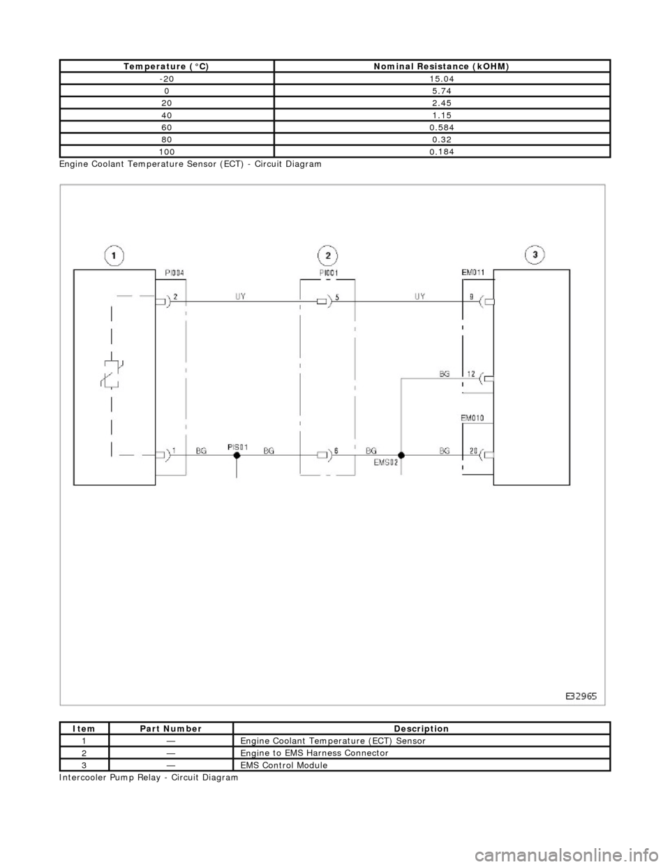
Engi
ne Coolant Temperature Sensor (ECT) - Circuit Diagram
Intercooler Pump Relay - Circuit Diagram
T emper
ature (°C)
No
mi
nal Resistance (kOHM)
-2
015 .0
4
05.7
4
202.45
401.15
600.
584
800.3
2
1000.
184
ItemPar
t
Number
De
scrip
tion
1—Eng
i
ne Coolant Temperature (ECT) Sensor
2—Eng
i
ne to EMS Harness Connector
3—EMS Con
trol Modu
le
Page 1016 of 2490
Pa
rts List
The pressure regulator is a diap hragm-operated valve that regula tes fuel-rail pressure at 3,0 bar above the intake manifold
pressure. A pipe connects the throttle induction elbow to the pressure regulator to provide the vacuum control signal. On
supercharged engines, the pressure regulator vacuum feed is taken from the top of the supercharger outlet duct.
The regulator is fitted between the rear end of the right-hand fuel rail (bank 1) and the fuel return line to the tank.
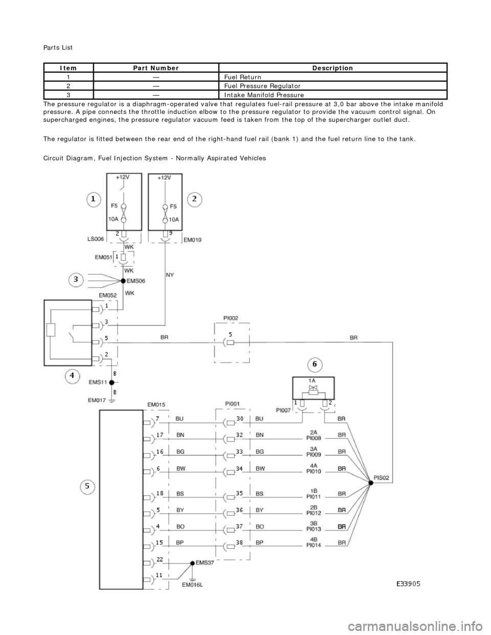
Circuit Diagram, Fuel Injection Syst em - Normally Aspirated Vehicles
Ite
m
Par
t
Number
De
scr
iption
1—F
u
el Return
2—F
u
el Pressure Regulator
3—Inta
k
e Manifold Pressure
Page 1017 of 2490
Ci
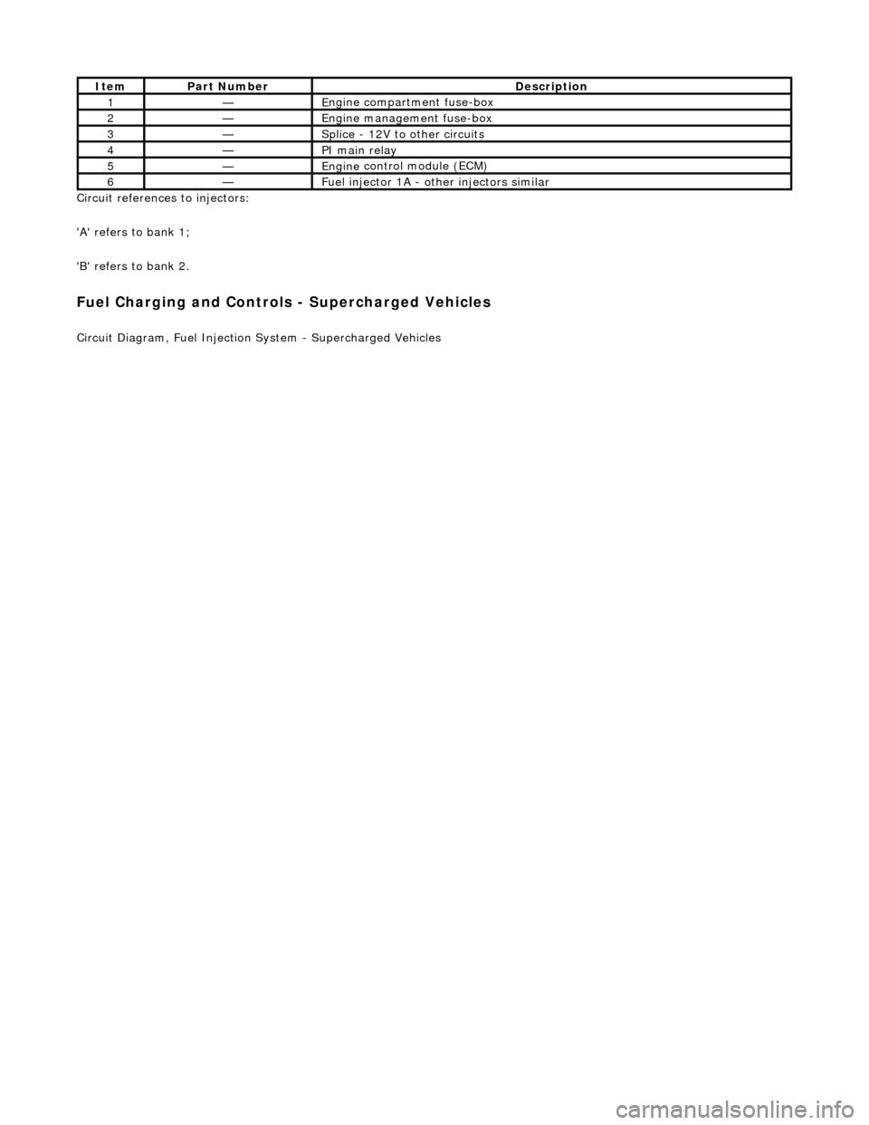
rcuit references to injectors:
'A' refers to bank 1;
'B' refers to bank 2.
Fuel C
harging and Controls - Supercharged Vehicles
Ci
rcuit Diagram, Fuel Injection
System - Supercharged Vehicles
It
em
Par
t Number
De
scription
1—E
ngine compartment fuse-box
2—Engine
management fuse-box
3—Splice
- 12V to
other circuits
4—PI m
ain relay
5—Engine
control module (ECM)
6—Fue
l injector 1A - other injectors similar