JAGUAR X308 1998 2.G User Guide
X308 1998 2.G
JAGUAR
JAGUAR
https://www.carmanualsonline.info/img/21/7640/w960_7640-0.png
JAGUAR X308 1998 2.G User Guide
Page 1544 of 2490
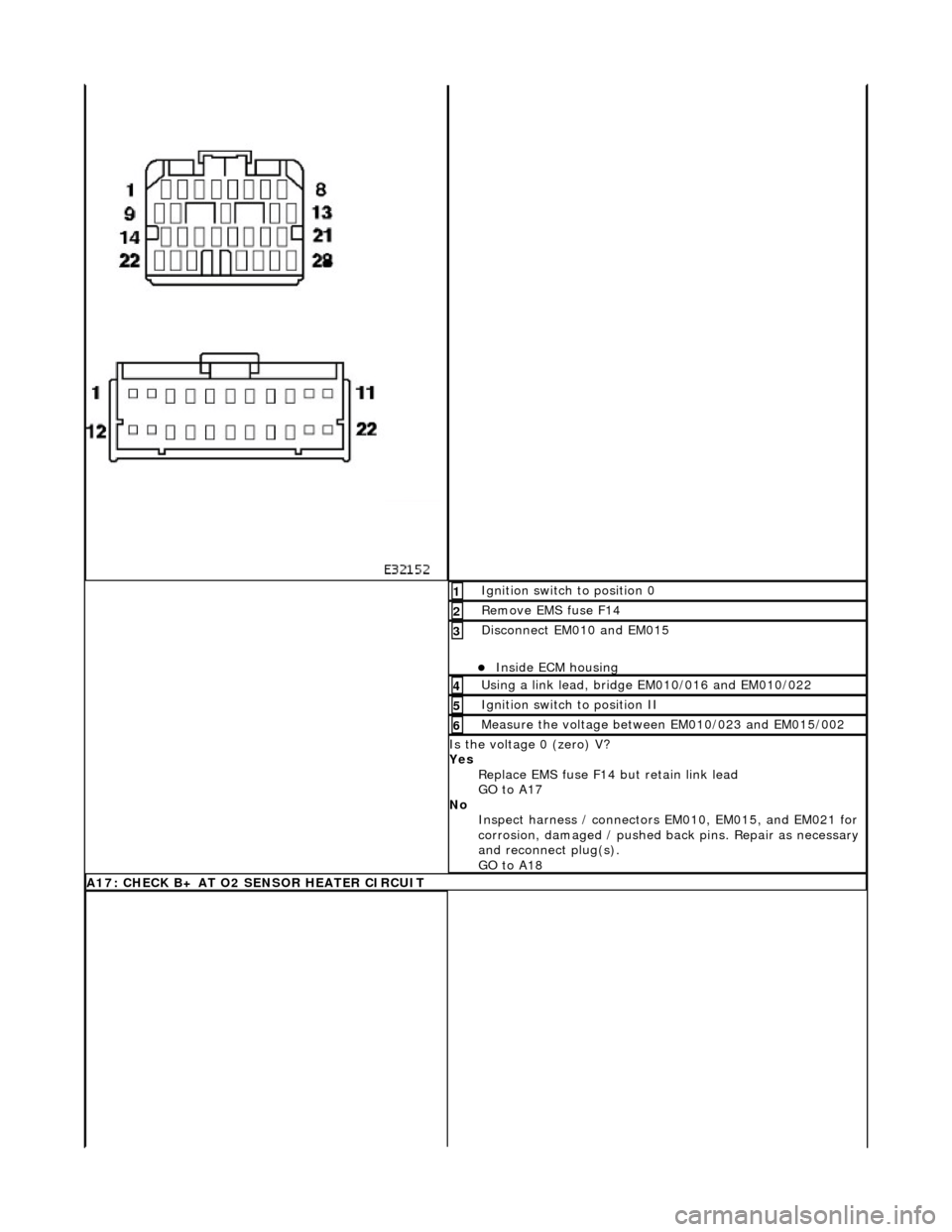
Ignition switch to position 0 1
Remove EMS fuse F14 2
Disconnect EM010 and EM015
Inside ECM housing
3
Using a link lead, bridge EM010/016 and EM010/022 4
Ignition switch to position II 5
Measure the voltage between EM010/023 and EM015/002 6
Is the voltage 0 (zero) V?
Yes Replace EMS fuse F14 but retain link lead
GO to A17
No Inspect harness / connectors EM010, EM015, and EM021 for
corrosion, damaged / pushed back pins. Repair as necessary
and reconnect plug(s).
GO to A18
A17: CHECK B+ AT O2 SENSOR HEATER CIRCUIT
Page 1553 of 2490
With EM012 and EM021 disconnected, measure the
resistance between EM012/022 and EM021/004. 1
Is the resistance < 0.5 OHM?
Yes GO to B15
No Inspect connectors EM012 and EM021 for corrosion,
damaged / pushed back pins.
Inspect harness / splice EM S08 for damage. Repair as
necessary and reconnect plug(s).
GO to B19
B15: CHECK FOR SHORT TO B+
Page 1554 of 2490
Ignition switch to position 0 1
Disconnect EM010
Inside ECM housing
2
Disconnect EM012
Inside ECM housing
3
Ignition switch to position II 4
Measure the voltage between EM010/023 and EM012/015. 5
Is the voltage 0 (zero) V?
Yes GO to B16
No Inspect harness / connectors EM010, EM012 and EM021 for
corrosion, damaged / pushed back pins. Repair as necessary
and reconnect plug(s).
GO to B19
B16: CHECK FOR SHORT TO B+
Measure the voltage between EM010/023 and EM012/022 1
Page 1556 of 2490
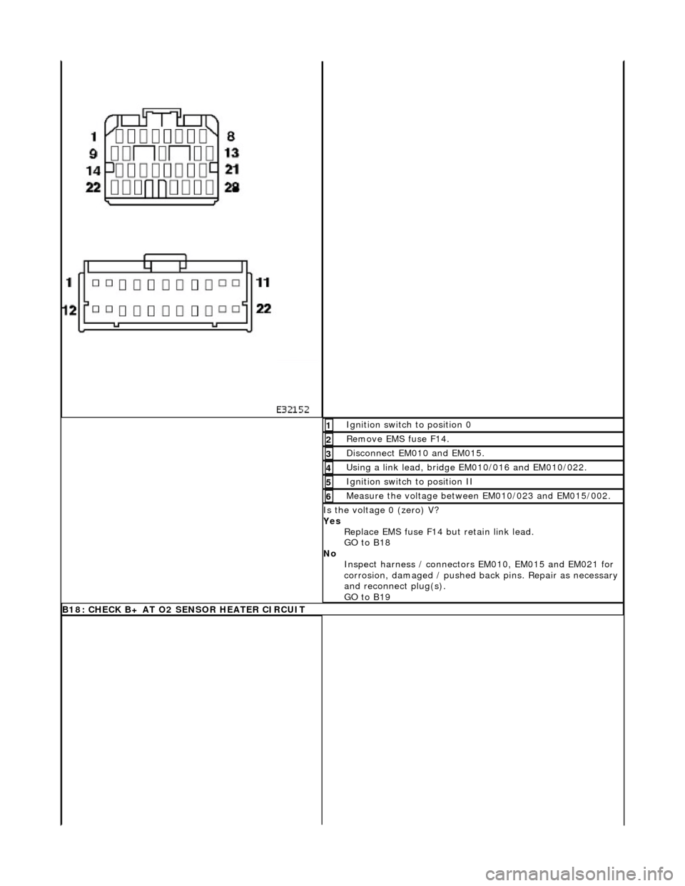
Ignition switch to position 0 1
Remove EMS fuse F14. 2
Disconnect EM010 and EM015. 3
Using a link lead, bridge EM010/016 and EM010/022. 4
Ignition switch to position II 5
Measure the voltage between EM010/023 and EM015/002. 6
Is the voltage 0 (zero) V?
Yes Replace EMS fuse F14 but retain link lead.
GO to B18
No Inspect harness / connectors EM010, EM015 and EM021 for
corrosion, damaged / pushed back pins. Repair as necessary
and reconnect plug(s).
GO to B19
B18: CHECK B+ AT O2 SENSOR HEATER CIRCUIT
Page 1558 of 2490
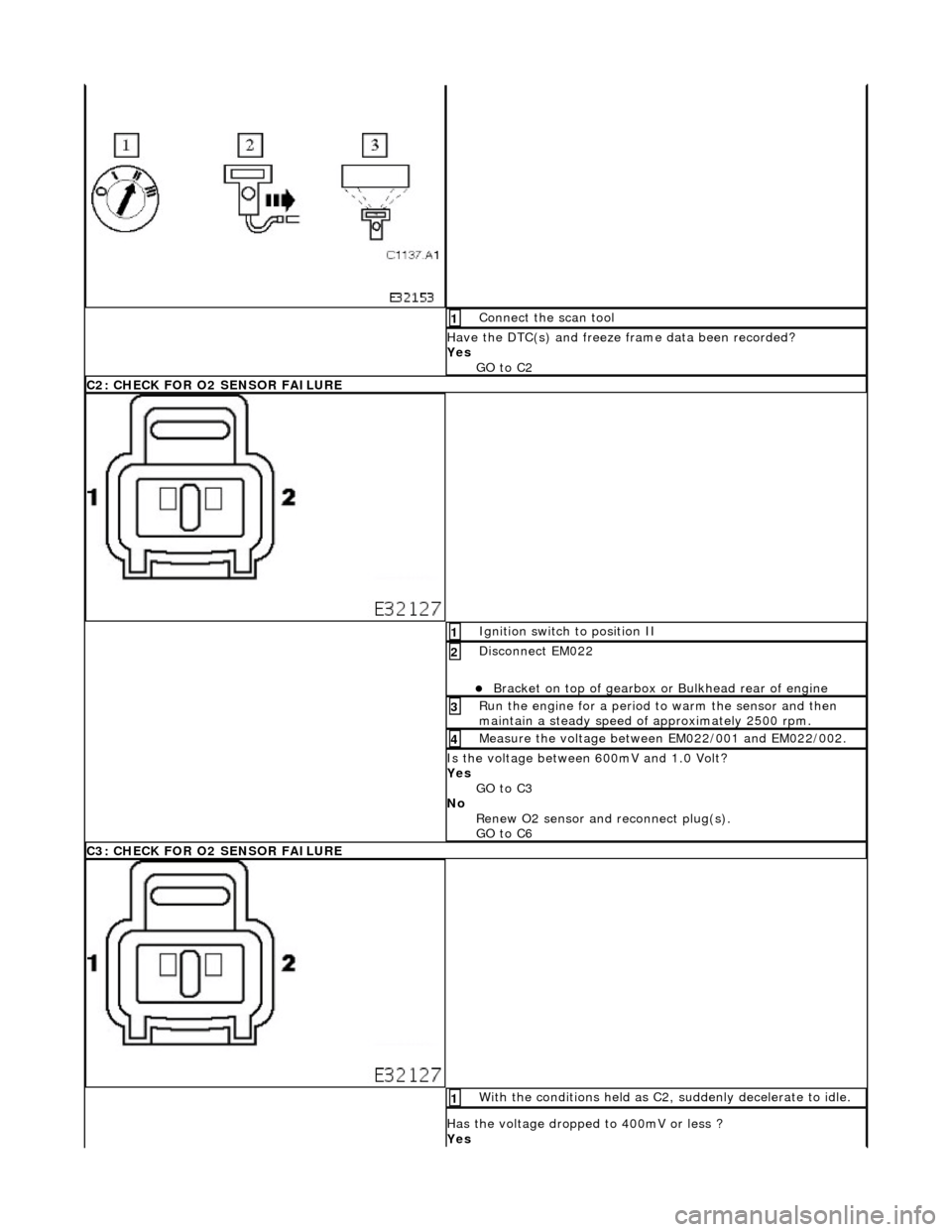
Connect the scan tool 1
Have the DTC(s) and freeze frame data been recorded?
Yes GO to C2
C2: CHECK FOR O2 SENSOR FAILURE
Ignition switch to position II 1
Disconnect EM022
Bracket on top of gearbox or Bulkhead rear of engine
2
Run the engine for a period to warm the sensor and then
maintain a steady speed of approximately 2500 rpm. 3
Measure the voltage between EM022/001 and EM022/002. 4
Is the voltage between 600mV and 1.0 Volt?
Yes
GO to C3
No Renew O2 sensor and reconnect plug(s).
GO to C6
C3: CHECK FOR O2 SENSOR FAILURE
With the conditions held as C2, suddenly decelerate to idle. 1
Has the voltage dropped to 400mV or less ?
Yes
Page 1561 of 2490
With EM012 and EM022 disconnected, measure the
resistance between EM012/017 and EM022/002. 1
Is the resistance < 0.5 OHM?
Yes GO to C8
No Inspect harness / connectors EM012 and EM022 for
corrosion, damaged / pushed back pins. Repair as necessary
and reconnect plug(s).
GO to C10
C8: O2 SENSOR SCREEN GROUND CONTINUITY
Page 1562 of 2490
With EM012 and EM022 disconnected, measure the
resistance between EM012/022 and EM022/001. 1
Is the resistance < 0.5 OHM?
Yes GO to C9
No Inspect harness / connectors EM012 and EM022 for
corrosion, damaged / pushed back pins.
Inspect harness / splice EM S08 for damage. Repair as
necessary and reconnect plug(s).
GO to C10
C9: O2 SENSOR SHORT CIRCUIT TO GROUND
Page 1563 of 2490
With EM022 disconnected measure the insulation resistance
between sensor pin 001 and sensor body. 1
Repeat for pin 002 and sensor body. 2
Is the resistance > 10 MOHM?
Yes GO to C11
No Renew the O2 sensor and reconnect all plugs.
GO to C10
C10: STOP
Perform appropriate service drive cycle and check for the
presence of DTC. 1
Has the fault code cleared?
Yes STOP
No Contact Jaguar Service
C11: SIGNAL GROUND 1 CONTINUITY
Page 1566 of 2490
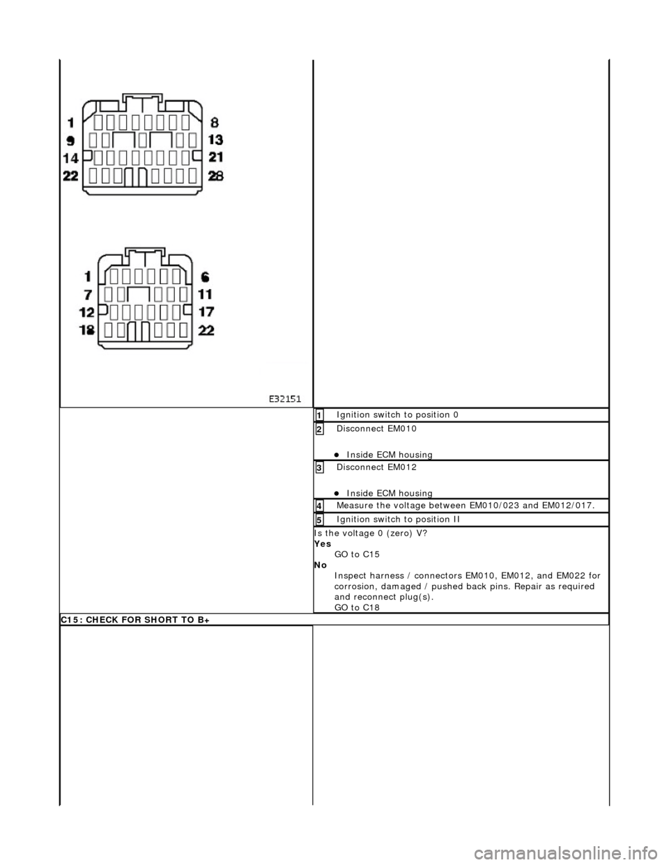
Ignition switch to position 0 1
Disconnect EM010
Inside ECM housing
2
Disconnect EM012
Inside ECM housing
3
Measure the voltage between EM010/023 and EM012/017. 4
Ignition switch to position II 5
Is the voltage 0 (zero) V?
Yes GO to C15
No Inspect harness / connectors EM010, EM012, and EM022 for
corrosion, damaged / pushed back pins. Repair as required
and reconnect plug(s).
GO to C18
C15: CHECK FOR SHORT TO B+
Page 1567 of 2490
Measure the voltage between EM010/023 and EM012/022. 1
Is the voltage 0 (zero) V?
Yes GO to C16
No Inspect harness / connectors EM010, EM012, and EM022 for
corrosion, damaged / pushed back pins. Repair as required
and reconnect plug(s).
GO to C18
C16: CHECK HARNESS SHORT TO GROUND


