em 022 JAGUAR X308 1998 2.G Workshop Manual
[x] Cancel search | Manufacturer: JAGUAR, Model Year: 1998, Model line: X308, Model: JAGUAR X308 1998 2.GPages: 2490, PDF Size: 69.81 MB
Page 934 of 2490
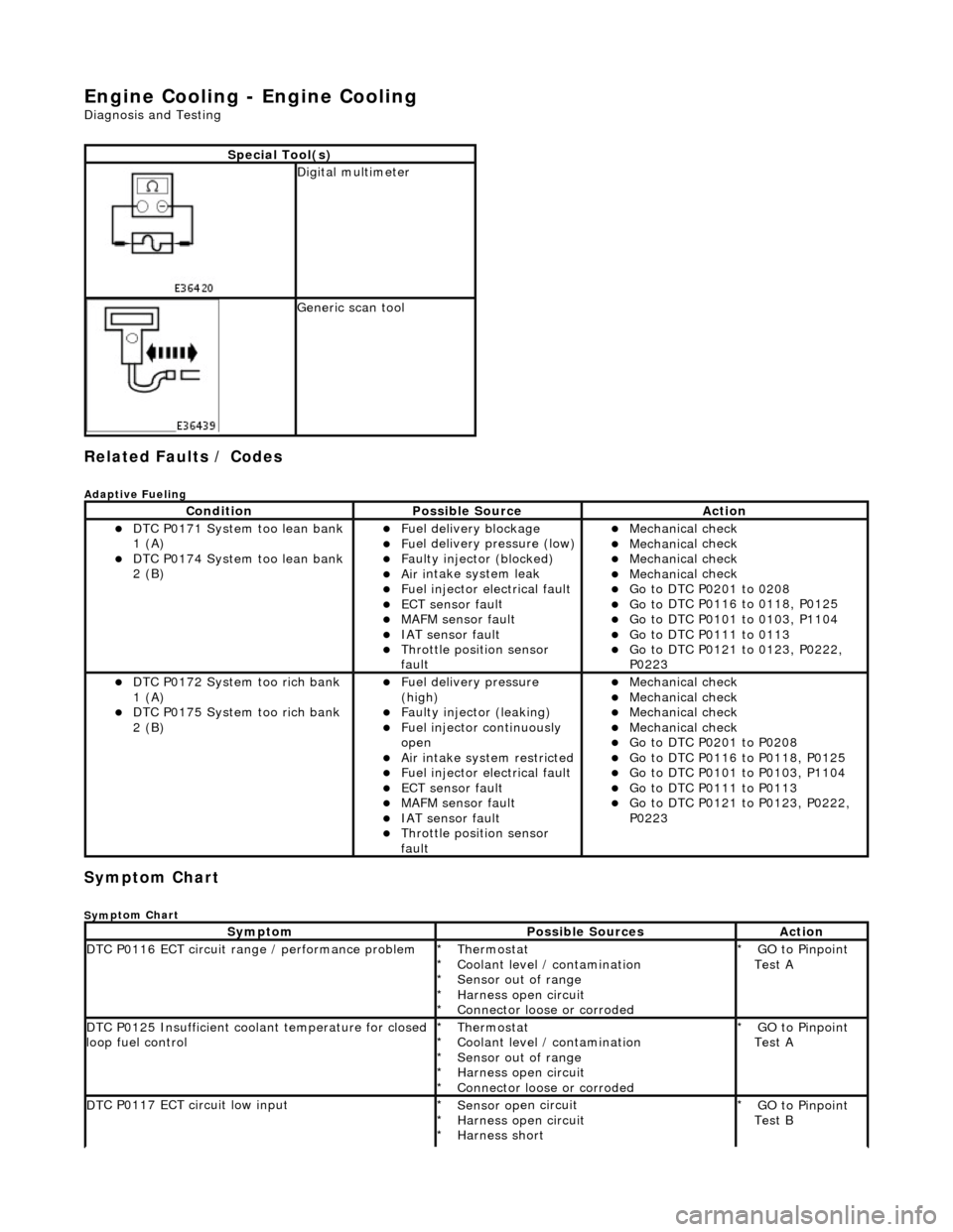
Engine Cooling - Engine Cooling
Diagn
osis and Testing
Related Faults / Codes
Adaptive
Fue
ling
Sym
p
tom Chart
Sy
m
ptom Chart
S
p
ecial Tool(s)
D
i
gital multimeter
Generi
c scan tool
Conditi
on
Possib
l
e Source
Acti
o
n
D
T
C P0171 System too lean bank
1 (A)
D T
C P0174 System too lean bank
2 (B)
Fuel delivery blockage Fu
el delivery pressure (low)
F
a
ulty injector (blocked)
Ai
r i
ntake system leak
F
u
el injector electrical fault
ECT sensor
faul
t
MAFM sensor fault IAT se
nsor fault
Thro
tt
le position sensor
fault
Mec hanica
l check
Mec
hanica
l check
Mec
hanica
l check
Mec
hanica
l check
Go t
o DTC P020
1 to 0208
Go t
o
DTC P0116 to 0118, P0125
Go t
o
DTC P0101 to 0103, P1104
Go t
o DTC P011
1 to 0113
Go t
o
DTC P0121 to 0123, P0222,
P0223
D T
C P0172 System too rich bank
1 (A)
D T
C P0175 System too rich bank
2 (B)
F u
el delivery pressure
(high)
F a
ulty injector (leaking)
F
u
el injector continuously
open
Ai r i
ntake system restricted
Fu
el injector electrical fault
ECT sensor
faul
t
MAFM sensor fault IAT sensor fault
Thrott
le position sensor
fault
Mec hanica
l check
Mec
hanica
l check
Mec
hanica
l check
Mec
hanica
l check
Go t
o DTC P020
1 to P0208
Go t
o
DTC P0116 to P0118, P0125
Go t
o
DTC P0101 to P0103, P1104
Go t
o DTC P011
1 to P0113
Go t
o
DTC P0121 to P0123, P0222,
P0223
Sy m
ptom
Possib
l
e Sources
Acti
o
n
D
T
C P0116 ECT circuit range / performance problem
Thermostat
Coo
l
ant level / contamination
Sensor out of range
Harness open circuit
Connector loose or corroded
*
*
*
*
*
GO to Pinpoint
Test A
*
D
T
C P0125 Insufficient coolant temperature for closed
loop fuel control
Thermostat
Coo l
ant level / contamination
Sensor out of range
Harness open circuit
Connector loose or corroded
*
*
*
*
*
GO to Pinpoint
Test A
*
D
T
C P0117 ECT circuit low input
Sensor o
p
en circuit
Harness open circuit
Harness short
*
*
*
GO to Pinpoint
Test B
*
Page 1023 of 2490
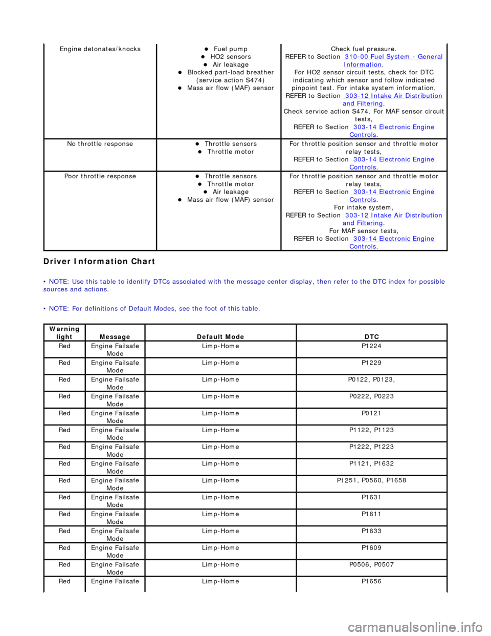
Driver Informa
tion Chart
•
NOTE: Use this table to identify DTCs associated with the me
ssage center display, then refer to the DTC index for possible
sources and actions.
• NOTE: For definitions of Default Modes, see the foot of this table.
Engine deton
ates/knocks
Fue
l pump
HO2 sensors Air leakage Blocked part-load breather
(
service action S474)
Mass ai
r flow (MAF) sensor
Chec
k fuel pressure.
REFER to Section 310
-00
Fuel System
- Gen
eral
Informati
on
.
F
or HO2 sensor circuit
tests, check for DTC
indicating which sensor and follow indicated
pinpoint test. For intake system information,
REFER to Section 303
-1
2 Intake Air Distribution
and F
iltering
.
Check service
action S474. For MAF sensor circuit
tests,
REFER to Section 303
-14 Elec
tronic Engine
Controls.
No
throttle response
Throttl
e sensors
Throttl
e motor
F
or throttle position se
nsor and throttle motor
relay tests,
REFER to Section 303
-14 Elec
tronic Engine
Controls.
Poor throttle responseThrottl
e sensors
Throttl
e motor
Air leakage Mass ai
r flow (MAF) sensor
F
or throttle position se
nsor and throttle motor
relay tests,
REFER to Section 303
-14 Elec
tronic Engine
Controls.
Fo
r intake system,
REFER to Section 303
-1
2 Intake Air Distribution
and F
iltering
.
For MAF
sensor tests,
REFER to Section 303
-14 Elec
tronic Engine
Controls.
Warning
lightMess
age
De
fault Mode
DT
C
Re
d
Engine
Failsafe
Mode
Lim
p-Home
P1224
Re
d
Engine
Failsafe
Mode
Lim
p-Home
P1229
Re
d
Engine
Failsafe
Mode
Lim
p-Home
P01
22, P0123,
Re
d
Engine
Failsafe
Mode
Lim
p-Home
P02
22, P0223
Re
d
Engine
Failsafe
Mode
Lim
p-Home
P0121
Re
d
Engine
Failsafe
Mode
Lim
p-Home
P11
22, P1123
Re
d
Engine
Failsafe
Mode
Lim
p-Home
P12
22, P1223
Re
d
Engine
Failsafe
Mode
Lim
p-Home
P11
21, P1632
Re
d
Engine
Failsafe
Mode
Lim
p-Home
P12
51, P0560, P1658
Re
d
Engine
Failsafe
Mode
Lim
p-Home
P1631
Re
d
Engine
Failsafe
Mode
Lim
p-Home
P1611
Re
d
Engine
Failsafe
Mode
Lim
p-Home
P1633
Re
d
Engine
Failsafe
Mode
Lim
p-Home
P1609
Re
d
Engine
Failsafe
Mode
Lim
p-Home
P05
06, P0507
Re
d
Engine
Failsafe
Lim
p-Home
P1656
Page 1081 of 2490

•
NOTE: For definitions of Default Modes, see the foot of this table.
Warning
lightMess
age
De
fault Mode
DT
C
Re
d
Engine
Failsafe
Mode
Lim
p-Home
P1224
Re
d
Engine
Failsafe
Mode
Lim
p-Home
P1229
Re
d
Engine
Failsafe
Mode
Lim
p-Home
P01
22, P0123,
Re
d
Engine
Failsafe
Mode
Lim
p-Home
P02
22, P0223
Re
d
Engine
Failsafe
Mode
Lim
p-Home
P0121
Re
d
Engine
Failsafe
Mode
Lim
p-Home
P11
22, P1123
Re
d
Engine
Failsafe
Mode
Lim
p-Home
P12
22, P1223
Re
d
Engine
Failsafe
Mode
Lim
p-Home
P11
21, P1632
Re
d
Engine
Failsafe
Mode
Lim
p-Home
P12
51, P0560, P1658
Re
d
Engine
Failsafe
Mode
Lim
p-Home
P1631
Re
d
Engine
Failsafe
Mode
Lim
p-Home
P1611
Re
d
Engine
Failsafe
Mode
Lim
p-Home
P1633
Re
d
Engine
Failsafe
Mode
Lim
p-Home
P1609
Re
d
Engine
Failsafe
Mode
Lim
p-Home
P05
06, P0507
Re
d
Engine
Failsafe
Mode
Lim
p-Home
P1656
Re
d
Engine
Failsafe
Mode
Engine
shut-down when combined with other
throttle failures
P1254
Re
d
Engine
Failsafe
Mode
Engine
shut-down when combined with other
throttle failures
P1250
Ambe
r
Engine
Failsafe
Mode
Cruis
e inhibited
P1516
Ambe
r
Engine
Failsafe
Mode
Cruis
e inhibited
P1517
Ambe
r
Engine
Failsafe
Mode
Cruis
e inhibited
P1571
Ambe
r
Engine
Failsafe
Mode
Cruis
e inhibited
P1696
Ambe
r
Engine
Failsafe
Mode
Cruis
e inhibited
P0568
Ambe
r
Engine
Failsafe
Mode
Cruis
e inhibited
P0570
Ambe
r
Engine
Failsafe
Mode
Cruis
e inhibited
P0569
Ambe
r
Engine
Failsafe
Mode
Cruis
e inhibited
P0567
Ambe
r
Engine
Failsafe
Mode
Cruis
e inhibited
P0566
Ambe
r
Engine
Failsafe
Mode
Cruis
e inhibited
P1697
Re
d
Re
stricted
Performance
Li
mp-Home unavailable. Reverse throttle
progression enabled
P05
60, P1254
Ambe
r
Re
stricted
Performance
Li
mp-Home unavailable. Reverse throttle
progression enabled. High idle speed
P12
50, P1254
Re
d
Re
stricted
Performance
Li
mp-Home unavailable. Reverse throttle
progression enabled
P1250
Page 1181 of 2490
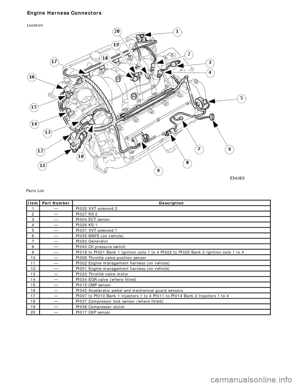
P
arts List
It
em
Par
t Number
De
scription
1—PI032
VVT solenoid 2
2—PI027
KS 2
3—PI004
ECT sensor
4—PI026
KS 1
5—PI031
VVT solenoid 1
6—PI035
MAFS (on vehicle)
7—PI050
Generator
8—PI040
Oil pressure switch
9—PI018
to PI021 Bank 1 Ignition coils 1 to 4
PI022 to PI025 Bank 2 Ignition coils 1 to 4
10—PI006
Throttle valve position sensor
11—PI002 En
gine management harness (on vehicle)
12—PI001 En
gine management harness (on vehicle)
13—PI033
Throttle valve motor
14—PI034
EGR valve (where fitted)
15—PI015 CM
P sensor
16—PI042
Accelerator pedal and
mechanical guard sensors
17—PI007
to PI010 Bank 1 Injectors 1 to 4 PI011 to PI014 Bank 2 Injectors 1 to 4
18—PI037
Compressor lock
sensor (where fitted)
19—PI036
Compressor clutch
20—PI017 CK
P sensor
E
ngine Harness Connectors
Location
Page 1193 of 2490
Re
d
Engine
Failsafe
Mode
Lim
p-Home
P1224
Re
d
Engine
Failsafe
Mode
Lim
p-Home
P1229
Re
d
Engine
Failsafe
Mode
Lim
p-Home
P01
22, P0123,
Re
d
Engine
Failsafe
Mode
Lim
p-Home
P02
22, P0223
Re
d
Engine
Failsafe
Mode
Lim
p-Home
P0121
Re
d
Engine
Failsafe
Mode
Lim
p-Home
P11
22, P1123
Re
d
Engine
Failsafe
Mode
Lim
p-Home
P12
22, P1223
Re
d
Engine
Failsafe
Mode
Lim
p-Home
P11
21, P1632
Re
d
Engine
Failsafe
Mode
Lim
p-Home
P12
51, P0560, P1658
Re
d
Engine
Failsafe
Mode
Lim
p-Home
P1631
Re
d
Engine
Failsafe
Mode
Lim
p-Home
P1611
Re
d
Engine
Failsafe
Mode
Lim
p-Home
P1633
Re
d
Engine
Failsafe
Mode
Lim
p-Home
P1609
Re
d
Engine
Failsafe
Mode
Lim
p-Home
P05
06, P0507
Re
d
Engine
Failsafe
Mode
Lim
p-Home
P1656
Re
d
Engine
Failsafe
Mode
Engine
shut-down when combined with other
throttle failures
P1254
Re
d
Engine
Failsafe
Mode
Engine
shut-down when combined with other
throttle failures
P1250
Ambe
r
Engine
Failsafe
Mode
Cruis
e inhibited
P1516
Ambe
r
Engine
Failsafe
Mode
Cruis
e inhibited
P1517
Ambe
r
Engine
Failsafe
Mode
Cruis
e inhibited
P1571
Ambe
r
Engine
Failsafe
Mode
Cruis
e inhibited
P1696
Ambe
r
Engine
Failsafe
Mode
Cruis
e inhibited
P0568
Ambe
r
Engine
Failsafe
Mode
Cruis
e inhibited
P0570
Ambe
r
Engine
Failsafe
Mode
Cruis
e inhibited
P0569
Ambe
r
Engine
Failsafe
Mode
Cruis
e inhibited
P0567
Ambe
r
Engine
Failsafe
Mode
Cruis
e inhibited
P0566
Ambe
r
Engine
Failsafe
Mode
Cruis
e inhibited
P1697
Re
d
Re
stricted
Performance
Li
mp-Home unavailable. Reverse throttle
progression enabled
P05
60, P1254
Ambe
r
Re
stricted
Performance
Li
mp-Home unavailable. Reverse throttle
progression enabled. High idle speed
P12
50, P1254
Re
d
Re
stricted
Performance
Li
mp-Home unavailable. Reverse throttle
progression enabled
P1250
Ambe
r
Re
stricted
Performance
Engine
Speed Limit (runs normally, limited to
3000 rpm)
P01
16, P0117, P0118, P0125
Ambe
r
Re
stricted
Performance
Engine
Speed Limit (runs normally, limited to
3000 rpm)
P01
01, P0102, P0103, P0104
Ambe
r
Re
stricted
Engine
Speed Limit (runs normally, limited to
P03
00, P0301, P0302, P0303, P0304, P0305,
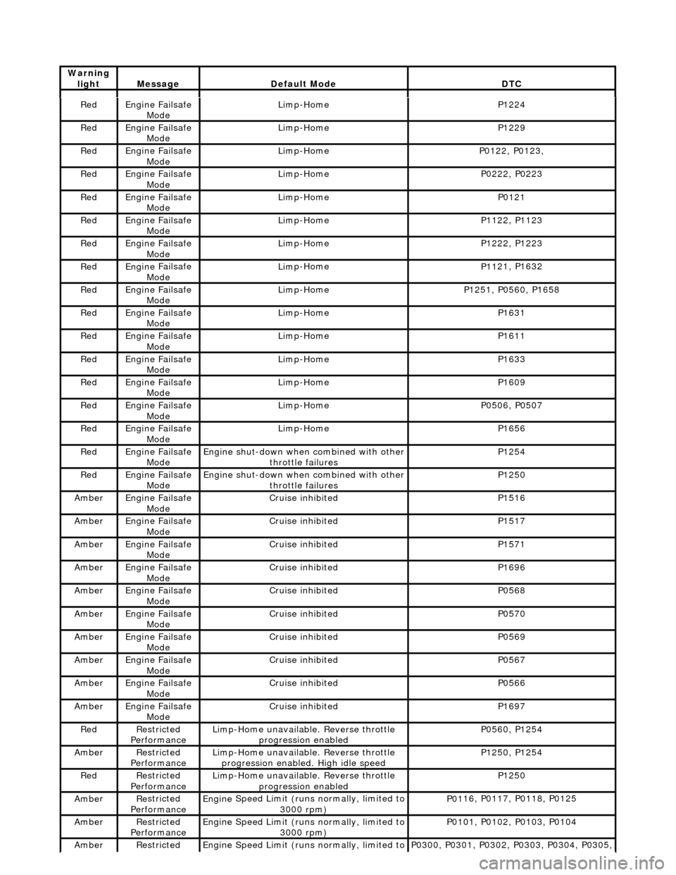
Warning
lightMess
age
De
fault Mode
DT
C
Page 1199 of 2490
cyl 8
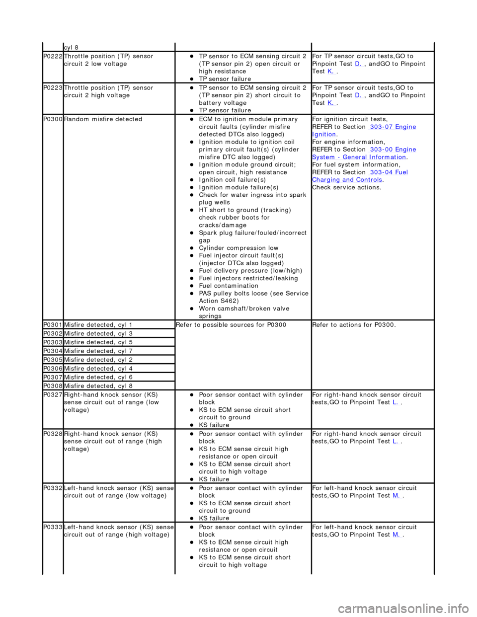
P0222Thro
ttle position (TP) sensor
circuit 2 low voltage
TP se
nsor to ECM sensing circuit 2
(TP sensor pin 2) open circuit or
high resistance
TP sensor
failure
F
or TP sensor circ
uit tests,GO to
Pinpoint Test D.
, andG
O to Pinpoint
Test K.
.
P0223Thro
ttle position (TP) sensor
circuit 2 high voltage
TP se
nsor to ECM sensing circuit 2
(TP sensor pin 2) short circuit to
battery voltage
TP sensor
failure
F
or TP sensor circ
uit tests,GO to
Pinpoint Test D.
, andG
O to Pinpoint
Test K.
.
P0300Ran
dom misfire detected
ECM to
ignition module primary
circuit faults (cylinder misfire
detected DTCs also logged)
Igni
tion module to ignition coil
primary circuit fault(s) (cylinder
misfire DTC also logged)
Ignition modu
le ground circuit;
open circuit, hi gh resistance
Ignition coil
failure(s)
Ignition modul
e failure(s)
Check f
or water ingress into spark
plug wells
HT sho
rt to ground (tracking)
check rubber boots for
cracks/damage
Spark plug
failure/fouled/incorrect
gap
Cy
linder compression low
F
uel injector circuit fault(s)
(injector DTCs also logged)
F
uel delivery pressure (low/high)
F
uel injectors restricted/leaking
Fuel contamination
P
AS pulley bolts loose (see Service
Action S462)
W
orn camshaft/broken valve
springs
F
or ignition circuit tests,
REFER to Section 303
-07
Engine
Ignition.
F
or engine information,
REFER to Section 303
-00
Engine
Sy
stem
- General
Information
.
F
or fuel system information,
REFER to Section 303
-04
Fuel
Charging and Con
trols
.
Check service
actions.
P0301Mis
fire detected, cyl 1
R
efer to possible sources for P0300
R
efer to actions for P0300.
P0302Mis
fire detected, cyl 3
P0303Mis
fire detected, cyl 5
P0304Mis
fire detected, cyl 7
P0305Mis
fire detected, cyl 2
P0306Mis
fire detected, cyl 4
P0307Mis
fire detected, cyl 6
P0308Mis
fire detected, cyl 8
P0327Right
-hand knock sensor (KS)
sense circuit out of range (low
voltage)
Poor sensor cont
act with cylinder
block
KS to
ECM sense circuit short
circuit to ground
KS fai
lure
F
or right-hand knock sensor circuit
tests,GO to Pinpoint Test L.
.
P0328Right
-hand knock sensor (KS)
sense circuit out of range (high
voltage)
Poor sensor cont
act with cylinder
block
KS to EC
M sense circuit high
resistance or open circuit
KS to
ECM sense circuit short
circuit to high voltage
KS fai
lure
F
or right-hand knock sensor circuit
tests,GO to Pinpoint Test L.
.
P0332Left-hand knock sens
or (KS) sense
circuit out of range (low voltage)
Poor sensor cont
act with cylinder
block
KS to
ECM sense circuit short
circuit to ground
KS fai
lure
F
or left-hand knoc
k sensor circuit
tests,GO to Pinpoint Test M.
.
P0333Left-hand knock sens
or (KS) sense
circuit out of range (high voltage)
Poor sensor cont
act with cylinder
block
KS to EC
M sense circuit high
resistance or open circuit
KS to
ECM sense circuit short
circuit to high voltage
F
or left-hand knoc
k sensor circuit
tests,GO to Pinpoint Test M.
.
Page 1215 of 2490

normal operation
.
No INSTALL a new catalyst monitor sensor.
REFER to Catalyst Monitor Sensor LH
in this section.
CLEAR the DTC. TEST the syst em for normal operation.
P
INPOINT TEST K : DTC P0222, P0223; THRO
TTLE POSITION (TP) SENSOR CIRCUIT 2 LOW
VOLTAGE
TE
ST
CONDITIONS
D
ETAILS/RESULTS/ACTIONS
K
1: CHECK TP SENSOR 2 SENSE CIRCUIT FOR HIGH RESISTANCE
Di
sconnect the battery negative terminal.
1
Disc
onnect the TP sensor electrical connector, PI06.
2
D
isconnect the ECM electrical connector, EM11.
3
Me
asure the resistance between PI06, pin 02 (G) and EM11, pin 10 (G).
4
Is th
e resistance greater than 5 ohms?
Yes REPAIR the high resistance circui t. For additional information, refer to the wiring diagrams. CLEAR
the DTC. TEST the system for normal operation.
No GO to K2
.
K
2: CHECK TP SENSOR 2 SENSE CIRC
UIT FOR SHORT TO HIGH VOLTAGE
R
econnect the battery negative terminal.
1
Turn the ignition swi
tch to the ON
position.
2
M
easure the voltage between PI06, pin 02 (G) and GROUND.
3
Is th
e voltage greater than 5 volts?
Yes REPAIR the short circuit. For addi tional information, refer to the wiring diagrams. CLEAR the DTC.
TEST the system for normal operation.
No INSTALL a new TP sensor.
REFER to Throttle Position (TP) Sensor
in this section.
CLEAR the DTC. TEST the system for normal operation.
PI
NPOINT TEST L : DTC P0327, P0328; RIGHT-HA
ND KNOCK SENSOR (KS) CIRCUIT OUT OF RANGE
(LOW VOLTAGE)
•
NOTE: Before commencing this
test, make sure that the sensor is making a good electrical contact with the cylinder
block. See 'possible causes'.
TE
ST
CONDITIONS
D
ETAILS/RESULTS/ACTIONS
L
1: CHECK THE KS SENSE CIRCUIT FOR HIGH RESISTANCE
Di
sconnect the battery negative terminal.
1
Di
sconnect the KS electrical connector, PI26.
2
D
isconnect the ECM electrical connector, EM13.
3
Me
asure the resistance between PI26, pin 01 (S) and EM13, pin 18 (S).
4
Is th
e resistance greater than 5 ohms?
Yes REPAIR the high resistance circui t. For additional information, refer to the wiring diagrams. CLEAR
the DTC. TEST the system for normal operation.
No GO to L2
.
L
2: CHECK THE KS SENSE CIRCUIT FOR SHORT TO HIGH VOLTAGE
Turn the ignition swi
tch to the ON
position.
1
R
econnect the battery negative terminal.
2
Meas
ure the voltage between PI26, pin 01 (S) and GROUND.
3
Is th
e voltage greater than 3 volts?
Yes REPAIR the short circuit. For addi tional information, refer to the wiring diagrams. CLEAR the DTC.
TEST the system for normal operation.
No GO to L3
.
Page 1272 of 2490
3.3. Gradient: Under specific speeds and loads
4. 4. Cruise: During cruise control
5. 5. Manual: Shift map when the LH side of the 'J gate' is used
Three specific condition shift maps have a higher priority than the two base shift maps and will intervene when appropriate
conditions prevail for traction, gradient or cruise.
When traction control (engine or brake system derived) is operational the TCM will implement the traction map to maximise
control of wheel slip.
The gradient maps are intended to enhance vehicle drivability when towing or climbing a gradient. The TCM will implement
the maps when increased driving resistan ce is detected and enhanced drivability, cooling and increa sed performance is
appropriate.
The cruise map is intended to minimize unwanted gearshifts and 'hunting' and is activated when cruising near to the set
speed, or resuming.
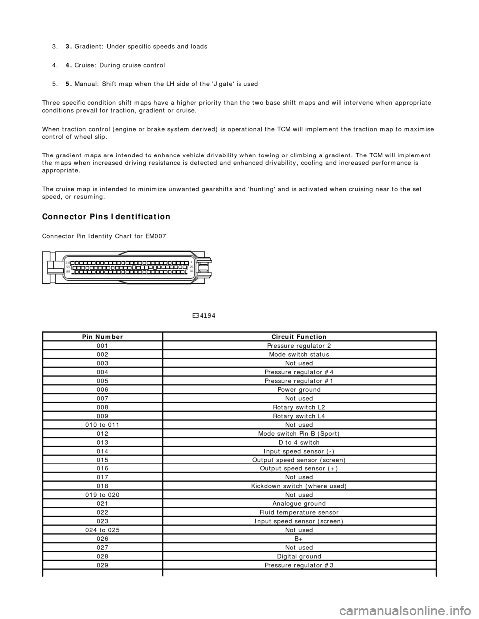
Connector Pins Identification
Connector Pin Identity Chart for EM007
Pin NumberCircuit Function
001Pressure regulator 2
002Mode switch status
003Not used
004Pressure regulator #4
005Pressure regulator #1
006Power ground
007Not used
008Rotary switch L2
009Rotary switch L4
010 to 011Not used
012Mode switch Pin B (Sport)
013D to 4 switch
014Input speed sensor (-)
015Output speed sensor (screen)
016Output speed sensor (+)
017Not used
018Kickdown switch (where used)
019 to 020Not used
021Analogue ground
022Fluid temperature sensor
023Input speed sensor (screen)
024 to 025Not used
026B+
027Not used
028Digital ground
029Pressure regulator #3
Page 1541 of 2490

With EM012 and EM021 disconnected, measure the
resistance between EM012/022 and EM021/004 1
Is the resistance < 0.5 OHM?
Yes GO to A14
No Inspect harness / connectors EM012, EM021 and splice
EMS08 for corrosion, damaged / pushed back pins. Repair as
required and reconnect plug(s).
GO to A18
A14: CHECK FOR SHORT TO B+
Page 1542 of 2490

Ignition switch to position 0 1
Disconnect EM010 and EM012
Inside ECM housing
2
Ignition switch to position II 3
Measure the voltage between EM010/023 and EM012/015 4
Is the voltage 0 (zero) V?
Yes GO to A15
No Inspect harness / connectors EM010, EM012, and EM021 for
corrosion, damaged / pushed back pins. Repair as required
and reconnect plug(s).
GO to A18
A15: CHECK FOR SHORT TO B+
Measure the voltage between EM010/023 and EM012/022 1