instrument panel JAGUAR X308 1998 2.G User Guide
[x] Cancel search | Manufacturer: JAGUAR, Model Year: 1998, Model line: X308, Model: JAGUAR X308 1998 2.GPages: 2490, PDF Size: 69.81 MB
Page 1788 of 2490
Heating and Ventilation - Heater Core and Evaporator Core Housing
Removal and Installation
Removal
1. Disconnect battery ground cable (IMPORTANT, see SRO
86.15.19 for further information).
2. Recover refrigerant from air co nditioning system; refer to
82.30.30.
3. Drain radiator coolant only; refer to 26.10.01 or (SC)
26.10.01.
4. Remove instrument panel for access, refer to 76.46.01.
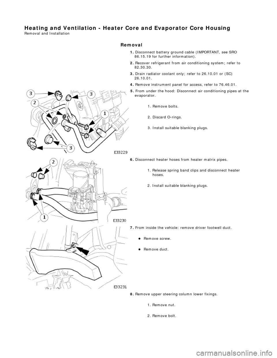
5. From under the hood: Disconnect air conditioning pipes at the
evaporator.
1. Remove bolts.
2. Discard O-rings.
3. Install suitable blanking plugs.
6. Disconnect heater hoses from heater matrix pipes.
1. Release spring band clips and disconnect heater hoses.
2. Install suitable blanking plugs.
7. From inside the vehicle: re move driver footwell duct.
Remove screw.
Remove duct.
8. Remove upper steering column lower fixings.
1. Remove nut.
2. Remove bolt.
Page 1837 of 2490
System Self-test
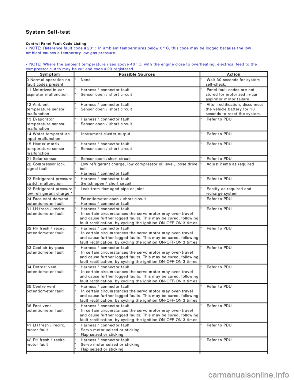
Control Panel Fault Code Listing • NOTE: Reference fault code #23*: In ambient temperatures below 0° C, this code may be logged because the low
ambient causes a tempor ary low gas pressure.
• NOTE: Where the ambient temperature rises above 40° C, with the engine close to overheating, electrical feed to the
compressor clutch may be cut and code #23 registered.
SymptomPossible SourcesAction
0 Normal operation no
fault codes presentNone
*Wait 30 seconds for system
self-check.
*
11 Motorized in-car
aspirator malfunctionHarness / connector fault
Sensor open / short circuit
*
*Panel fault codes are not
stored for motorized in-car
aspirator motor failure.
*
12 Ambient
temperature sensor
malfunctionHarness / connector fault
Sensor open / short circuit
*
*After rectification, disconnect
the vehicle battery for 10
seconds to reset the system.
*
13 Evaporator
temperature sensor
malfunctionHarness / connector fault
Sensor open / short circuit
*
*Refer to PDU
*
14 Water temperature
input malfunctionInstrument cl uster output
*Refer to PDU
*
15 Heater matrix
temperature sensor
malfunctionHarness / connector fault
Sensor open / short circuit
*
*Refer to PDU
*
21 Solar sensorSensor open /short circuit
*Refer to PDU
*
22 Compressor lock
signal faultLow refrigerant charge, low compressor oil level, loose drive
belt Harness / connector fault
*
*Adjust items as required
*
23 Refrigerant pressure
switch malfunctionHarness / connector fault
Switch open / short circuit
*
*Refer to PDU
*
23 Refrigerant pressure
low refrigerant charge * Leak from damaged pipe or joint
*Rectify as required and
recharge system
*
24 Face vent demand
potentiometer faultPotentiometer open / short circuit
Harness / connector fault
*
*Refer to PDU
*
31 LH fresh / recirc.
potentiometer faultHarness / connector fault
In certain circumstances the servo motor may over-travel
and cause further logged faults. This may be cured, following
fault rectification, by cycling the ignition ON-OFF-ON 3 times
*
*Refer to PDU
*
32 RH fresh / recirc.
potentiometer faultHarness / connector fault
In certain circumstances the servo motor may over-travel
and cause further logged faults. This may be cured, following
fault rectification, by cycling the ignition ON-OFF-ON 3 times
*
*Refer to PDU
*
33 Cool air by-pass
potentiometer faultHarness / connector fault
In certain circumstances the servo motor may over-travel
and cause further logged faults. This may be cured, following
fault rectification, by cycling the ignition ON-OFF-ON 3 times
*
*Refer to PDU
*
34 Defrost vent
potentiometer faultHarness / connector fault
In certain circumstances the servo motor may over-travel
and cause further logged faults. This may be cured, following
fault rectification, by cycling the ignition ON-OFF-ON 3 times
*
*Refer to PDU
*
35 Centre vent
potentiometer faultHarness / connector fault
In certain circumstances the servo motor may over-travel
and cause further logged faults. This may be cured, following
fault rectification, by cycling the ignition ON-OFF-ON 3 times
*
*Refer to PDU
*
36 Foot vent
potentiometer faultHarness / connector fault
In certain circumstances the servo motor may over-travel
and cause further logged faults. This may be cured, following
fault rectification, by cycling the ignition ON-OFF-ON 3 times
*
*Refer to PDU
*
41 LH fresh / recirc.
motor faultHarness / connector fault
Servo motor seized or sticking
Flap seized or sticking
*
*
*Refer to PDU
*
42 RH fresh / recirc.
motor faultHarness / connector fault
Servo motor seized or sticking
Flap seized or sticking
*
*
*Refer to PDU
*
Page 1842 of 2490
Control Components - Cold Air Bypass Blend Door Actuator
Removal and Installation
Removal
Installation
1.
Remove instrument panel for access; refer to 76.46.01.
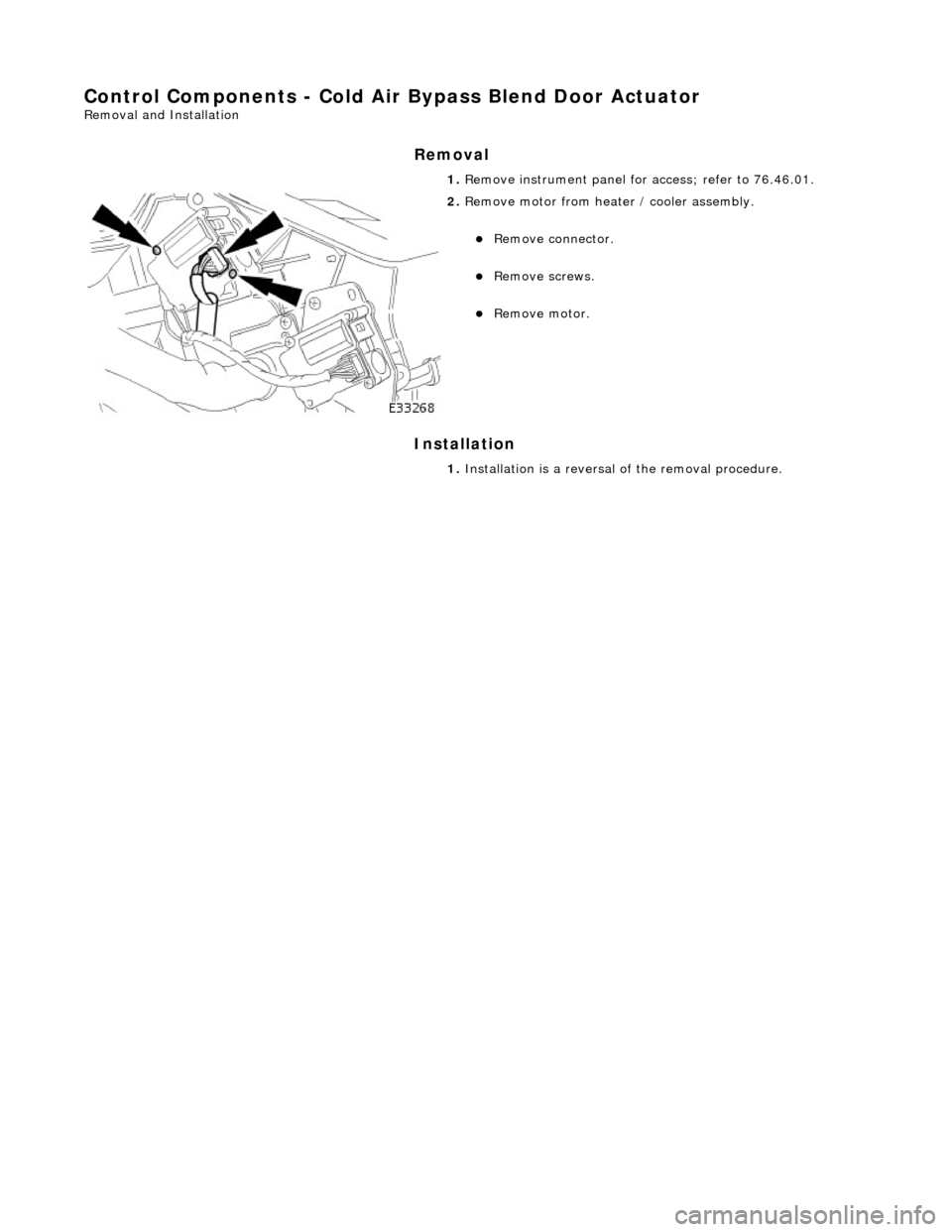
2. Remove motor from heater / cooler assembly.
Remove connector.
Remove screws.
Remove motor.
1. Installation is a reversal of the removal procedure.
Page 1844 of 2490
Control Components - Footwell Vent/Duct Blend Door Actuator
Removal and Installation
Removal
Installation
1.
Remove instrument panel for access; refer to 76.46.01.
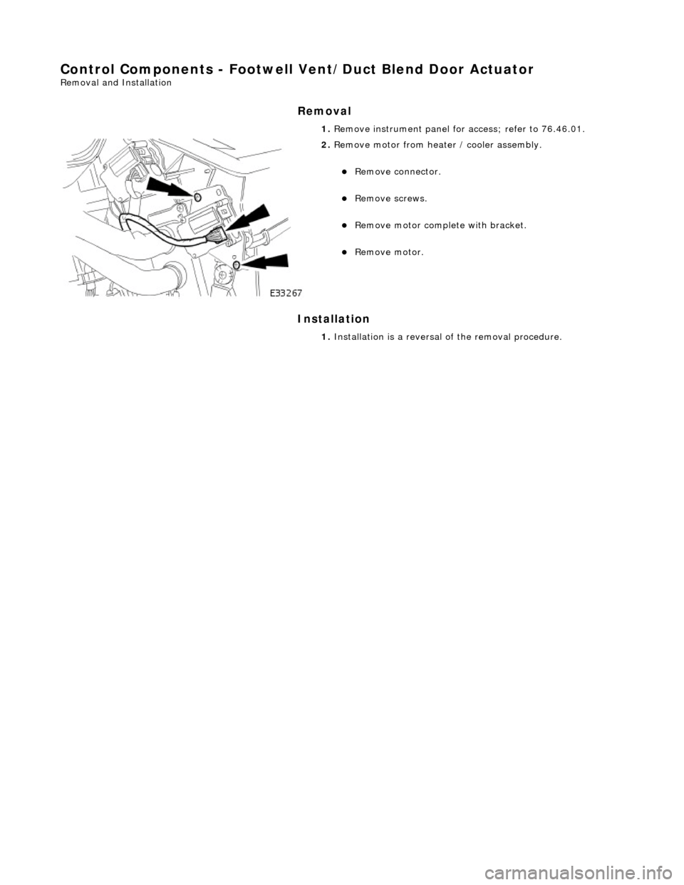
2. Remove motor from heater / cooler assembly.
Remove connector.
Remove screws.
Remove motor complete with bracket.
Remove motor.
1. Installation is a reversal of the removal procedure.
Page 1845 of 2490
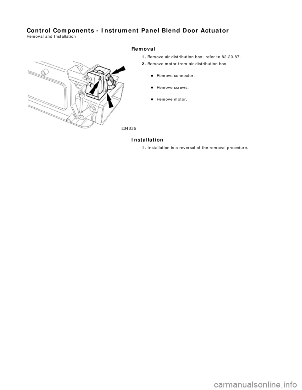
Control Components - Instrument Panel Blend Door Actuator
Removal and Installation
Removal
Installation
1.
Remove air distribution box; refer to 82.20.87.
2. Remove motor from air distribution box.
Remove connector.
Remove screws.
Remove motor.
1. Installation is a reversal of the removal procedure.
Page 1852 of 2490

Instrument Cluster and Panel Illumination - Instrument Cluster and Panel
Illumination
Description and Operation
Details on the Instrument Cluster and Panel Illumination can be found in sections 413-01, 413-06, 413-07 and 413-08.
Page 1853 of 2490
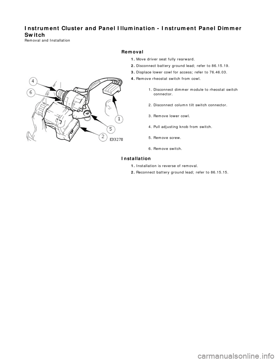
Instrument Cluster and Panel Illumination - Instrument Panel Dimmer
Switch
Removal and Installation
Removal
Installation
1.
Move driver seat fully rearward.
2. Disconnect battery ground lead; refer to 86.15.19.
3. Displace lower cowl for access; refer to 76.46.03.
4. Remove rheostat sw itch from cowl.
1. Disconnect dimmer module to rheostat switch connector.
2. Disconnect column tilt switch connector.
3. Remove lower cowl.
4. Pull adjusting knob from switch.
5. Remove screw.
6. Remove switch.
1. Installation is reverse of removal.
2. Reconnect battery ground lead; refer to 86.15.15.
Page 1857 of 2490
Instrume
nt Cluster - Instrument Cluster
Re
moval and Installation
Remov
al
1.
Adjust steer
ing column to full
y extended and lowered position.
2. Remove battery cover and disc onnect ground cable from
battery terminal. Refer to 86.15.19.
3. Remove veneer from instrument panel. Refer to 76.47.24.
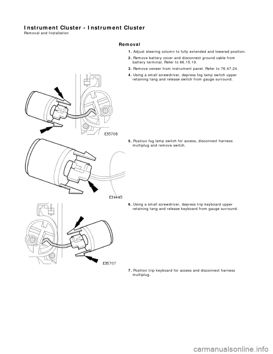
4. Using a small
screwdriver, de
press fog lamp switch upper
retaining tang and release sw itch from gauge surround.
5. Position fog l
amp switch fo
r access, disconnect harness
multiplug and remove switch.
6. Using a small
screwdriver, depress trip keyboard upper
retaining tang and release ke yboard from gauge surround.
7. Position trip keyboard for ac cess and disconnect harness
multiplug.
Page 1867 of 2490
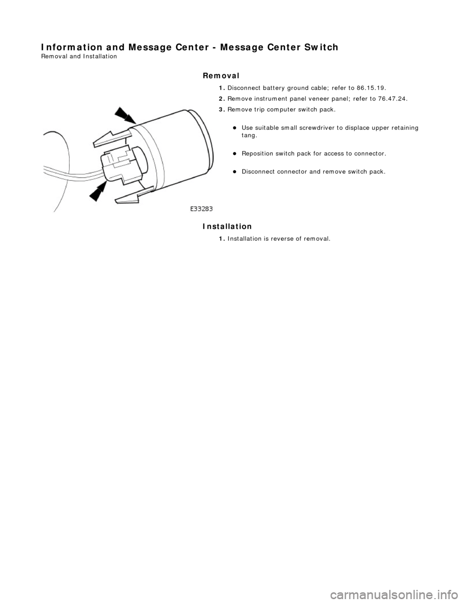
Information and Message Center - Message Center Switch
Removal and Installation
Removal
Installation
1.
Disconnect battery ground cable; refer to 86.15.19.
2. Remove instrument panel veneer panel; refer to 76.47.24.
3. Remove trip computer switch pack.
Use suitable small screwdriver to displace upper retaining
tang.
Reposition switch pack for access to connector.
Disconnect connector and remove switch pack.
1. Installation is reverse of removal.
Page 1925 of 2490
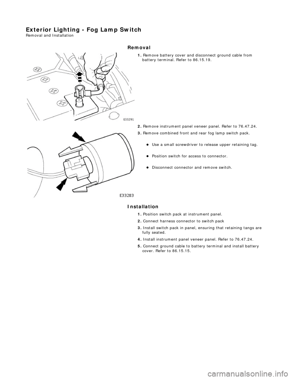
Exterior Lighting - Fog Lamp Switch
Removal and Installation
Removal
Installation
1. Remove battery cover and disc onnect ground cable from
battery terminal. Refer to 86.15.19.
2. Remove instrument pa nel veneer panel. Refer to 76.47.24.
3. Remove combined front and rear fog lamp switch pack.
Use a small screwdriver to re lease upper retaining tag.
Position switch for access to connector.
Disconnect connector and remove switch.
1. Position switch pack at instrument panel.
2. Connect harness connector to switch pack
3. Install switch pack in panel, ensuring that retaining tangs are
fully seated.
4. Install instrument panel veneer panel. Refer to 76.47.24.
5. Connect ground cable to batter y terminal and install battery
cover. Refer to 86.15.15.