heater JAGUAR X308 1998 2.G Workshop Manual
[x] Cancel search | Manufacturer: JAGUAR, Model Year: 1998, Model line: X308, Model: JAGUAR X308 1998 2.GPages: 2490, PDF Size: 69.81 MB
Page 21 of 2490

В В В В В В В В В В В В В В В В В В В В AirВ Distributio nВ and В Filt
ering
В
В В В В В В В В В В В В В В В В Diagnosis В and В Testing В
В В В В В В В В В В В В В В В В В В В В AirВ Distribution В and В Filtering В
В В В В В В В В В В В В В В В В RemovalВ and В Installation В
В В В В В В В В В В В В В В В В В В В В CenterВ Registers В (82.20.38) В
В В В В В В В В В В В В В В В В В В В В DriverВ Side В Blower В Motor В (82.25.56) В
В В В В В В В В В В В В В В В В В В В В PassengerВ Side В Blower В Motor В (82.25.55) В
В В В В В В В В В В В В В В В В В В В В PlenumВ Chamber В (82.20.87) В
В
В В В В В В В В В В В В 412‐02: В Heating В and В Ventilation В
В В В В В В В В В В В В В В В В Description В and В Operation В
В В В В В В В В В В В В В В В В В В В В HeatingВ and В Ventilation В
В В В В В В В В В В В В В В В В В В В
В В В В В В В В В В В В В В В В В В В В В
В В
В В В В В В В В В В В В В В В В Removal
В and В Installation В
В В В В В В В В В В В В В В В В В В В В Heater
В Core В (80.20.29) В
В В В В В В В В В В В В В В В В В В В В Heater
В Core В and В Evaporator В Core В Housing В (82.25.21) В
В
В В В В В В В В В В В В 412
‐03: В Air В Conditioning В
В В В В В В В В В В В В В В В В Description
В and В Operation В
В В В В В В В В В В В В В В В В В В В В AirВ
Conditioning В
В В В В В В В В В В В В В В В В Diagnosis
В and В Testing В
В В В В В В В В В В В В В В В В В В В В AirВ
Conditioning В
В В В В В В В В В В В В В В В В Removal
В and В Installation В
В В В В В В В В В В В В В В В В В В В В AirВ
Conditioning В (A/C) В CompressorВ (82.10.20)В
В В В В В В В В В В В В В В В В В В В В Condenser
В Core В (82.15.07) В
В В В В В В В В В В В В В В В В В В В В Evaporator
В Core В (82.25.20) В
В В В В В В В В В В В В В В В В В В В В Press
ureВ Cutoff В Switch В (82.10.32) В
В В В В В В В В В В В В В В В В В В В В Receiver
В Drier В (82.17.01) В
В
В В В В В В В В В В В В 412
‐04: В Control В Components В
В В В В В В В В В В В В В В В В Description
В and В Operation В
В В В В В В В В В В В В В В В В В В В В ControlВ
Components В
В В В В В В В В В В В В В В В В Diagnosis
В and В Testing В
В В В В В В В В В В В В В В В В В В В В ControlВ
Components В
В В В В В В В В В В В В В В В В Removal
В and В Installation В
В В В В В В В В В В В В В В В В В В В В AirВ
Discharge В Temperature В Sensor В (82.20.64) В
Page 30 of 2490

В В В В В В В В В В В В 501‐10: В SeatingВ
В В В В В В В В В В В В В В В В Specificatio
n
В
В В В В В В В В В В В В В В В В Description В and В Operation В
В В В В В В В В В В В В В В В В В В В В SeatsВ
В В В В В В В В В В В В В В В В RemovalВ and В Installation В
В В В В В В В В В В В В В В В В В В В В FrontВ SeatВ (76.70.01) В
В В В В В В В В В В В В В В В В В В В В FrontВ SeatВ Backrest В (76.70.06) В
В В В В В В В В В В В В В В В В В В В В FrontВ SeatВ Backrest В Cover В (76.70.15) В
В В В В В В В В В В В В В В В В В В В В FrontВ SeatВ Backrest В Heater В Mat В (86.75.14) В
В В В В В В В В В В В В В В В В В В В В FrontВ SeatВ Backrest В Trim В Panel В (76.70.03) В
В В В В В В В В В В В В В В В В В В В В FrontВ SeatВ Cushion В (76.70.11) В
В В В В В В В В В В В В В В В В В В В В FrontВ SeatВ Cushion В Cover В (76.70.33) В
В В В В В В В В В В В В В В В В В В В В FrontВ Sea
tВ Cushion В Heater В Mat В (86.75.13) В
В В В В В В В В В В В В В В В В В В В В FrontВ SeatВ Head В Restraint В (76.70.14) В
В В В В В В В В В В В В В В В В В В В В FrontВ SeatВ Head В Restraint В Motor В (86.75.17) В
В В В В В В В В В В В В В В В В В В В В FrontВ SeatВ Recliner В Motor В (86.75.04) В
В В В В В В В В В В В В В В В В В В В В FrontВ SeatВ Track В (76.70.20) В
В В В В В В В В В В В В В В В В В В В В FrontВ SeatВ Track В Motor В (86.75.33) В
В В В В В В В В В В В В В В В В В В В В LumbarВ Motor В (86.75.12) В
В В В В В В В В В В В В В В В В В В В В RearВ Seat В Armrest В (76.70.39) В
В В В В В В В В В В В В В В В В В В В В RearВ Seat В Backrest В (76.70.38) В
В В В В В В В В В В В В В В В В В В В В RearВ Seat В Backrest В Cover В (76.70.48) В (78.90.12) В
В В В В В В В В В В В В В В В В В В В В RearВ Seat В Backrest В Heater В Mat В (86.75.35) В
В В В В В В В В В В В В В В В В В В В В RearВ Seat В Cushio
nВ (76.70.37) В
В В В В В В В В В В В В В В В В В В В В RearВ Seat В Cushion В Cover В (76.70.47) В
В В В В В В В В В В В В В В В В В В В В RearВ Seat В Cushion В Heater В Mat В (86.75.37) В
В В В В В В В В В В В В В В В В В В В В RearВ Seat В Head В Restraint В (76.70.56) В
В В В В В В В В В В В В В В В В В В В В RearВ Seat В Track В
В В В В В В В В В В В В В В В В В В В В SeatВ Control В SwitchВ (86.75.23) В
В
В В В В В В В В В В В В 501‐11: В Glass, В Frames В and В Mechanisms В
В В В В В В В В В В В В В В В В Description В and В Operation В
В В В В В В В В В В В В В В В В В В В В Glass,В Fra
mes В and В Mechanisms В
В В В В В В В В В В В В В В В В RemovalВ and В Installation В
В В В В В В В В В В В В В В В В В В В В DoorВ WindowВ ControlВ Switch В Bulb В (86.46.12) В
В В В В В В В В В В В В В В В В В В В В FrontВ DoorВ Window В GlassВ (76.31.01) В
В В В В В В В В В В В В В В В В В В В В FrontВ DoorВ Window В GlassВ Weatherstrip В (76.40.28) В
Page 40 of 2490
irri
tation and dermatitis. In addition, used engine oil contains potentially harmful contaminants which may cause skin
cancer. Washing facilities and adequate means of skin protection should be provided.
Observe these recommendations:
пЃ¬Wear pro t
ective clothing and impe
rvious gloves when necessary.
пЃ¬Do not put oily
rags in pockets. Avoid contaminat
ing clothes, particularly underwear, with oil.
пЃ¬Overal
ls must be cleaned re
gularly; discard oil impregna ted clothing and footwear wh ich cannot be washed or
cleaned.
пЃ¬Fi rst
Aid treatment should be obtained
immediately for open cuts or wounds.
пЃ¬Use barrier
creams, applying before each work period, to en
able easier removal of dirty oil and grease from the skin.
пЃ¬Wa
sh with soap and water to ensure th
at all oil is removed (skin cleaner and a nail brush will help). The use of
preparations containing lanolin will help to replace the natural skin oils which have been removed.
пЃ¬Do
not use petrol, kerosene, gas oil, th
inners or solvents for washing skin.
пЃ¬If
skin disorders develop, obtain medical advice immediately.
пЃ¬Wh
ere prac
ticable, degrease components prior to handling.
пЃ¬W
h
ere there is a risk of fluids coming into contact with th
e eyes, suitable eye protection should be worn - goggles or
face shield. An eye wash facility should be provided.
пЃ¬Ensure that a
dequate ventilation is provided when volatile degreasing agents are being used.
E
n
vironmental Protection
In so
m
e countries it is illegal to pour used oil onto the ground
, down sewers or drains, or into water courses. The burning of
used engine oil in small space heaters or boilers is not reco mmended unless emission control equipment is fitted. Dispose of
used oil through authorized waste disposal contractors, to licensed waste disposal sites or to the waste oil reclamation
trade. If in doubt, contact the Local Authority for advice on disposal facilities.
On-Board Diagnostics (OBD)
Ve
hicles use programmed electronic control systems to prov
ide engine management and emission regulation, automatic
transmission operation and anti -lock braking control. These control systems ha ve an integral On-Board Diagnostics (OBD)
facility for use in conjunction with either Jaguar diagnostic equipment or a scan t ool which is capable of retrieving DTCs,
PIDs and performing active commands.
The OBD information in this manual provid es diagnostic and rectification procedures for emission related electrical and
mechanical systems. The informat ion is intended to facilitate fault diagnosis and the subsequent rectification of vehicles
without recourse to the portab le diagnostic unit (PDU).
OBD related information can be fo und in the following sections:
пЃ¬General Information
пЃ¬Engine M
anagement System
пЃ¬Auto
matic Transmission
пЃ¬Anti-lock Br
aking System
Where appropriate a section comprises the following sub-sections:
Description and Operation
пЃ¬A ge
neral illustration and parts list to help the identi
fication of the particular system or component.
пЃ¬A b
rief description of the system operating characteristics and monitoring procedure
accompanied by a component
illustration.
пЃ¬Addi ti
onal information, where appropriat
e, is provided in the form of component calibrations, characteristics and
cross sectional views.
пЃ¬A localized circui
t diagram is included to provide circuit iden
tification and details of connectors, splices, fuses, wire
gauge and colors. See Circuit Diagrams.
Diagnosis and Testing (dedicated to fault analysis and rectification)
пЃ¬Recommended special tools. пЃ¬Symptom chart; a ch
art contai
ning all relevant Diagnostic Trouble Code s (DTC), their possible causes and an
indication of the appropriate test.
пЃ¬Sp
ecific pinpoint test(s), de
signed so that fault diagnosis can be carr ied out in a logical and efficient manner.
Page 42 of 2490
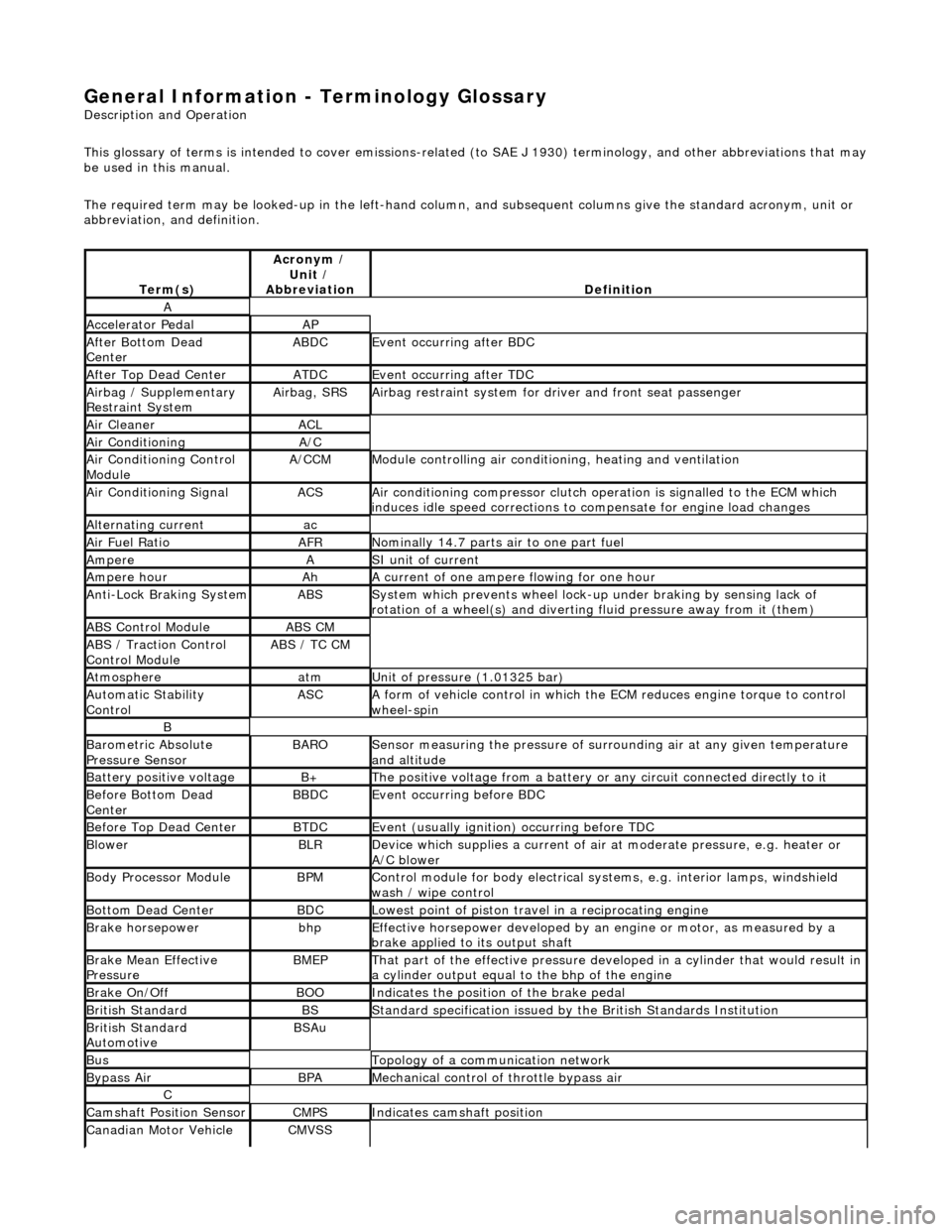
General Information - Terminology Glossary
Description an
d Operation
This glossary of terms is intended to cover emissions-related (to SAE J 1930) term inology, and other abbreviations that may
be used in this manual.
The required term may be looked-up in th e left-hand column, and subsequent columns give the standard acronym, unit or
abbreviation, and definition.
Te rm
(s)
Acr
ony
m /
Unit /
Abbreviation
De fi
nition
A
Accel
e
rator Pedal
AP
Af
ter Botto
m Dead
Center
ABDCEvent occurri ng after
BDC
Af
ter Top Dead CenterATDCEvent occurri ng after
TDC
Ai
rbag /
Supplementary
Restraint System
Airbag, SRSAi rbag restraint system for
dr
iver and front seat passenger
Air Cleane rACL
Air ConditioningA/C
Air Conditioning Con t
rol
Module
A/CCMModule c
ontrolling air conditioning, heating and ventilation
Air Conditioning SignalACSA
i
r conditioning compressor clutch operation is signalled to the ECM which
induces idle speed corrections to co mpensate for engine load changes
Alternating cu
rrent
ac
Ai
r Fuel R
atio
AFRN
omi
nally 14.7 parts air to one part fuel
Ampe
reASI unit of current
Ampere hourAhA current of one ampere
fl
owing for one hour
Anti-Lock Braking SystemABSS
y
stem which prevents wheel lock-up
under braking by sensing lack of
rotation of a wheel(s) and divertin g fluid pressure away from it (them)
ABS Control Mo
dule
ABS CM
ABS /
T
raction Control
Control Module
ABS / T
C CM
Atmosph
e
re
atmU
n
it of pressure (1.01325 bar)
Au
to
matic Stability
Control
ASCA form of vehicle
control
in which the ECM reduces en gine torque to control
wheel-spin
B
Baro me
tric Absolute
Pressure Sensor
BAR OSensor measuring the pressure of surr ou
nding air at any given temperature
and altitude
Bat t
ery positive voltage
B+The posi
ti
ve voltage from a battery or
any circuit connected directly to it
Before Bottom Dead
CenterBBDCEvent occurri ng before BD
C
Before Top Dead
Center
BTD
CEvent (usual ly
ignition) occurring before TDC
Blowe
rBLRDe
vice which supplies a current of air at
moderate pressure, e.g. heater or
A/C blower
Body Processor M
odule
BPMControl modu
le
for body electrical systems, e.g. interior lamps, windshield
wash / wipe control
Bott om D
ead Center
BD
CLowest poin t of piston
travel in a reciprocating engine
Brake hors
epowe
r
bhpEffecti
ve horsepower devel
oped by an
engine or motor, as measured by a
brake applied to its output shaft
Brake Mean Effective
Pres sureBME PThat p
art of the effective
pressure developed in a cyli nder that would result in
a cylinder output equal to the bhp of the engine
Brake On/ O
ff
BOOIn
dic
ates the position of the brake pedal
Br
it
ish Standard
BSStan
dar
d specification issued by the British Standards Institution
Br
it
ish Standard
Automotive
BSAu
BusTopology of a commu n
ication network
Bypass
AirBPAMechanica l
control of throttle bypass air
C
Camshaft Posit
i
on Sensor
CMPSIndi
cat
es camshaft position
Canadian Motor
V
ehicle
CMVSS
Page 529 of 2490
Thi
s sensor uses a piezo-electric sensing element to detect kn
ock which may occur under acceleration at critical conditions.
Should detonation be present the ECM will retard ignition timing of individual cylinders.
Exhaust G
as Recirculation
The EGR
valve (where fitted) reduces NOx
emissions by recirculating a portion of the exhaust gases back into the inlet
manifold.
Heated Oxyg
en Sensors
The h
eated oxygen sensors, one per bank, are situated upstream of the catalysts. Integral
to the sensors are heaters
(under ECM control) which allow the sensor s to reach their operating temperature as soon as possible after engine start. A
comparison between the level of oxygen in the exhaust gas to that in the atmosphere produces an output signal. This signal
is used by the engine closed loop fuel strategy to make fuelling corrections and so control overall emission levels.
Oxygen Sensors
Thes
e sensors, one per bank, are situated downstream of the
catalyst. The comparison of upstream and downstream signals
allows determination of cata lyst conversion efficiency.
Knock Sensor
Page 611 of 2490
E
ngine - Cylinder Head LH
In-ve
hicle Repair
Remova
l
CAU
TION: If a replacement cylinder head is to be installed to a
vehicle with variable camshaft timing (VCT) the cylinder head m ust have the
oil gallery blind rivet removed before installation.
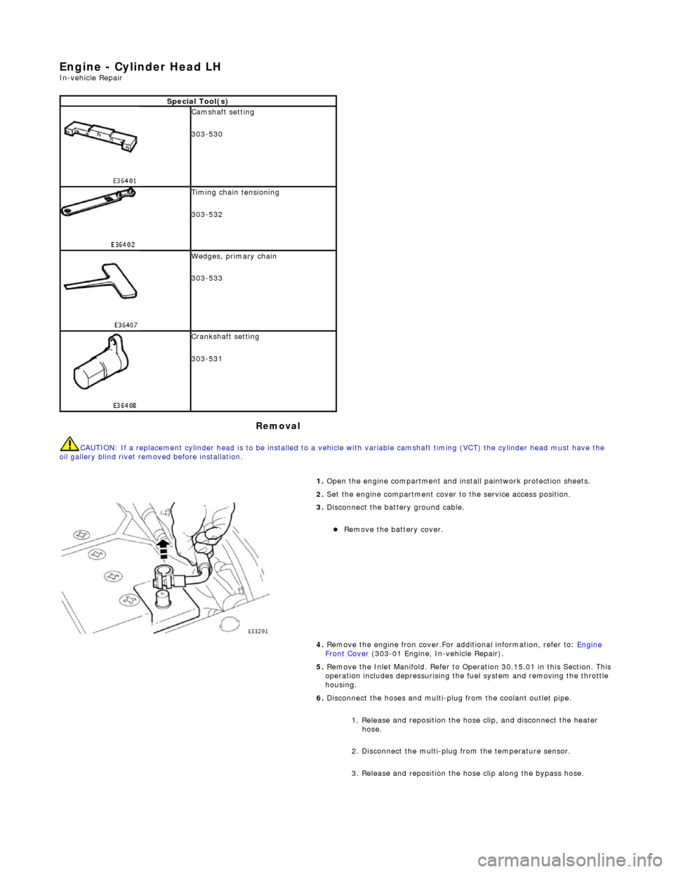
Spe
cial Tool(s)
Cams
haft setting
303-530
Ti
ming chain tensioning
303-532
Wedges, prim
ary chain
303-533
Cr
ankshaft setting
303-531
1.
Open the engine compartment and install paintwork protection sheets.
2. Set the engine compartment cover to the service access position.
3.
Disconnect the battery ground cable.
пЃ¬Re
move the battery cover.
4. Remove the engine fron cover.For additional information, refer to: Engine
Front Cover (303-01 Engi
ne, In-vehicle Repair).
5. Remove the Inlet Manifold. Refer to Operation 30.15.01 in this Section. This operation includes depressurising the fuel system and removing the throttle
housing.
6. Disconnect the hoses and multi-plug from the coolant outlet pipe.
1. Release and reposition the hose clip, and disconnect the heater hose.
2. Disconnect the multi-plug from the temperature sensor.
3. Release and reposition the hose clip along the bypass hose.
Page 625 of 2490
d
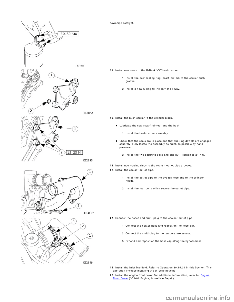
ownpipe catalyst.
39
.
Install new seals to the B-Bank VVT bush carrier.
1. Install the new sealing ring (scarf jointed) to the carrier bush groove.
2. Install a new O-ring to the carrier oil-way.
40
.
Install the bush carrier to the cylinder block.
пЃ¬Lu
bricate the seal (scarf
jointed) and the bush.
1. Install the bush carrier assembly.
пЃ¬Chec
k that the seals are
in place and that the ri ng dowels are engaged
squarely. Fully locate the assembly as much as possible by hand
pressure.
2. Install the two securing bolts and one nut. Tighten to 21 Nm.
41. Install new sealing rings to the coolant outlet pipe grooves.
42
.
Install the coolant outlet pipe.
1. Install the outlet pipe to the bypass hose and to the cylinder heads.
2. Install the four bolts which secure the outlet pipe.
43
.
Connect the hoses and multi-plug to the coolant outlet pipe.
1. Connect the heater hose and reposition the hose clip.
2. Connect the multi-plug to the temperature sensor.
3. Expand and reposition the hose clip along the bypass hose.
44. Install the Inlet Manifold. Refer to Operation 30.15.01 in this Section. This
operation includes installing the throttle housing.
45. Install the engine front cover.For additional information, refer to: Engine
Front Cover (303-01 Engi
ne, In-vehicle Repair).
Page 627 of 2490
E
ngine - Cylinder Head RH
In-ve
hicle Repair
Remova
l
CAU
TION: If a replacement cylinder head is to be installed to a
vehicle with variable camshaft timing (VCT) the cylinder head m ust have the
oil gallery blind rivet removed before installation.
Spe
cial Tool(s)
Cams
haft setting
303-530
Ti
ming chain tensioning
303-532
Wedges, prim
ary chain
303-533
Cr
ankshaft setting
303-531
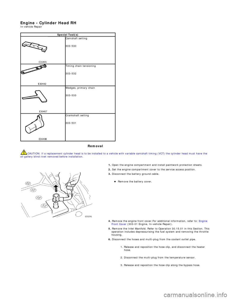
1.
Open the engine compartment and install paintwork protection sheets.
2. Set the engine compartment cover to the service access position.
3.
Disconnect the battery ground cable.
пЃ¬Re
move the battery cover.
4. Remove the engine front cover.For additional information, refer to: Engine
Front Cover (303-01 Engi
ne, In-vehicle Repair).
5. Remove the Inlet Manifold. Refer to Operation 30.15.01 in this Section. This operation includes depressurising the fuel system and removing the throttle
housing.
6. Disconnect the hoses and multi-plug from the coolant outlet pipe.
1. Release and reposition the hose clip, and disconnect the heater hose.
2. Disconnect the multi-plug from the temperature sensor.
3. Release and reposition the hose clip along the bypass hose.
Page 640 of 2490
2. In
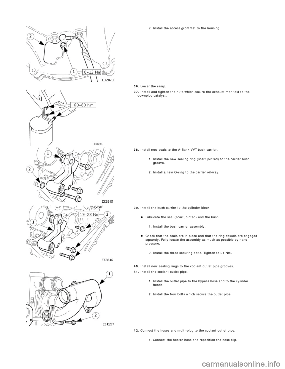
stall the access grommet to the housing.
36. Lower the ramp.
37. Ins
tall and tighten the nuts which secure the exhaust manifold to the
downpipe catalyst.
38 . In
stall new seals to the A-Bank VVT bush carrier.
1. Install the new sealing ring (scarf jointed) to the carrier bush groove.
2. Install a new O-ring to the carrier oil-way.
39 . Install the bush c
arrier to the cylinder block.
пЃ¬Lu
br
icate the seal (scarf
jointed) and the bush.
1. Install the bush carrier assembly.
пЃ¬Chec k that
the seals are
in place and that the ri ng dowels are engaged
squarely. Fully locate the assembly as much as possible by hand
pressure.
2. Install the three securing bolts. Tighten to 21 Nm.
40. Install new sealing rings to the coolant outlet pipe grooves.
41. Install the coolant
outlet pipe.
1. Install the outlet pipe to the bypass hose and to the cylinder heads.
2. Install the four bolts which secure the outlet pipe.
42. Connect the hoses and multi-plug to the coolant outlet pipe.
1. Connect the heater hose and reposition the hose clip.
Page 907 of 2490

56. Disconnect the fuel feed and return hoses.
1. Disconnect the fuel hoses at the Quick Fit connectors,
using special tool 310 - 044 for the feed hose and
310 - 54 for the return hose.
пЃ¬Disconnect the return hose from the feed hose clip.
пЃ¬Fit blanking plugs to the pipes.
57. Disconnect the pipes from the purge valve.
1. Remove the clip which secu res the part load breather
hose to the purge valve.
2. Disconnect the part load breather hose.
3. Disconnect the vacuum hose from the purge valve and reposition the hose.
58. Disconnect the throttle cable.
1. Secure the cable abutment to the bracket with tape or a ratchet strap, if nece ssary (to save subsequent
adjustment procedure). Remove the bolts which
secure the abutment bracke t to the throttle body.
2. Rotate the butterfly actuator cam and disconnect the cable. Reposition the cable.
59. Disconnect the heater and brake servo hoses.
1. Disconnect the he ater return hose.
2. Release the heater feed hose locking lever and
disconnect the hose.