reset JAGUAR X308 1998 2.G User Guide
[x] Cancel search | Manufacturer: JAGUAR, Model Year: 1998, Model line: X308, Model: JAGUAR X308 1998 2.GPages: 2490, PDF Size: 69.81 MB
Page 728 of 2490
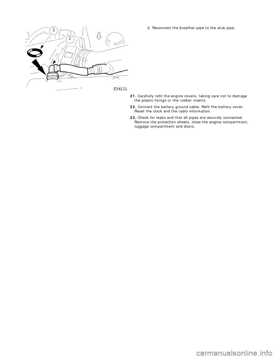
2. Reconnect the breather pipe to the stub pipe.
21. Carefully refit the engine covers, taking care not to damage
the plastic fixings or the rubber inserts.
22. Connect the battery ground cabl e. Refit the battery cover.
Reset the clock and the radio information.
23. Check for leaks and that all pi pes are securely connected.
Remove the protection sheets, close the engine compartment,
luggage compartment and doors.
Page 969 of 2490
Engine Cooling - Cooling Fan Motor and Shroud
Re
moval and Installation
Remov
al
Installation
1.
Di
sconnect the batt
ery ground cable.
R
emove the battery cover.
2. Open the engine compartment and fit paintwork protection
sheets.
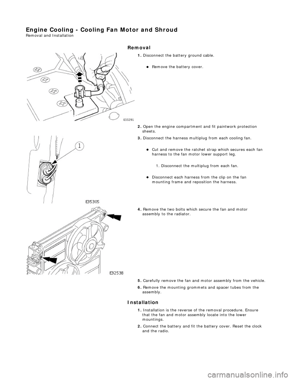
3. Disc
onnect the harness multip
lug from each cooling fan.
Cut an
d remove the ratchet st
rap which secures each fan
harness to the fan moto r lower support leg.
1. Disconnect the mult iplug from each fan.
Di
sconnect each harness
from the clip on the fan
mounting frame and repo sition the harness.
4. R
emove the two bolts which
secure the fan and motor
assembly to the radiator.
5. Carefully remove the fan and mo tor assembly from the vehicle.
6. Re
move the mounting grommets
and spacer tubes from the
assembly.
1. Installation is the reverse of the remova l procedure. Ensure
that the fan and motor assembly locate into the lower
mountings.
2. Connect the battery and fit the battery cover. Reset the clock
and the radio.
Page 979 of 2490

16
.
Refill the cooling system. Refer to the Refill procedure in
General Procedures.
17. Repressurise the climate cont rol system. Refer to Section
412-03 Observe all safety warnin gs and precautions stated in
that section.
18. Close the engine compartment cover.
19. Connect the battery and fit the battery cover. Reset the clock
and the radio.
Page 986 of 2490

16
. Re
fill the cooling system. Refer to the Refill procedure in
General Procedures.
17. Repressurise the climate cont rol system. Refer to Section
412-03 Observe all safety warnin gs and precautions stated in
that section.
18. Close the engine compartment cover.
19. Connect the battery and fit the battery cover. Reset the clock
and the radio.
Page 1046 of 2490
8. Wh ere appropri
ate check kick
down setting is within
specification and reset if requ ired as detailed from step 6
(Installation).
PDU use
rs see 44.15.38
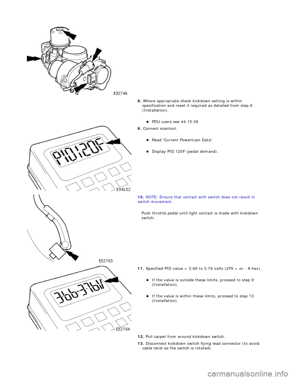
9. Conne ct
scantool.
R
e
ad 'Current Powertrain Data'.
D
i
splay PID 120F (pedal demand).
10 . NO
TE: Ensure that contact with switch does not result in
switch movement.
Push throttle pedal until light contact is made with kickdown
switch.
11. Spe
cified PID value = 3.66 to 3.76 volts (2F9 + or - A hex).
If
the value is outside these limits, proceed to step 9
(Installation).
If t he
value is within these limits, proceed to step 13
(Installation).
12. Pull carpet from around kickdown switch.
13. Disconnect kickdown switch flying lead connector (to avoid
cable twist as the switch is rotated).
Page 1110 of 2490
2.2. Cruise
3. 3. Mechanica l
guard
4. 4. Fixed idle
5. 5. Redundancy
6. 6. Full authority
7. 7. Engine shut-down
Normal mode occurs when the EC M uses the mechanical and monitoring arrangem ent of the throttle valve to control throttle
opening. The ECM does not permit driver demand to be exceeded but it can be restricted to allow for such features as
stability / traction control, or engine power limitation.
The ECM determines engine idle speed by controlling the throttle valve motor to vary the blade angle between the non-
adjustable preset limits of the mechanic al guard and the throttle valve motor.
Cruise mode is engaged as a result of the ECM calculating and controlling the required throttle valve opening via the
vacuum system. When the driver releases the throttle pedal, the input shaft disengages from the mechanical guard or the
vacuum actuator pulls the guard away from th e throttle valve. The throttle pedal will feel light should it be pushed again to
accelerate (pressing the pedal further will re-engage the input shaft with the mechanical guard and restore normal feel).
The ECM utilizes sensors to monitor the relative positions of the mechanical guard and throttle valve and adjusts them to
maintain the set cruise speed.
Mechanical guard mode permits full mechanical operation of the throttle if the ECM detects that a problem has been
encountered with the throttle valve position sensor, dc motor, associated harnesses / connecto rs or the ECM.
Fixed idle mode occurs when any two of the three sensors (two input shaft sensors and the mechanical guard sensor) fail.
The ECM will assume values which represent a blade angl e of approximately 2,5° and 1200 rpm (unloaded) maximum
engine speed.
Redundancy mode occurs when any one of the three sensors (two input shaft sensors and the mechanical guard sensor)
fails. The operational pair will be deemed to be safe to co ntinue without intervention, but cruise will be inhibited.
Full authority mode is invoked when a mech anical guard failure occurs which indicates that the guard is stuck fully open.
The red warning lamp will be lit and road speed will be li mited to 120 kph.
Engine shut-down mode will occur followin g multiple failures, such as mechanical guard mode following full authority mode
(or vice versa) or the throttle blade sticks.
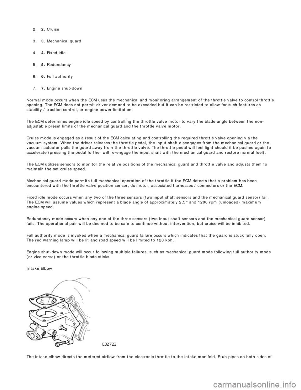
Intake Elbow
The intake elbow directs the metered airflow from the electronic throttle to the intake manifold. Stub pipes on both sides of
Page 1149 of 2490
The E
VAP canister purge valve controls th
e flow rate of fuel vapour drawn into the engine during the canister purge
operation. The valve is opened by a vacu um feed from the induction elbow : the vacu um feed is controlled by the integral
valve solenoid and is applied when the so lenoid is energised. The solenoid is pulsed on (energised) and off by a fixed
frequency (100Hz) variable pulse width control signal (pulse width modulation). By varying the pulse on to off time, the
ECM controls the duty cycle of the valve (time that the valve is open to time closed) and thus the vapour flow rate to the
engine.
With no ECM signal applied to the va lve solenoid, the valve remains closed.
Can
ister Purge Operation
The
following pre-conditions are ne
cessary for purging to commence :
aft
er battery disconnection/reconnection, engine
management adaptations must be re-instated.
engine has run for
at least 8 seconds.
engi
ne coolant temperature is not less than 70 °C.
engine
not running in the fuel
cut off condition (eg overrun).
t
he adaptive fuel correction
function has not registered a rich or lean failure
t
he evaporative emission leak test has not failed
no faults have been diagnosted in th
e rel
evant sensor and valve circuits -
Air Flow Meter (AFM), Engine Coolant
Temperature sensor, Evaporativ e Canister Purge valve and Canister Close Valve (CCV).
If these conditions have been satisfied, purging is started. If any failures are registered, purging is inhibited.
The canister(s) is purged during each driv e cycle at various rates in accordance with the prevailing engine conditions. The
engine management software st ores a map of engine speed (RPM) against engine load (grams of air inducted / rev). For
any given engine speed and load, a vapour purge rate is assigned (purge rate increases with engine speed and load).
The preset purge rates are base d on the assumption of a vapour concentratio n of 100%. The actual amount of vapour is
measured by the closed loop fueling system : the input of evaporative fuel into the engine causes the outputs from the
upstream oxygen sensors to change, the am ount of change providing a measure of the vapour concentration. This feedback
causes the original purge rate to be adju sted and also reduces the amount of fuel input via the injectors to maintain the
correct air to fuel ratio.
Engine speed/load mapping and the corresp onding purge rates are different for single canister, running loss and ORVR
evaporative systems.
Page 1241 of 2490
E
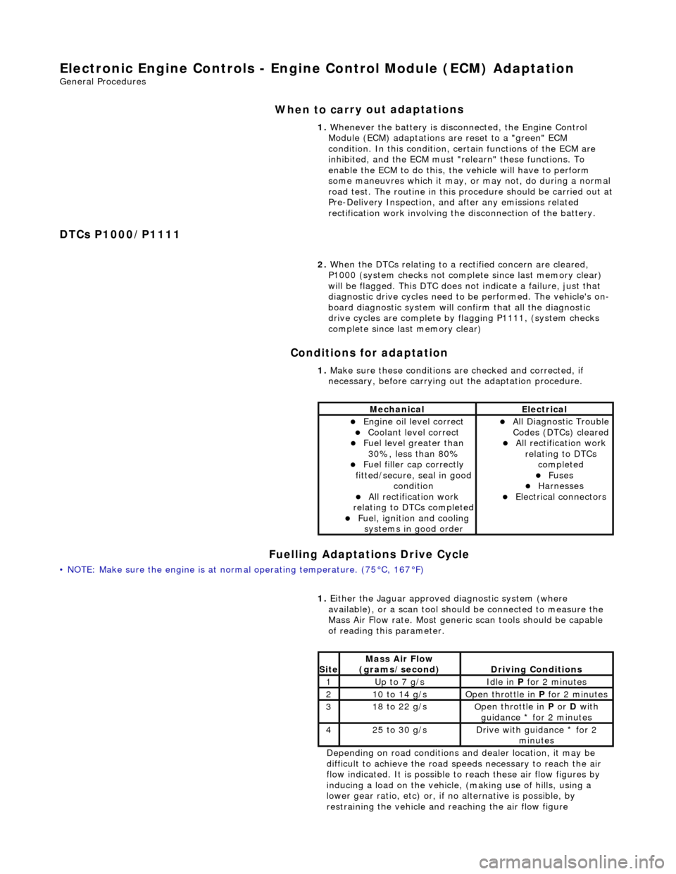
lectronic Engine Controls - Engine
Control Module (ECM) Adaptation
Gen
eral Procedures
When to car
ry out adaptations
DTCs P1000/P1111 Conditions for adaptation
Fuelling Adaptations Drive Cycle
•
NOTE: Make sure the engine is at normal operating
temperature. (75°C, 167°F) 1.
Whenever the battery is disconnected, the Engine Control
Module (ECM) adaptations are reset to a "green" ECM
condition. In this condition, certain functions of the ECM are
inhibited, and the ECM must "r elearn" these functions. To
enable the ECM to do this, the vehicle will have to perform
some maneuvres which it may, or may not, do during a normal
road test. The routine in this pr ocedure should be carried out at
Pre-Delivery Inspection, and after any emissions related
rectification work involving the disconnection of the battery.
2. When the DTCs relating to a rectified concern are cleared,
P1000 (system checks not complete since last memory clear)
will be flagged. This DTC does no t indicate a failure, just that
diagnostic drive cycles need to be performed. The vehicle's on-
board diagnostic system will confirm that all the diagnostic
drive cycles are complete by flagging P1111, (system checks
complete since last memory clear)
1. Make sure these conditions are checked and corrected, if
necessary, before carrying ou t the adaptation procedure.
MechanicalElectrical
Engi
ne oil level correct
Coo
lant level correct
F
uel level greater than
30%, less than 80%
F
uel filler cap correctly
fitted/secure, seal in good condition
Al
l rectification work
relating to DTCs completed
F
uel, ignition and cooling
systems in good order
Al
l Diagnostic Trouble
Codes (DTCs) cleared
Al
l rectification work
relating to DTCs completed
F
uses
Harnes
ses
E
lectrical connectors
1.
Either
the Jaguar approved diagnostic system (where
available), or a scan tool should be connected to measure the
Mass Air Flow rate. Most generi c scan tools should be capable
of reading this parameter.
Depending on road conditions and dealer location, it may be
difficult to achieve the road sp eeds necessary to reach the air
flow indicated. It is possible to reach these air flow figures by
inducing a load on the vehicle, (making use of hills, using a
lower gear ratio, etc) or, if no alternative is possible, by
restraining the vehicle and re aching the air flow figure
Si
te
Mass Air Flow
(gra
ms/second)
D
riving Conditions
1Up t
o 7 g/s
Idle
in
P for 2 minutes
21
0 to 14 g/s
O
pen throttle in
P for 2 minutes
31
8 to 22 g/s
O
pen throttle in
P or D with
guidance * for 2 minutes
42
5 to 30 g/s
D
rive with guidance * for 2
minutes
Page 1341 of 2490

3. NOTE: Ensure extreme clea nliness and never reuse
transmission fluid.
Using a new gasket, install the fl uid pan and tighten the fixings
to the specified torque figure.
4. Connect the battery and fit the battery cover..
Reset the radio and the clock.
5. Refer to (44.24.02) for fluid fill procedure.
Page 1351 of 2490
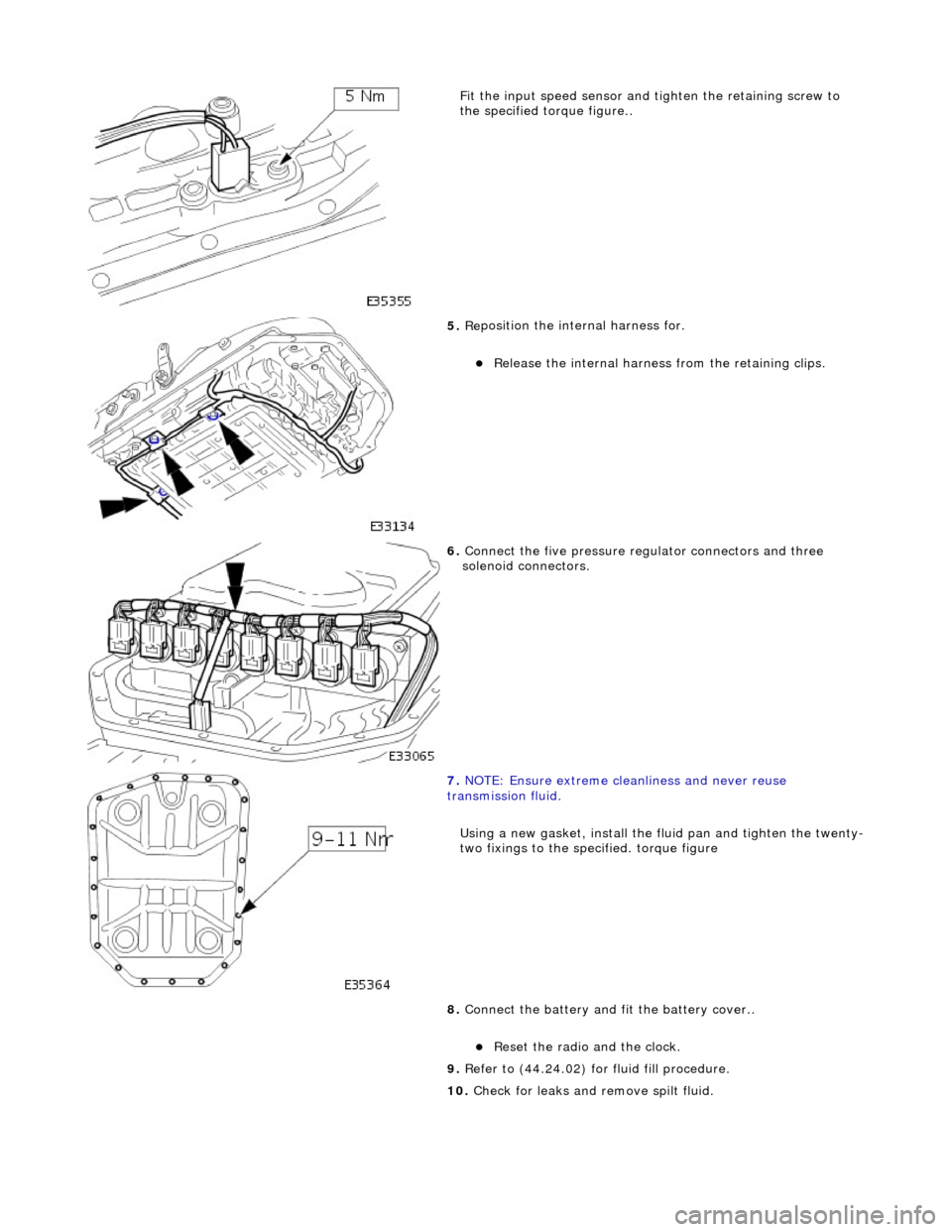
Fit the inpu
t speed sensor and
tighten the retaining screw to
the specified to rque figure..
5. Re
position the inte
rnal harness for.
R
elease the internal harness
from the retaining clips.
6. Connect
the five pressure re
gulator connectors and three
solenoid connectors.
7. N
OTE: Ensure extreme clea
nliness and never reuse
transmission fluid.
Using a new gasket, install the fl uid pan and tighten the twenty-
two fixings to the specified. torque figure
8. Connect the battery and fit the battery cover..
Reset th
e radio and the clock.
9. Refer to (44.24.02) for fluid fill procedure.
10. Check for leaks and remove spilt fluid.