windshield wipers JAGUAR X308 1998 2.G Workshop Manual
[x] Cancel search | Manufacturer: JAGUAR, Model Year: 1998, Model line: X308, Model: JAGUAR X308 1998 2.GPages: 2490, PDF Size: 69.81 MB
Page 32 of 2490

Rear Cup Holder (76.25.27)
Steering Col u
mn
Lower Shroud (76.46.03)
Steering Column Upper Shroud (76.46.02)
501‐14: Handles, Locks, Latches and Entry Systems
Description and Operation
Handles, Locks, Latches and Entry Systems
Removal and Installation
Exterior Driver Door Handle (76.58.07)
Driver Door Latch (76.37.74)
Glove Compartment Lid Ha
ndle (76.52.08)
Glove Compartment Lid Lock Cylinder (76.52.23)
Luggage Compartment Lid Latch (76.19.25)
Luggage Compartment Lid Latch Actuator (76.19.25)
Luggage Compartment Lid Release Switch (86.25.56)
Luggage Compartment Lid Warning Indicator Switch (86.65.93)
Exterior Passenger Door Handle (76.58.08)
Passenger Door Latch (76.37.75)
Exterior Rear Door Handle (76.58.02)
Rear Door Latch (76.37.09)
501‐16: Wipers and Washers
Descriptio
n and Operation
Wipers and Washers
Removal and Installation
Headlamp Washer Jet (84.20.08)
Headlamp Washer Pump (84.20.21)
Rain Sensor (84.12.10) (86.56.62)
Windshield Washer Pump (84.10.21)
Windshield Washer Reservoir (84.10.01) (84.10.03)
Windshield Wiper Motor (84.15.13)
Windshield Wiper/
Washer Switch (86.65.42)
Wiper Pivot Arm (84.15.03)
Page 2212 of 2490
Glass, Frames and Mechanisms - Windshield Glass
Removal and Installation
Removal
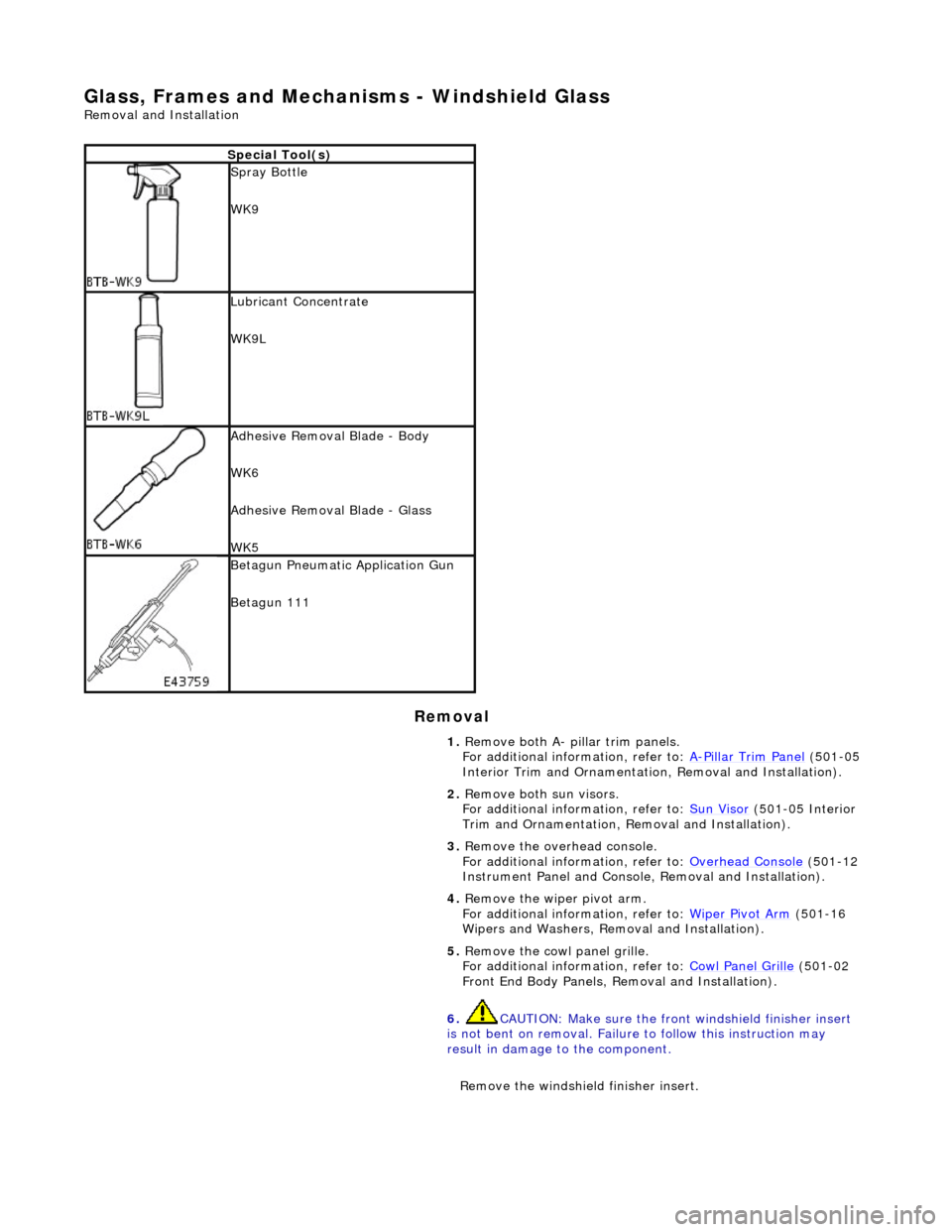
Special Tool(s)
Spray Bottle
WK9
Lubricant Concentrate
WK9L
Adhesive Removal Blade - Body
WK6
Adhesive Removal Blade - Glass
WK5
Betagun Pneumatic Application Gun
Betagun 111
1. Remove both A- pill ar trim panels.
For additional information, refer to: A
-Pillar Trim Panel (501-05
Interior Trim and Ornamentatio n, Removal and Installation).
2. Remove both sun visors.
For additional information, refer to: Sun Visor
(501-05 Interior
Trim and Ornamentation, Re moval and Installation).
3. Remove the overhead console.
For additional information, refer to: Overhead Console
(501-12
Instrument Panel and Console, Removal and Installation).
4. Remove the wiper pivot arm.
For additional information, refer to: Wiper Pivot Arm
(501-16
Wipers and Washers, Remo val and Installation).
5. Remove the cowl panel grille.
For additional information, refer to: Cowl Panel Grille
(501-02
Front End Body Panels, Removal and Installation).
6. CAUTION: Make sure the front windshield finisher insert
is not bent on removal. Failure to follow this instruction may
result in damage to the component.
Remove the windshield finisher insert.
Page 2217 of 2490
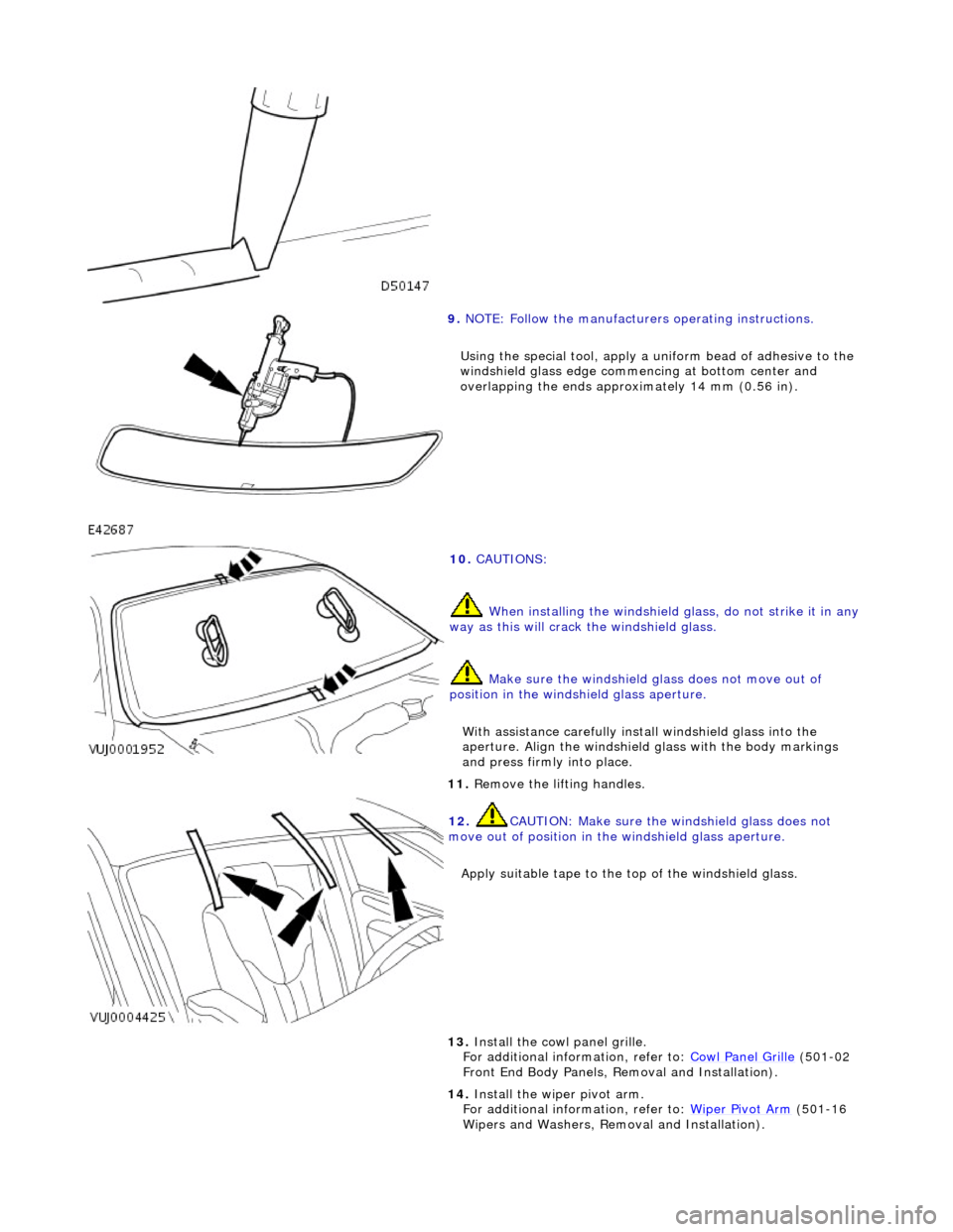
9. NOTE: Follow the manufacturers operating instructions.
Using the special tool, apply a uni form bead of adhesive to the
windshield glass edge commenc ing at bottom center and
overlapping the ends approximately 14 mm (0.56 in).
10. CAUTIONS:
When installing the windshield glass, do not strike it in any
way as this will crack the windshield glass.
Make sure the windshield glass does not move out of
position in the windshield glass aperture.
With assistance carefully install windshield glass into the
aperture. Align the windshield glass with the body markings
and press firmly into place.
11. Remove the lifting handles.
12. CAUTION: Make sure the windshield glass does not
move out of position in the windshield glass aperture.
Apply suitable tape to the to p of the windshield glass.
13. Install the cowl panel grille.
For additional information, refer to: Cowl Panel Grille (501-02
Front End Body Panels, Removal and Installation).
14. Install the wiper pivot arm.
For additional information, refer to: Wiper Pivot Arm
(501-16
Wipers and Washers, Remo val and Installation).
Page 2306 of 2490
Wipers and Washers - Wipers and Washers
Description and Operation
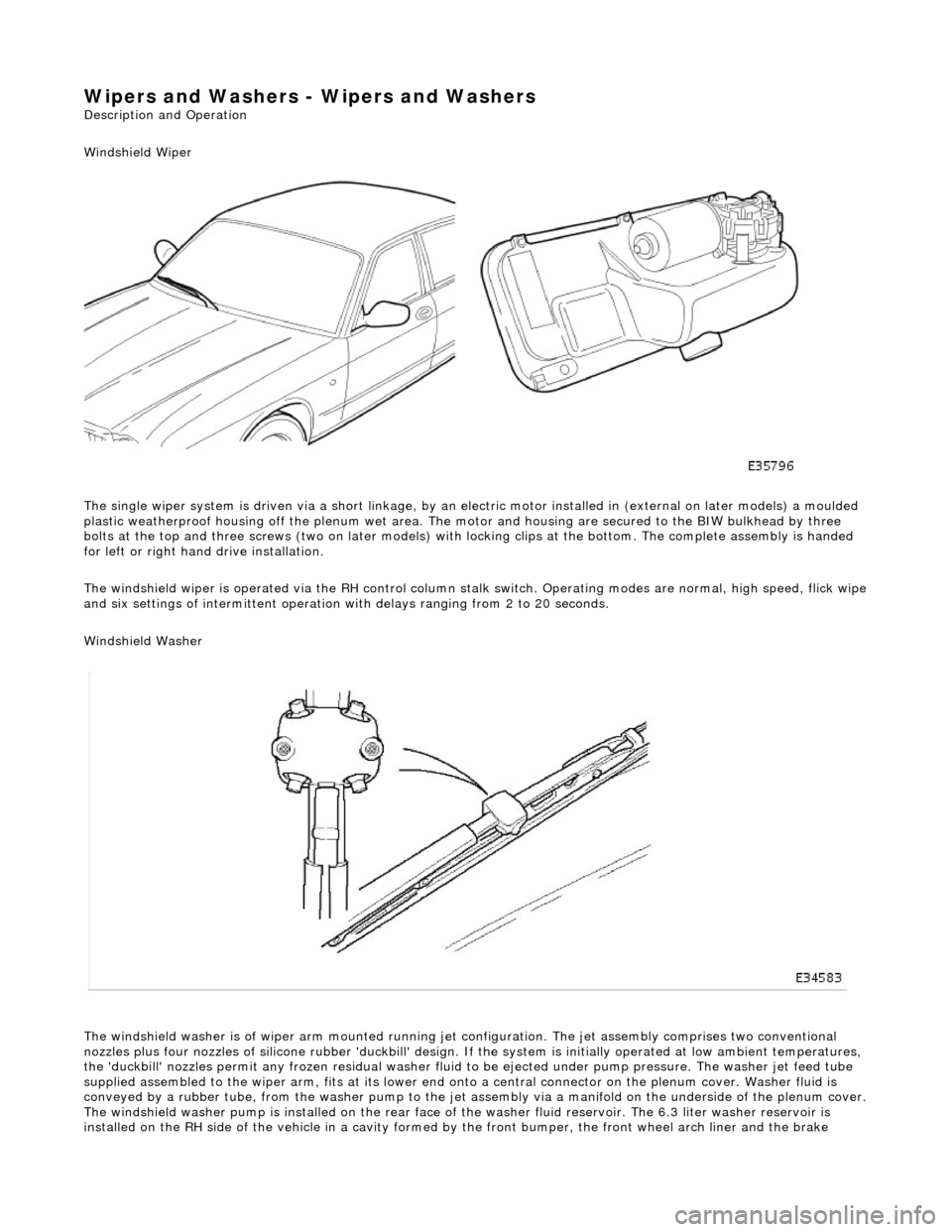
Windshield Wiper
The single wiper system is driven via a sh ort linkage, by an electric motor installed in (external on later models) a moulded
plastic weatherproof housing o ff the plenum wet area. The motor and housing are secured to the BIW bulkhead by three
bolts at the top and three screws (two on later models) with locking clips at the bottom. The complete assembly is handed
for left or right hand drive installation.
The windshield wiper is operated via the RH control column stalk switch. Operating modes are normal, high speed, flick wipe
and six settings of intermittent operation with delays ranging from 2 to 20 seconds.
Windshield Washer
The windshield washer is of wiper arm mounted running jet configuration. The je t assembly comprises two conventional
nozzles plus four nozzles of silicone rubbe r 'duckbill' design. If the system is initially operated at low ambient temperatures ,
the 'duckbill' nozzles permit an y frozen residual washer fluid to be ejected un der pump pressure. The washer jet feed tube
supplied assembled to the wiper ar m, fits at its lower end onto a central connector on the pl enum cover. Washer fluid is
conveyed by a rubber tube, from the washer pump to the jet assembly via a manifold on the underside of the plenum cover.
The windshield washer pump is installed on the rear face of the washer fluid reservoir. The 6.3 liter washer reservoir is
installed on the RH side of th e vehicle in a cavity formed by the front bu mper, the front wheel arch liner and the brake
Page 2312 of 2490
Wipers and Washers - Rain Sensor
Removal and Installation
Removal
Installation
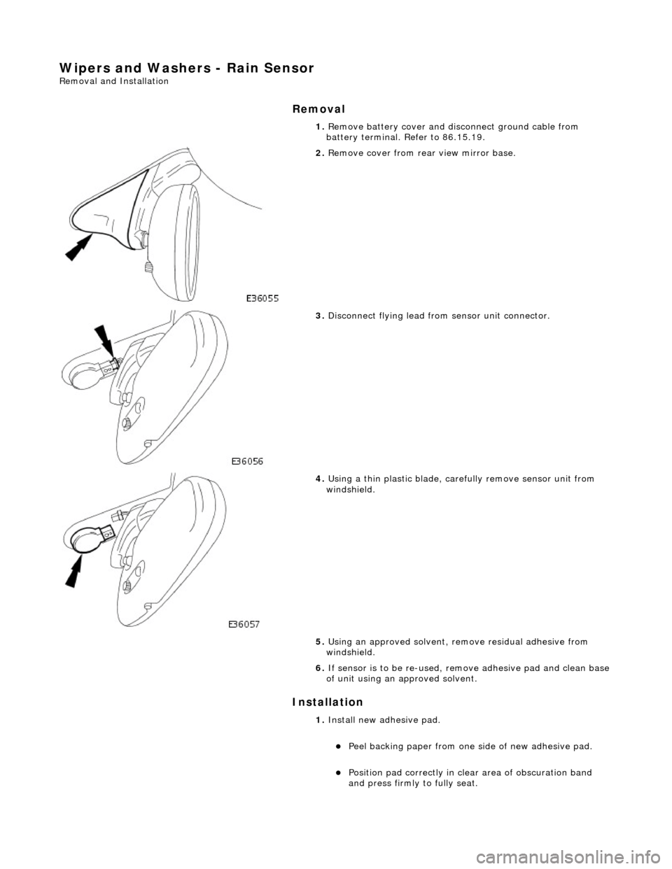
1. Remove battery cover and disc onnect ground cable from
battery terminal. Refer to 86.15.19.
2. Remove cover from rear view mirror base.
3. Disconnect flying lead from sensor unit connector.
4. Using a thin plastic blade, carefully remove sensor unit from
windshield.
5. Using an approved solvent, re move residual adhesive from
windshield.
6. If sensor is to be re-used, remove adhesive pad and clean base
of unit using an approved solvent.
1. Install new ad hesive pad.
Peel backing paper from one si de of new adhesive pad.
Position pad correctly in clear area of obscuration band
and press firmly to fully seat.
Page 2314 of 2490
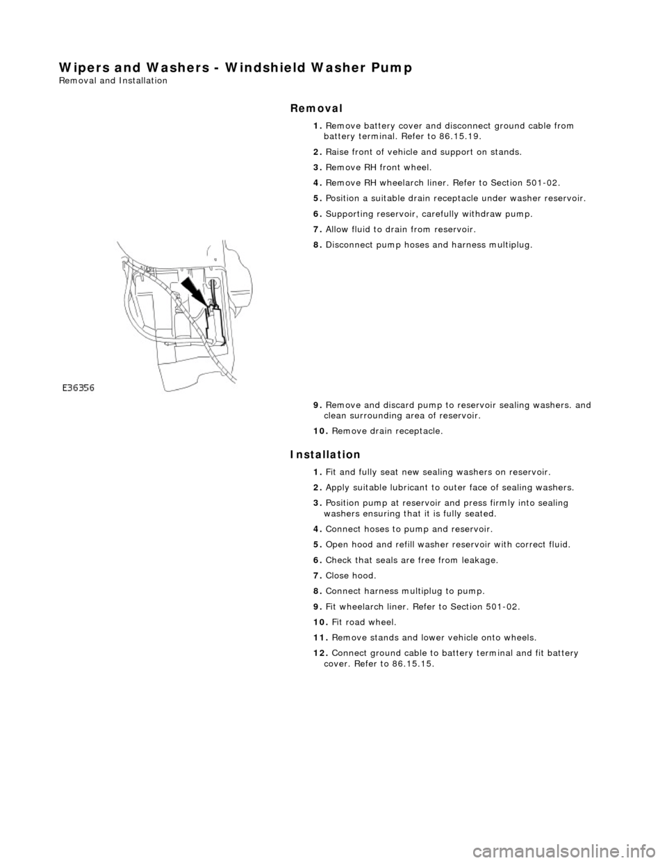
Wipers and Washers - Windshield Washer Pump
Removal and Installation
Removal
Installation
1.
Remove battery cover and disc onnect ground cable from
battery terminal. Refer to 86.15.19.
2. Raise front of vehicle and support on stands.
3. Remove RH front wheel.
4. Remove RH wheelarch liner. Refer to Section 501-02.
5. Position a suitable drain recept acle under washer reservoir.
6. Supporting reservoir, ca refully withdraw pump.
7. Allow fluid to drain from reservoir.
8. Disconnect pump hoses and harness multiplug.
9. Remove and discard pump to re servoir sealing washers. and
clean surrounding area of reservoir.
10. Remove drain receptacle.
1. Fit and fully seat new sealing washers on reservoir.
2. Apply suitable lubricant to outer face of sealing washers.
3. Position pump at reservoir and press firmly into sealing
washers ensuring that it is fully seated.
4. Connect hoses to pump and reservoir.
5. Open hood and refill washer re servoir with correct fluid.
6. Check that seals are free from leakage.
7. Close hood.
8. Connect harness multiplug to pump.
9. Fit wheelarch liner. Refe r to Section 501-02.
10. Fit road wheel.
11. Remove stands and lowe r vehicle onto wheels.
12. Connect ground cable to batt ery terminal and fit battery
cover. Refer to 86.15.15.
Page 2315 of 2490
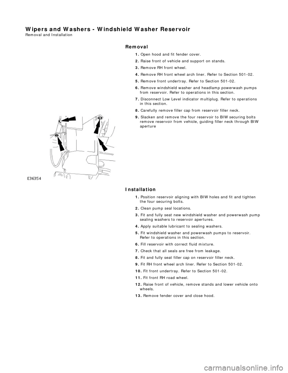
Wipers and Washers - Windshield Washer Reservoir
Removal and Installation
Removal
Installation
1.
Open hood and fit fender cover.
2. Raise front of vehicle and support on stands.
3. Remove RH front wheel.
4. Remove RH front wheel arch li ner. Refer to Section 501-02.
5. Remove front undertray. Refer to Section 501-02.
6. Remove windshield washer and headlamp powerwash pumps
from reservoir. Refer to op erations in this section.
7. Disconnect Low Level indicator mu ltiplug. Refer to operations
in this section.
8. Carefully remove filler cap from reservoir filler neck.
9. Slacken and remove the four re servoir to BIW securing bolts
remove reservoir from vehicle, guiding filler neck through BIW
aperture
1. Position reservoir aligning with BIW holes and fit and tighten
the four securing bolts.
2. Clean pump seal locations.
3. Fit and fully seat new windshie ld washer and powerwash pump
sealing washers to reservoir apertures.
4. Apply suitable lubricant to sealing washers.
5. Fit windshield washer and powerwash pumps to reservoir.
Refer to operations in this section.
6. Fill reservoir with correct fluid mixture.
7. Check that all seals are free from leakage.
8. Fit and fully seat filler cap on reservoir filler neck.
9. Fit RH front wheel arch liner. Refer to Section 501-02.
10. Fit front undertray. Refer to Section 501-02.
11. Fit front RH road wheel.
12. Raise front of vehicle, remove stands and lower vehicle onto
wheels.
13. Remove fender cover and close hood.
Page 2316 of 2490
Wipers and Washers - Windshield Wiper MotorVehicles Built Up To:
10/1997
Removal and Installation
Removal
1. Remove battery cover and disc onnect ground cable from
battery terminal. Refer to 86.15.19.
2. Remove top covers from LH an d RH bulkheads and rear of
engine compartment. Refer to 76.11.33 and 76.11.35.
3. Remove wiper arm and blade as sembly. Refer to 84.15.44.90.
4. Remove plenum cover. Refer to 76.10.01
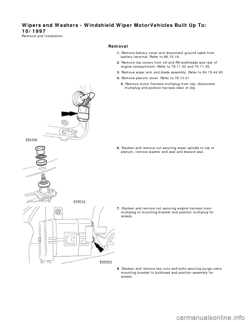
5. Remove motor harness multiplug from clip, disconnect
multiplug and position harness clear of clip.
6. Slacken and remove nut securi ng wiper spindle to top of
plenum, remove washer and seal and discard seal.
7. Slacken and remove nut securing engine harness main
multiplug to mounting bracke t and position multiplug for
access.
8. Slacken and remove two nuts an d bolts securing purge valve
mounting bracket to bulkhead and position assembly for
access.
Page 2319 of 2490
Wipers and Washers - Windshield Wiper MotorVehicles Built From:
10/1997
Removal and Installation
Removal
1. Remove battery cover and disc onnect ground cable from
battery terminal. Refer to 86.15.19.
2. Remove top covers from LH an d RH bulkheads and rear of
engine compartment. Refer to 76.11.33 and 76.11.35.
3. Remove wiper arm and blade as sembly. Refer to 84.15.44.90.
4. Remove plenum cover. Refer to 76.10.01
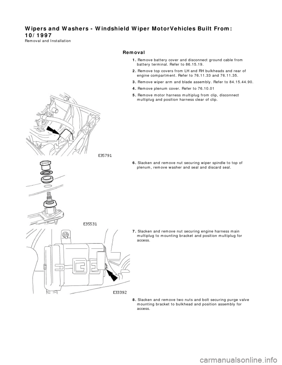
5. Remove motor harness multiplug from clip, disconnect
multiplug and position harness clear of clip.
6. Slacken and remove nut securi ng wiper spindle to top of
plenum, remove washer and seal and discard seal.
7. Slacken and remove nut securing engine harness main
multiplug to mounting bracke t and position multiplug for
access.
8. Slacken and remove two nuts an d bolt securing purge valve
mounting bracket to bulkhead and position assembly for
access.
Page 2322 of 2490
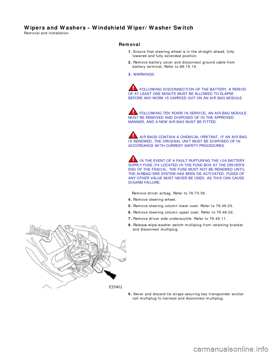
Wipers and Washers - Windshield Wiper/Washer Switch
Removal and Installation
Removal
1. Ensure that steering wheel is in the straight ahead, fully
lowered and fully ex tended position.
2. Remove battery cover and disc onnect ground cable from
battery terminal. Refer to 86.15.19.
3. WARNINGS:
FOLLOWING DISCONNECTION OF THE BATTERY, A PERIOD
OF AT LEAST ONE MINUTE MUST BE ALLOWED TO ELAPSE
BEFORE ANY WORK IS CARRIED OUT ON AN AIR BAG MODULE.
FOLLOWING TEN YEARS IN SERVICE, AN AIR BAG MODULE
MUST BE REMOVED AND DISPOSED OF IN THE APPROVED
MANNER, AND A NEW AIR BAG MUST BE FITTED.
AIR BAGS CONTAIN A CHEMICAL IRRITANT. IF AN AIR BAG
IS RENEWED, THE ORIGINAL UNIT MUST BE DISPOSED OF IN
ACCORDANCE WITH CURRENT SAFETY PROCEDURES.
IN THE EVENT OF A FAULT RUPTURING THE 10A BATTERY
SUPPLY FUSE (F4 LOCATED IN THE FUSE-BOX AT THE DRIVER'S
END OF THE FASCIA), THE FUSE MUST NOT BE RENEWED UNTIL
THE AIRBAG/SRS SYSTEM HAS BEEN DE-ACTIVATED. FUSES OF
ANY OTHER VALUE MUST NEVER BE USED, AS THIS CAN CAUSE
DISARM FAILURE.
Remove driver airbag. Refer to 76.73.39.
4. Remove steeri ng wheel.
5. Remove steering column lowe r cowl. Refer to 76.46.03.
6. Remove steering column upper cowl. Refer to 76.46.02.
7. Remove driver side unders cuttle. Refer to 76.46.11.
8. Release wipe/washer switch mult iplug from retaining bracket
and disconnect multiplug.
9. Sever and discard tie straps se curing key transponder exciter
coil multiplug to harness and disconnect multiplug.