weight JAGUAR X308 1998 2.G User Guide
[x] Cancel search | Manufacturer: JAGUAR, Model Year: 1998, Model line: X308, Model: JAGUAR X308 1998 2.GPages: 2490, PDF Size: 69.81 MB
Page 309 of 2490

Brake System - General Inform
ation - Brake System
D
iagnosis and Testing
Principles of Operations
The brake system operates by transferring effort applied to th e brake pedal, by the driver to the brakes at each wheel.
The braking effort is distributed to each wheel, using a hydraulic system. The system is assisted using a vacuum brake
booster that reduces pedal effort for a given hydraulic pressure. The parking brake operates on the rear wheels and is
applied using a hand operated control.
I
nspection and Verification
•
NOTE: Prior to carrying out any diagno
sis, make sure that the brake system warning indicator is functional.
Visually examine the front and rear tire and wheel assemblies for damage such as un even wear patterns, tread worn out or
sidewall damage. Verify the tires are th e same size, type and, where possible, same manufacture. Replace the damaged
wheel or excessively worn tire. For a dditional information, refer toSection 204
-0
4 Wheels and Tires
.
W
heels and tires must be cleared of an
y foreign matter and tire pressures ad justed to the correct specification.
If the tires exhibit uneven wear or feathering, the cause must be corrected. Check the steering and suspension components
for damage or wear and, if ne cessary, check and adjust front wheel alignment. For additional information, refer toSection
204
-00 Suspen
sion System
- General Informati
on
.
Road Test
V
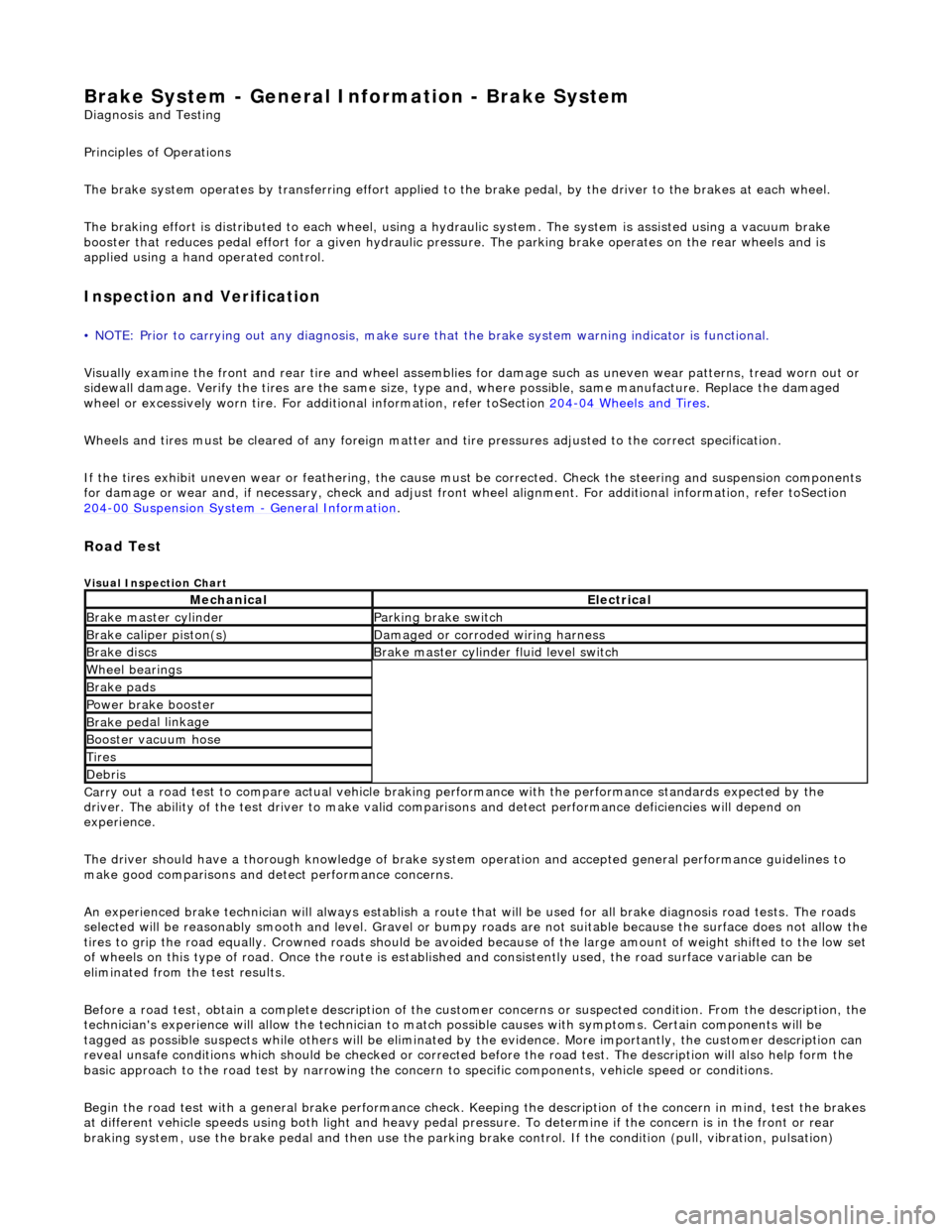
isual Inspection Chart
Carr
y out a road test to compare actual vehicle braking performance with the
performance standards expected by the
driver. The ability of the test driver to make valid compar isons and detect performance deficiencies will depend on
experience.
The driver should have a thorough knowledge of brake system operation and accepted general performance guidelines to
make good comparisons and de tect performance concerns.
An experienced brake technician will always establish a route that will be used for all br ake diagnosis road tests. The roads
selected will be reasonably smooth and level. Gravel or bump y roads are not suitable because the surface does not allow the
tires to grip the road equally. Crowned roads should be avoide d because of the large amount of weight shifted to the low set
of wheels on this type of road. Once th e route is established and consistently used, the road surface variable can be
eliminated from the test results.
Before a road test, obtain a complete description of the customer concerns or suspec ted condition. From the description, the
technician's experience will allow the te chnician to match possible causes with symptoms. Certain components will be
tagged as possible suspects while others wi ll be eliminated by the evidence. More importantly, the customer description can
reveal unsafe conditions which should be ch ecked or corrected before the road test. The description will also help form the
basic approach to the road test by narrowing the concern to specific components, vehicle speed or conditions.
Begin the road test with a general brake performance check. Keeping the description of the concern in mind, test the brakes
at different vehicle speeds using both ligh t and heavy pedal pressure. To determine if the concern is in the front or rear
braking system, use the brake pe dal and then use the parking brake control. If the condition (pull, vibration, pulsation)
MechanicalElectrical
Brake m
aster cylinder
Parkin
g brake switch
Brake ca
liper piston(s)
D
amaged or corroded wiring harness
Brake di
scs
B
rake master cylinder fluid level switch
Wh
eel bearin
gs
Brake pads
Power brake booster
Brake ped
al linkage
Boost
er vacuum hose
Tire
s
De
bris
Page 909 of 2490

1. Remove the nut which secures the selector lever to
the transmission cross shaft.
2. Remove the selector cable abutment bolts.
3. Disconnect the selector arm from the cross shaft.
67. Loosen the bolt which secures the engine rear mounting
rubber to the transmission.
68. Position a transmission jack e.g. Epco V100 and raise the
support bed of the jack to take the weight of the transmission.
Fit and adjust the chains to secure the transmission to the jack.
69. Remove the engine rear mounting assembly.
Remove the mounting centre bolt.
Remove the four bolts which secure the crossmember to
the body.
Remove the crossmember and mounting assembly.
70. Release the engine and tran smission assembly from the
engine compartment.
Take the weight of the engine / transmission with the
hoist and move it towards th e front of the vehicle.
Lower the transmission jack slightly to release the
securing chains. Remove the ja ck from below the vehicle.
Page 912 of 2490

Align th
e engine front mountings and fit the securing nuts.
Tighte
n to the stated torque value.
3. Operate the crane controls and the ramp simultaneously (with
assistance) to raise the vehicle to a convenient working height.
4. Po
sition the transmission jack and raise it to take the weight of
the transmission. Fit and adjust the chains to secure the
transmission to the jack.
5. Fit th
e engine rear mounting bracket.
Fi
t the four bolts which secu
re the crossmember to the
body.
Fi t t
he bolt which secures the
engine rear mounting rubber
to the transmission.
6. Tigh ten th
e rear mounting bolts
to the stated torque figure.
7. Release and remove the transmission jack.
8. Operate the crane controls and the ramp simultaneously (with
assistance) to lower the vehicle to a convenient working height.
9. Lower th e cran
e and remove th
e chain assembly and lifting
eyes.
Page 1062 of 2490

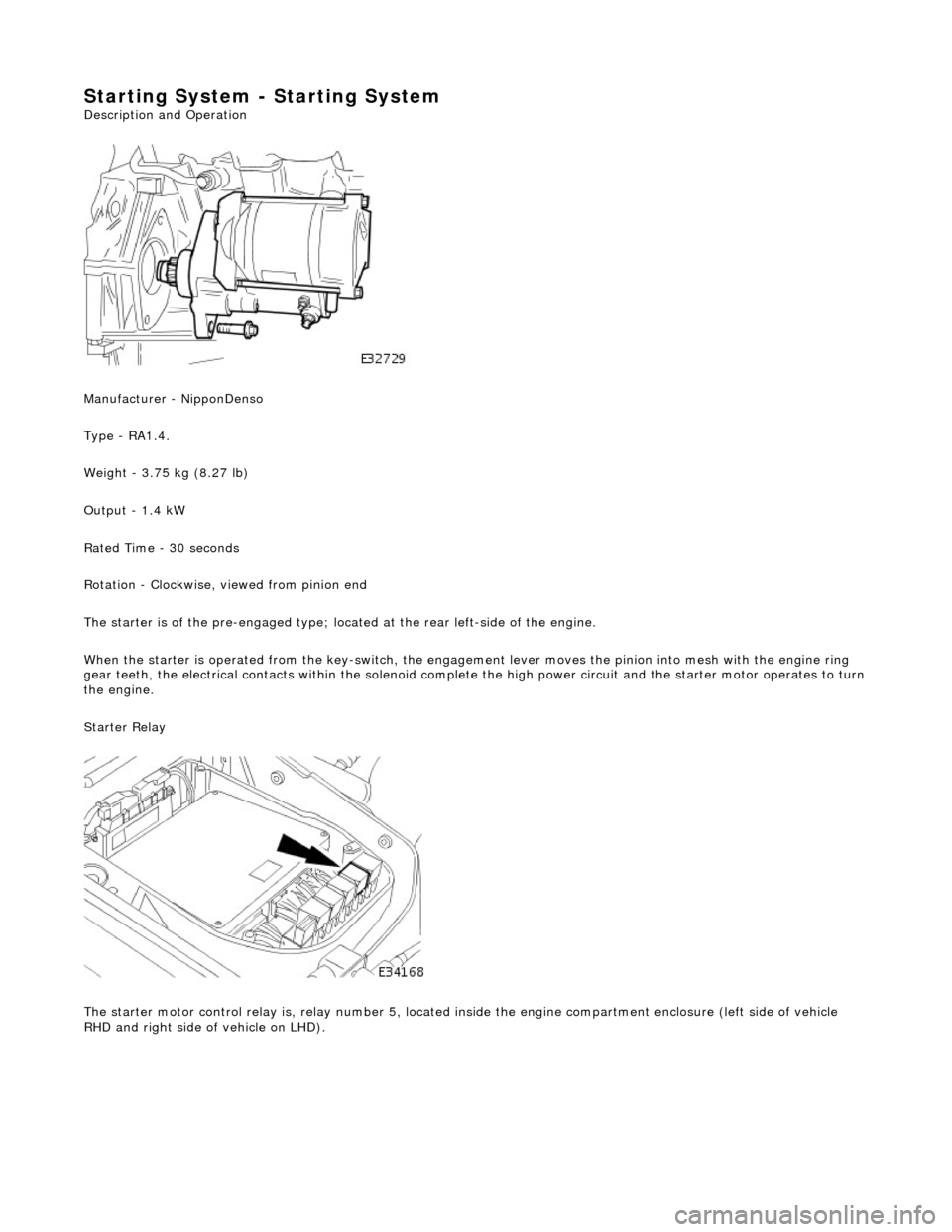
Starting System - Starting System
Description and Operation
Manufacturer - NipponDenso
Type - RA1.4.
Weight - 3.75 kg (8.27 lb)
Output - 1.4 kW
Rated Time - 30 seconds
Rotation - Clockwise, viewed from pinion end
The starter is of the pre-engaged type; loca ted at the rear left-side of the engine.
When the starter is operated from the key-switch, the engagement lever moves the pinion into mesh with the engine ring
gear teeth, the electrical contacts within the solenoid complete the high power circuit and the starter motor operates to turn
the engine.
Starter Relay
The starter motor control relay is, relay nu mber 5, located inside the engine compartment enclosure (left side of vehicle
RHD and right side of vehicle on LHD).
Page 1345 of 2490

Automatic Transmission/Transaxle - 4.0L NA V8 - AJ27/3.2L NA V8 - AJ26
- Extension Housing O-Ring Seal
In-vehicle Repair
Removal
1. Select N position.
2. Raise the vehicle for access.
3. Remove the front muffler, 30.10.18.
4. Locate a transmission jack, Epco V-100 or similar, under the
transmission unit.
Adjust the angle of the jack to suit the transmission.
Secure the side clamps.
Pass the safety chain over the transmission unit and
secure.
Take the weight of the transmission and engine.
5. Remove the engine rear mounting bracket.
1. Remove the engine rear mounting to bracket bolt.
2. Remove the mounting bracket to body bolts.
6. Gently lower the transmission jack.
7. CAUTION: Under no circumstan ces remove the driveshaft
to flexible coupling fixings.
Detach the driveshaft fro m the transmission unit.
Mark the position of the coupling to drive flange.
Remove the three bolts which secure the transmission
drive flange to the flexible coupling .
8. Remove the rear extension housing assembly.
1. Remove the ten bolts, noting their location for installation.
2. Remove and discard the O-ring.
Page 1371 of 2490

Automatic Transmission/Transaxle - 4.0L NA V8 - AJ27/3.2L NA V8 - AJ26
- Transmission Support Insulator
In-vehicle Repair
Removal
Installation
1. Raise the vehicle on a ramp to a suitable height for working on
the rear mounting.
2. Remove the bolt which secure s the engine rear mounting
rubber to the transmission.
3. Position a transmission jack under the transmission casing.
Take the weight of the transmission on the jack.
4. Remove the rear mounting rubber.
1. Slacken the four bolt s which secure the rear
crossmember to the vehicle floor.
2. Remove the two bolts which secure the mounting rubber to the crossmember.
3. Remove the mounting rubber.
1. Fit the mounting rubber assembly to position and tighten the
centre bolt to 30-40 Nm .
2. Tighten the crossmember to body bolts and the mounting
rubber to crossmember bolts to 22-28 Nm.
Page 1376 of 2490

2. Reposition the tank.
8. Install engine lifting bracket 303 - 536 at the rear LH.
9. Support the engine using 303 - 021.
1. Adjust and locate the stan ds in the LH and RH fender
channels and tighten the beam fixings.
2. Engage the support hook s in the lifting brackets.
3. Tighten the support hook adjusters and take the weight of the engine.
10. Raise the vehicle for access.
11. Remove the LH downpipe cata lytic converter (17.50.09).
12. Remove the front muffler (30.10.18).
13. Remove the RH downpipe catalytic converter (17.50.09 and
17.50.10).
14. Drain the transmission fluid, (44.24.02).
15. Locate a transmission jack, Epco V-100 or similar, under the
transmission unit.
Adjust the angle of the jack to suit the transmission.
Secure the side clamps.
Pass the safety chain over the transmission unit and
secure.
Page 1446 of 2490

Automatic Transmission/Transaxle - 4.0L SC V8 - AJ26 - Transmission
Support Insulator
In-vehicle Repair
Removal
Installation
1. Raise the vehicle on a ramp to a suitable height for working on
the rear mounting.
2. Remove the bolt which secure s the engine rear mounting
rubber to the transmission.
3. Position a transmission jack under the transmission casing.
Take the weight of the transmission on the jack.
4. Remove the rear mounting rubber.
1. Slacken the four bolt s which secure the rear
crossmember to the vehicle floor.
2. Remove the two bolts which secure the mounting rubber to the crossmember.
3. Remove the mounting rubber.
1. Fit the mounting rubber assembly to position and tighten the
centre bolt to 30-40 Nm .
2. Tighten the crossmember to body bolts and the mounting
rubber to crossmember bolts to 22-28 Nm.
Page 1450 of 2490

brackets.
3. Tighten the support hook adjusters to take the weight of the engine.
12. Raise the vehicle for access.
13. Remove the LH downpipe catalytic converter. Refer to
Operation 17.50.09.
14. Remove the front muffler. Re fer to Operation 30.10.18.
15. Remove the RH downpipe catalytic converter. Refer to
Operation 17.50.09 and 17.50.10.
16. Drain the transmission fluid. Refer to Operation 44.24.02.
17. Locate an Epco V-100, or sim ilar lift, under the transmission
unit.
Adjust the angle of the lift to suit the transmission.
Secure the side clamps.
Pass the safety chain over the transmission unit and
tighten the clamp to secure the assembly.
18. Remove the rear engine mounting bracket.
1. Remove the centre bolt from the engine/transmission
mounting.
2. Remove the four bolts which secure the mounting
bracket to the body.
19. Detach the driveshaft (prop- shaft) from the transmission
drive flange.
If the transmission is to be refitted, mark the position of
the coupling relative to the drive flange.
19. CAUTION: Under no circ umstances remove the
driveshaft to flexible coupling fixings.
1. Remove the transmission drive flange to flexible
coupling fixings.
Page 1752 of 2490

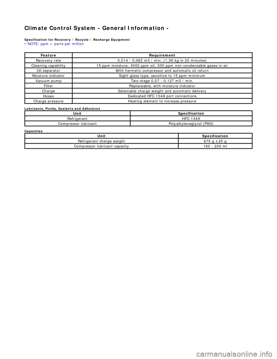
Climate Control System - General Informatio
n -
Sp
ecification for Recovery / Recycle / Recharge Equipment
•
NOTE: ppm = parts per million
Lubri
c
ants, Fluids, Sealants and Adhesives
Capacities
Fe at
ure
R
e
quirement
R
e
covery rate
0
,
014 - 0,062 m3 / min. (1,36 kg in 20 minutes)
Cleaning capability1
5 ppm
moisture; 4000 ppm oil; 330 ppm non-condensable gases in air
O
il se
parator
W
i
th hermetic compressor
and automatic oil return
Mois
ture indicator
Sigh
t-glass type, sensit ive to 15
ppm minimum
Vacuu
m
pump
Two-s
t
age 0,07 - 0,127 m3 / min.
Fi
lt
er
Replaceable, w
i
th
moisture indicator
ChargeSele
ctable charge weight and automatic delivery
HosesD
e
dicated HFC 134A port connections
Charge pressu
reHe
ating element to increase pressure
UnitS
p
ecification
Re
fr
i
geran
tHFC 134
A
Compressor lubricantP
ol
yalkyleneglycol (PAG)
UnitS
p
ecification
Re
fr
i
geran
t ch
ar
ge we
ight675 g ±2 5 g
Compressor lubricant capacity160
- 200 ml