weight JAGUAR X308 1998 2.G Workshop Manual
[x] Cancel search | Manufacturer: JAGUAR, Model Year: 1998, Model line: X308, Model: JAGUAR X308 1998 2.GPages: 2490, PDF Size: 69.81 MB
Page 43 of 2490
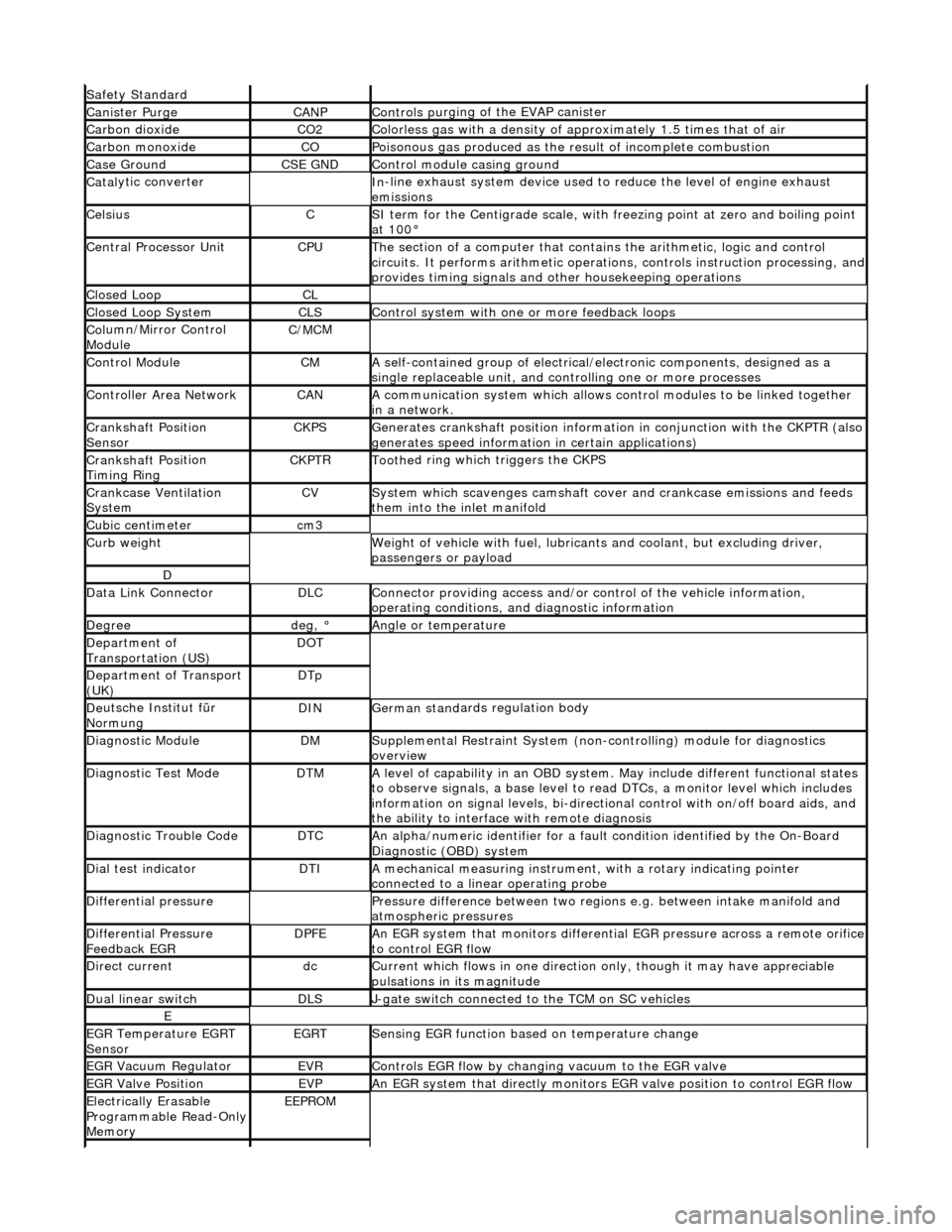
Safety Standard
Canister PurgeCANPControls pu
rging of the EVAP canister
Carbon dioxideCO2Colorless gas with
a density of a
pproximately 1.5 ti mes that of air
Carbon mon
oxide
COPoi
sonous gas produced as the re
sult of incomplete combustion
Case G
round
CSE GNDControl modu
le casing ground
Catal
ytic converter
In
-line exhaust system device used to reduce the level of engine exhaust
emissions
Ce
lsius
CSI ter
m for the Centigrade scale, with
freezing point at zero and boiling point
at 100°
Central
Processor Unit
CPUTh
e section of a computer that contai
ns the arithmetic, logic and control
circuits. It performs arithm etic operations, controls instruction processing, and
provides timing signals and other housekeeping operations
Cl
osed Loop
CL
Cl
osed Loop System
CLSControl
system with one
or more feedback loops
Col
umn/Mirror Control
Module
C/MC
M
Control ModuleCMA
self-contained group of electrical/electronic components, designed as a
single replaceable un it, and controlling one or more processes
Controll
er Area Network
CANA
communication system which allows control modules to be linked together
in a network.
Crankshaft Posi
tion
Sensor
CKPSGenerates crankshaft positi on informa
tion in conjunct
ion with the CKPTR (also
generates speed information in certain applications)
Crankshaft Posi
tion
Timing Ring
CKPT
R
Toothe
d ring which
triggers the CKPS
Crankcase Ventila
tion
System
CVSys
tem which scavenges camshaft cover and crankcase emissions and feeds
them into the inlet manifold
Cubic ce nt
imeter
cm
3
Curb weightWe
ight of vehicle with fuel, lubrican
ts and coolant, but excluding driver,
passengers or payload
D
Dat
a Link Connector
DLCConne
ctor providing access and/or control of the vehicle information,
operating conditions, and diagnostic information
De
gree
deg, °Angle or tempe
rature
D
epartment of
Transportation (US)
DO
T
D
epartment of Transport
(UK)
DTp
De
utsche In
stitut für
Normung
DINGerman stand
ards regulation body
Di
agnostic Module
DMSuppl
emental Restraint System (non-c
ontrolling) module for diagnostics
overview
Di
agnostic Test Mode
DTMA le
vel of capability in an OBD system.
May include different functional states
to observe signals, a base level to re ad DTCs, a monitor level which includes
information on signal levels, bi-directional control with on /off board aids, and
the ability to interface with remote diagnosis
Diagnostic Trouble CodeDTCAn al
pha/numeric identifier for a fault
condition identified by the On-Board
Diagnostic (OBD) system
D
ial test indicator
DTIA mechan
ical measuring
instrument, with a rotary indicating pointer
connected to a linear operating probe
D
ifferential pressure
Pressure di
fference betwee
n two regions e.g. between intake manifold and
atmospheric pressures
D
ifferential Pressure
Feedback EGR
DP
FE
An
EGR system that monito
rs differential EGR pressure across a remote orifice
to control EGR flow
D
irect current
dcCurrent which f
lows in on
e direction only, though it may have appreciable
pulsations in its magnitude
Du
al linear switch
DLSJ
-gate switch connected to the TCM on SC vehicles
E
EGR
Temperature EGRT
Sensor
EGRTSens
ing EGR function based on temperature change
EGR Vacu
um Regulator
EVRControls EGR
flow by changi
ng vacuum to the EGR valve
EGR Valve
Position
EVPAn EGR
system that direct
ly monitors EGR valve position to control EGR flow
Electrically E
rasable
Programmable Read-Only
Memory
EEP
ROM
Page 49 of 2490
Identification
Codes -
Identification Codes
Descr
iption and Operation
En
gine Number
The en
gine number (10 digits) is stamped on a raised pad on th
e front of the engine block near the thermostat housing. The
piston grade reference (8 digits) is also shown.
Automatic Transmission
Number
The
serial number of the transmission unit is displayed on
a metal or bar code label attached to the LH side of the
transmission casing.
Veh
icle Identification
Dependent
upon market, the VIN and other info
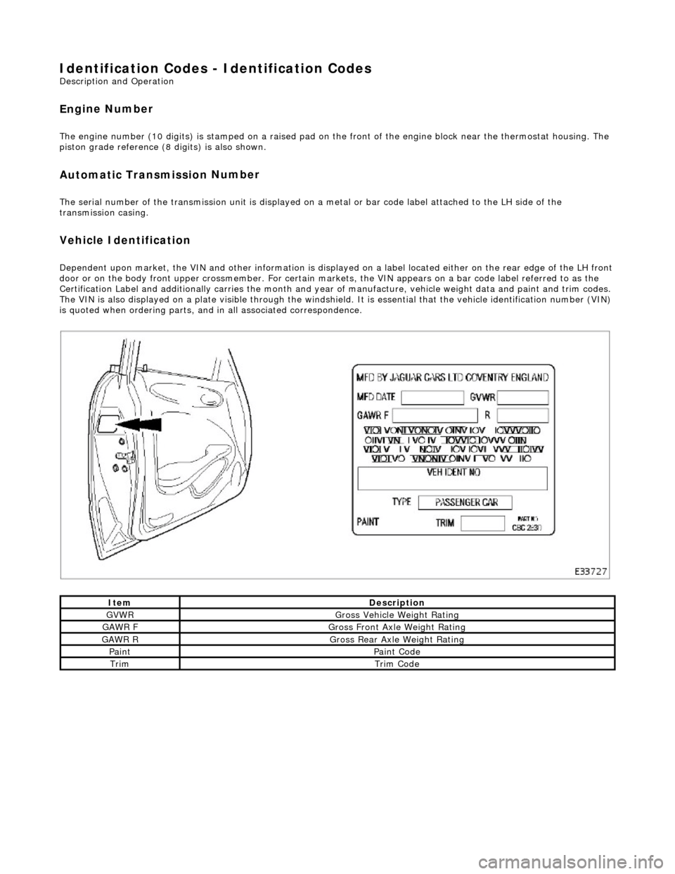
rmation is displayed on a label located ei ther on the rear edge of the LH front
door or on the body front upper crossmember. For certain mark ets, the VIN appears on a bar code label referred to as the
Certification Label and additionally carries the month and year of manufacture, vehicle weight data and paint and trim codes.
The VIN is also displayed on a plate visible through the windshie ld. It is essential that the vehicle identification number (VIN)
is quoted when ordering parts, and in all associated correspondence.
ItemDe
scription
GVW
R
G
ross Vehicle Weight Rating
GAW
R F
Gros
s Front Axle Weight Rating
GAW
R R
Gros
s Rear Axle Weight Rating
Pai
nt
Pai
nt Code
TrimTrim
Code
Page 50 of 2490
Date of
Manufacture
T
h
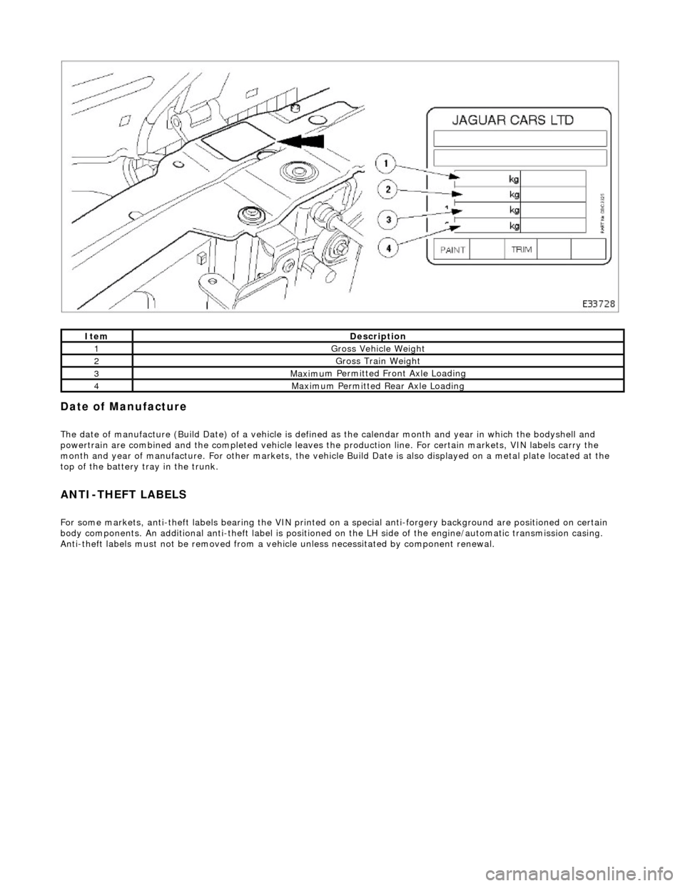
e date of manufacture (Build Date) of a vehicle is define
d as the calendar month and year in which the bodyshell and
powertrain are combined and the completed vehicle leaves the production line. For certain markets, VIN labels carry the
month and year of manufacture. For other markets, the vehicle Build Date is also displayed on a metal plate located at the
top of the battery tray in the trunk.
ANTI-T
HEFT LABELS
F
or
some markets, anti-theft labels bearing the VIN printed on
a special anti-forgery background are positioned on certain
body components. An additional anti-theft label is positioned on the LH side of the engine/automatic transmission casing.
Anti-theft labels must not be removed from a vehicle unless necessitated by component renewal.
ItemDe scrip
tion
1Gross Vehic
l
e Weight
2Gross Trai
n W
eight
3Maxim
u
m Permitted Front Axle Loading
4Maxim
u
m Permitted Rear Axle Loading
Page 70 of 2490
Upper
Wishbones
Each
upper wi
shbone assembly is a on
e-piece steel forging incorporating:
A pres
s-fit ball joint.
Press-fi
t bushes for location of the upper fulcrum bolt.
Lower Wishbones
Each l
o
wer wishbone comprising
forged steel front and rear arms bolted together, incorporates:
A p
ress-fit ball joint in the outer extremity of the rear arm.
Press-f
i
t bushes for location of the lower fulcrum bolts
Locati
on for the shock absor
b
er lower mounting plates.
Vertica l Links
The vertical
links are of forged steel
wi
th integral steering arms. Each is suppo rted between the upper and lower wishbones
by two ball joints and carries:
Front hub
Brake ca
liper and disc shield assembly
ABS se
nsor
.
Front Hub
s
Each f
o
rged steel front hub accommodates sealed for life cartridge
type wheel bearings, and carries:
The brake rotor assembl
y.
A
h
ub nut with toothed, integral ABS rotor.
Su
s
pension spring pi
n locking device.
Front Road
Springs
The road spri
ng
s are of coil type with their
rating dependent upon vehicle specification
Ea
ch spring is installed between the suspension crossbeam location and the lower wishbone spring pan.
Ru
bber seats ar
e installed betw
een the spring and the crossb eam and the spring pan.
Front Shock A
bsorbers
Th
e
shock absorbers are telescopic hydrau
lically operated units. Optional adaptive damping units incorporate a solenoid-
operated control valve at their upper extremity.
Each shoc
k absorber is installed between the lowe
r wishbone rear arm and a recess in the body.
The l
o
wer end of the shock absorber is se
cured to plates on the wishbone by a bolt that also serves as a pivot.
The u
pper en
d of each shock absorber is secured to the body location by a single nut.
Front Sta
b
ilizer Bar
A
front stabil
izer bar installed on all vehicles
is rated according to suspension specification.
Opera
tion
As each road wheel r
i
ses, move
ment is transmitted through the vertical link assembly to the lower wishbone. The resulting
rise of the wishbone compresses the road spring and partially telescopes the shock absorber. During this action, the spring
absorbs associated shocks and the shock absorber minimizes sprin
g os c
illation.
Du
ring cornering, vehicle weight
is transferred to the outer road wheel with a resulting tendency for the inner wheel to lift.
The stabilizer bar assists in minimizing this tendency by transf erring a proportion of potential lift of the inner wheel to the
outer wheel. This result s in enhanced body stability with improved corner ing capabilities.
Page 83 of 2490
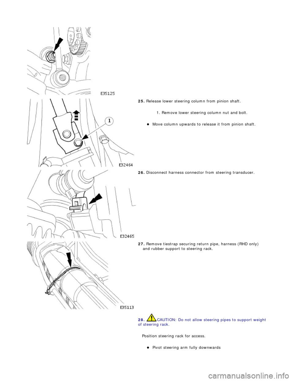
25
.
Release lower steering column from pinion shaft.
1. Remove lower steering column nut and bolt.
Move column up
wards to release it from pinion shaft.
26
.
Disconnect harness connector from steering transducer.
27
.
Remove tiestrap securing retu rn pipe, harness (RHD only)
and rubber support to steering rack.
28. CAUTION: Do not allow steerin g pipes to support weight
of steering rack.
Position steering rack for access.
Pi
vot steering arm fully downwards
Page 96 of 2490

28. CAU
TION: Do not allow steerin
g pipes to support weight
of steering rack.
Position steering rack for access.
Pivot steering arm ful
ly downwards
Re
move steering rack securing bolts.
Carefully move steer
ing rack
downwards for access to
wishbone eccentric bolt.
29 . R
emove lower wishbone rear
arm eccentric bolt and nut.
Mark position of eccentri
c bo
lt large graduation mark on
crossbeam.
Remove wish
bone eccent
ric bolt and nut.
30. Remove lower wishbone rear arm/ball joint assembly from
crossbeam.
31 . R
emove lower wishbone front
arm eccentric bolt and nut.
Mark position of eccentri
c bo
lt large graduation mark on
crossbeam.
Re
move wishbone front ec
centric bolt and nut.
32. Remove lower wishbone front arm from crossbeam.
33. NOTE: For assembly purposes, note orientation of bush.
• NOTE: Initial press action will cause tool to sh ear bush flange.
Using a hydraulic press, remove bush from wishbone front arm.
Page 153 of 2490
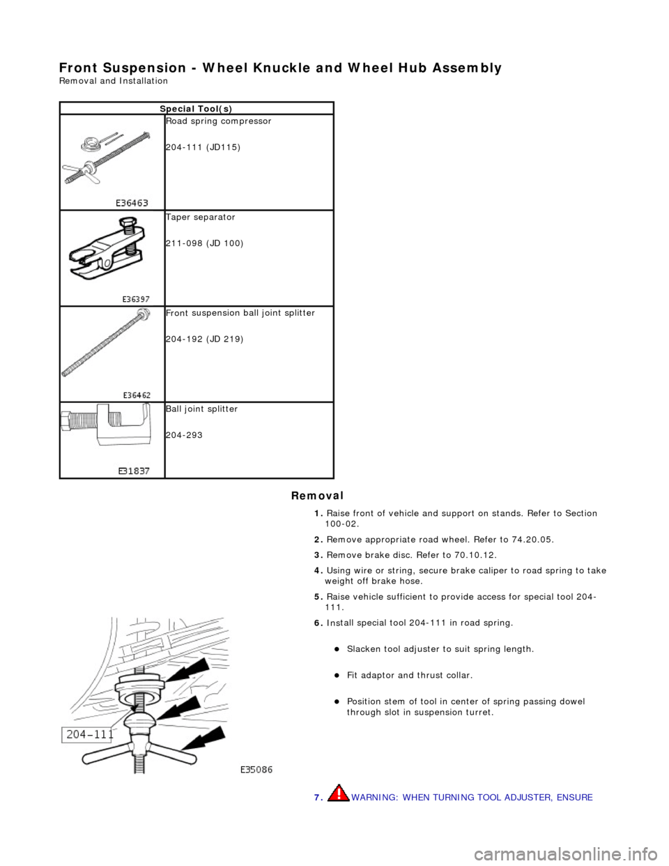
Front Susp
ension - Wheel Knuckle and Wheel Hub Assembly
Re
moval and Installation
Remov
al
S
pecial Tool(s)
R
oad spring compressor
204-111 (JD115)
Taper separator
211-098 (JD 100)
Front
suspension ball joint splitter
204-192 (JD 219)
Bal
l joint splitter
204-293
1. Raise front of vehicle and support on stands. Refer to Section
100-02.
2. Remove appropriate road wheel. Refer to 74.20.05.
3. Remove brake disc. Refer to 70.10.12.
4. Using wire or string, secure brak e caliper to road spring to take
weight off brake hose.
5. Raise vehicle sufficient to provide access for special tool 204-
111.
6. Ins
tall special tool 204-111 in road spring.
Sl
acken tool adjuster to suit spring length.
Fit adaptor and th
rust collar.
Posit
ion stem of tool in center of spring passing dowel
through slot in su spension turret.
7. WARNING: WHEN TURNING TOOL ADJUSTER, ENSURE
Page 159 of 2490

Front Susp
ension - Wheel
Knuckle and Wheel Hub Assembly Conversion
Re
moval and Installation
Remov
al
S
pecial Tool(s)
R
oad spring compressor
204-111 (JD115)
Taper separator
211-098 (JD 100)
Front
suspension ball joint splitter
204-192 (JD 219)
Bal
l joint splitter
204-293
1. Raise front of vehicle and support on stands. Refer to Section
100-02.
2. Remove appropriate road wheel. Refer to 74.20.05.
3. Remove brake disc. Refer to 70.10.12.
4. Using wire or string, secure brak e caliper to road spring to take
weight off brake hose.
5. Raise vehicle sufficient to provide access for special tool 204-
111.
6. R
emove nut and bolt securing stabilizer bar link arm to lower
wishbone.
7. Remove nut securing link arm ba ll joint to stabilizer bar and
remove link arm from vehicle.
Page 168 of 2490
Each r
oad spring and is located between the wishbone in
tegral spring seat and the body suspension turret.
Each shoc
k absorber unit is installed
co-axially within the road spring.
The lo
wer end of each shock absorber is secured to the
wishbone by a bolt which also functions as a pivot.
Adaptive damping is av
ailable as an option.
A
rear stabi
lizer bar is installed on
Supercharged and Sport Suspension models . Mounted at the rear of the wishbone
tie assembly, the stabilizer bar is connected to the wishbone by short links.
Op era
tion
As each road wheel r
i
ses, move
ment is transmitted through th e hub carrier assembly to the wishbone and axle shaft. The
corresponding rise of the wishbone compre sses the road spring and partially telescopes the shock absorber. During this
action, the spring absorbs result ing shocks and the shock absorber minimizes spring oscillation.
During cornering, vehicle weight is transferred to the outer road wheel with a resulting tendency for the inner wheel to lift.
On Supercharged and Sport Suspension vehicl es, a rear stabilizer bar assists in minimizing this tendency by transferring a
proportion of potential lift of the inner wheel to the outer wheel. This results in enhanced body stability with improved
cornering capabilities.
Page 174 of 2490
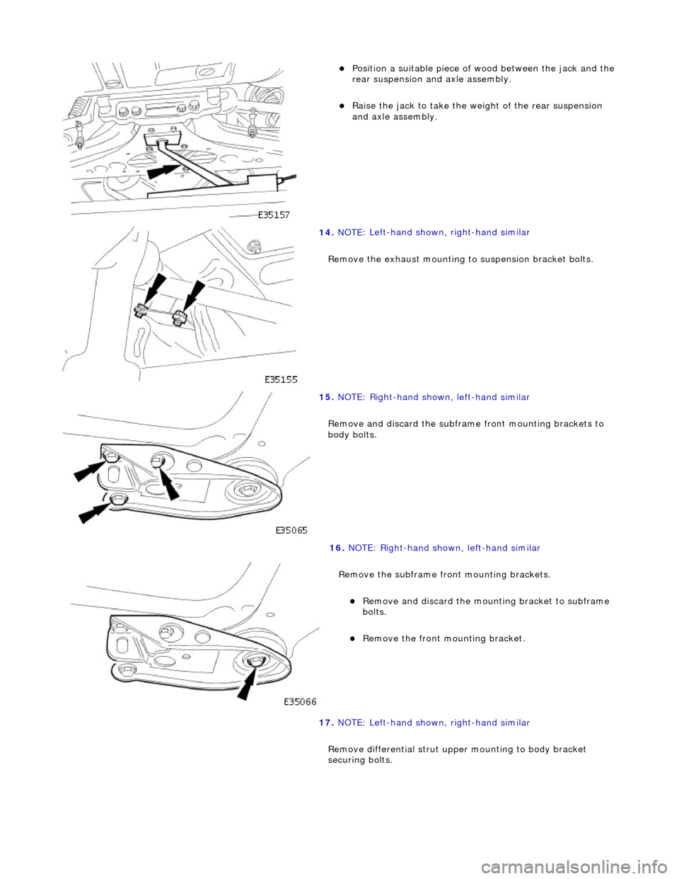
Position a suitable piece o
f wood between the jack and the
rear suspension and axle assembly.
Rai s
e the jack to take the weight of the rear suspension
and axle assembly.
14 . NOTE
: Left-hand shown, right-hand similar
Remove the exhaust mounting to suspension bracket bolts.
15 . NOTE
: Right-hand shown, left-hand similar
Remove and discard the subframe front mounting brackets to
body bolts.
16 . NOTE
: Right-hand shown, left-hand similar
Remove the subframe front mounting brackets.
Remove an d discard the mount
ing bracket to subframe
bolts.
R e
move the front mounting bracket.
17. NOTE: Left-hand shown, right-hand similar
Remove differential strut upper mounting to body bracket
securing bolts.