weight JAGUAR X308 1998 2.G Owner's Manual
[x] Cancel search | Manufacturer: JAGUAR, Model Year: 1998, Model line: X308, Model: JAGUAR X308 1998 2.GPages: 2490, PDF Size: 69.81 MB
Page 1756 of 2490
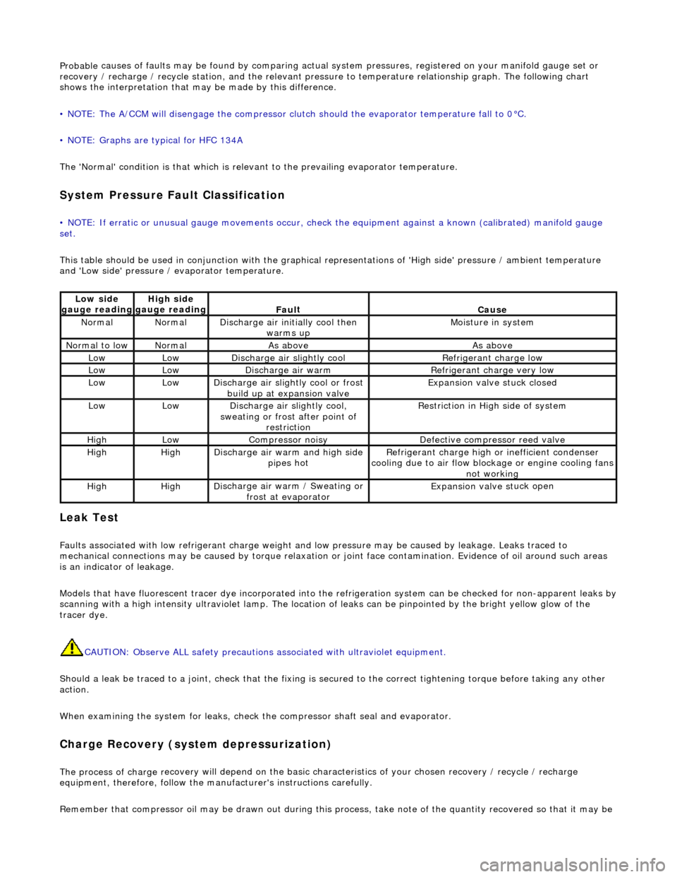
Probable
causes of faults may be found by comparing actual
system pressures, registered on your manifold gauge set or
recovery / recharge / recycle station, and the relevant pressure to temperature relationship graph. The following chart
shows the interpretation that ma y be made by this difference.
• NOTE: The A/CCM will disengage the compressor clutch should the evaporator temperature fall to 0°C.
• NOTE: Graphs are typical for HFC 134A
The 'Normal' condition is that which is relevant to the prevailing evaporator temperature.
System Pressure Fault Classification
• NOTE
: If erratic or unusual gauge move
ments occur, check the equipment against a known (calibrated) manifold gauge
set.
This table should be used in conjunction with the graphical representations of 'High side' pressure / ambient temperature
and 'Low side' pressure / evaporator temperature.
Leak
Test
F
a
ults associated with low re
frigerant charge weight and low pressure ma y be caused by leakage. Leaks traced to
mechanical connections may be caused by to rque relaxation or joint face contamination. Evidence of oil around such areas
is an indicator of leakage.
Models that have fluorescent tracer dye incorporated into the refrigeration system can be checke d for non-apparent leaks by
scanning with a high intensity ultraviolet lamp. The location of leaks can be pinpointed by the bright yellow glow of the
tracer dye.
CAUTION: Observe ALL safety precautions associated with ultraviolet equipment.
Should a leak be traced to a joint, check that the fixing is secured to the correct tightening torque before taking any other
action.
When examining the system for leaks, chec k the compressor shaft seal and evaporator.
Charge Re
covery (system depressurization)
The process of
charge r
ecovery will depe
nd on the basic characteristics of your chosen recovery / recycle / recharge
equipment, therefore, follow the manu facturer's instructions carefully.
Remember that compressor oil may be drawn out during this process, take note of the quantity recovered so that it may be
Lo
w side
gauge reading
High s i
de
gauge reading
Fau l
t
Cause
No
r
mal
No
r
mal
Di
sc
harge air initially cool then
warms up
Mois
ture in system
N
ormal
to low
No
r
mal
As aboveAs above
LowLowD
i
scharge air slightly cool
Ref
r
igerant charge low
LowLowDi
scharge air warm
Refr
igerant charge very low
LowLowDi
scharge air slightly cool or frost
build up at expansion valve
Expansion valve st
uck closed
LowLowDi
scharge air slightly cool,
sweating or frost after point of restriction
Restri
ction in High side of system
HighLowCompressor noisyDe
fe
ctive compressor reed valve
HighHighD
i
scharge air warm and high side
pipes hot
Refri
gerant charge high or inefficient condenser
cooling due to air flow blockage or engine cooling fans
not working
HighHighD i
scharge air warm / Sweating or
frost at evaporator
Expans ion valve st
uck open
Page 1762 of 2490
Climate Control System - General Infor
mation - Air Conditioning (A/C)
System Recovery, Evacuation and Charging
Gen e
ral Procedures
Recover / Reclaim
Ev
acuation
Charging
1.
CAUTIO
N: Read the procedures and instructions supplied
by the manufacturer of the air co nditioning service center before
commencing any process requiring the handling of refrigerant. In
addition to the manufacturer's in formation, observe all safety
precautions and advice deta iled in this section.
Disconnect battery ground lead; refer to 86.15.19.
2. Remove passenger side fi
rewall cover.
3. Remove driver side firewall cover.
4. Remove engine compar tment rear cover.
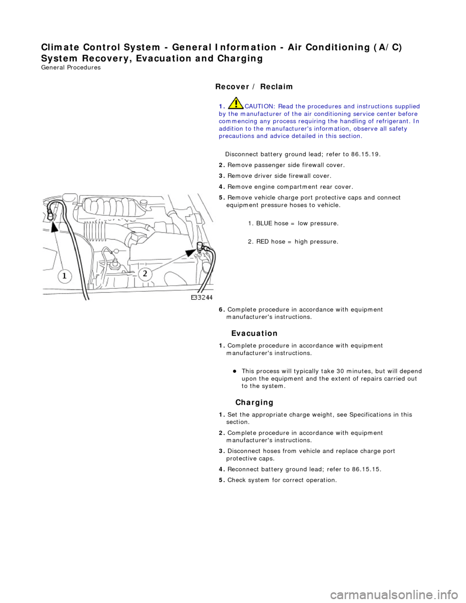
5. Re
move vehicle charge port
protective caps and connect
equipment pressure hoses to vehicle.
1. BLUE hose = low pressure.
2. RED hose = high pressure.
6. Complete procedure in ac cordance with equipment
manufacturer's instructions.
1. Complete procedure in ac cordance with equipment
manufacturer's instructions.
This proc
ess will typically ta
ke 30 minutes, but will depend
upon the equipment and the ex tent of repairs carried out
to the system.
1. Set the appropriate charge weight, see Specifications in this
section.
2. Complete procedure in ac cordance with equipment
manufacturer's instructions.
3. Disconnect hoses from vehicle and replace charge port
protective caps.
4. Reconnect battery ground lead; refer to 86.15.15.
5. Check system for correct operation.
Page 1765 of 2490
Climate Co
ntrol System - General
Information - Refrigerant Adding
Gen
eral Procedures
CAUTION: If oil was drawn out during the recovery process, the correct amount may be added directly from the
recovery, recycle and recharge station (if so equipped) prior to the charging process. It must be stressed that the need to
protect compressor oil from moisture is vital, observe the pr ocedures in HANDLING LUBRICATING OIL and those concerning
excessive engine speed.
1. In order that the
air conditioning system may operate
efficiently it must contain a full refrigerant charge. The
indications of some system defects, and the results of certain
tests, will show that a low charge is the most probable cause of
the fault. In such cases the ch arge should be recovered from
the system, the weight noted, and the correct amount added.
Should refrigerant be added in liquid form, the engine speed
must not exceed 2000 rpm for a period of two minutes after
first running the compressor. If the engine speed is excessive,
compressor damage may occur du e to the lubricating oil and
the liquid refrigerant being initia lly forced around the system as
a 'slug', thus taking oil away from the compressor. These
marginal lubrication conditions in the compressor will cease as
the refrigerant becomes gaseous.
Never attempt to estimate the amount of refrigerant in a
system. Always recover and rech arge with the correct charge
weight; this is the only accurate method.
Page 1876 of 2490
Battery, Mounting and Cables - Battery and Cables Description and Operation
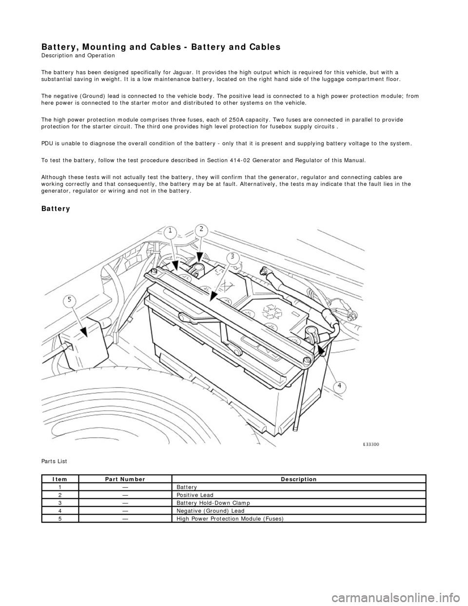
The battery has been designed specifically for Jaguar. It provides the high output which is required for this vehicle, but with a
substantial saving in weight. It is a low maintenance battery, located on the right ha nd side of the luggage compartment floor.
The negative (Ground) lead is connected to the vehicle body. The positive lead is connected to a high power protection module; from
here power is connected to the starter motor an d distributed to other systems on the vehicle.
The high power protection module comprises three fuses, each of 250A capacity. Two fuses are connected in parallel to provide
protection for the starter circuit. Th e third one provides high level protection for fusebox supply circuits .
PDU is unable to diagnose the overall condition of the battery - only that it is present and supplying battery voltage to the system.
To test the battery, follow the test procedure described in Section 414-02 Generator and Regulator of this Manual.
Although these tests will not actually test the battery, they will confirm that the generator, regulator and connecting cables are
working correctly and that conseq uently, the battery may be at fault. Alternatively, the tests may indicate that the fault lies in the
generator, regulator or wiring and not in the battery.
Battery
Parts List
ItemPart NumberDescription
1—Battery
2—Positive Lead
3—Battery Hold-Down Clamp
4—Negative (Ground) Lead
5—High Power Protection Module (Fuses)
Page 2021 of 2490
Body System - General Information - Body
Description and Operation
This section covers the following areas of the vehicle body:
Front end body panels
Body closures
Aperture seals
Door seals
Instrument panel, console and radio
Centre console
Handles, locks, latches and mechanisms
Wipers and washers
Glass, frames and mechanisms
Fascia
Fuel filler flap assembly
Sun visors
Seating
Interior trim and ornamentation
Exterior trim and ornamentation
Rear view mirrors
Rear parcel tray
Roof console
Bumpers
Occupant restraints
Sliding roof
Steering column cowl
Underscuttle pad
Front End Body Panels
A false bulkhead together with two insulation covers, are installed between the engine compartment and the BIW front
bulkhead to provide optimum insulation ag ainst noise and heat intrusion. Two plenum braces bolted between the BIW upper toeboards and the plenum further increase bodyshell structural integrity. The plastic ra diator grill and vane block achieve
weight reductions over steel parts and provid e high resistance to front end corrosion.
Page 2027 of 2490
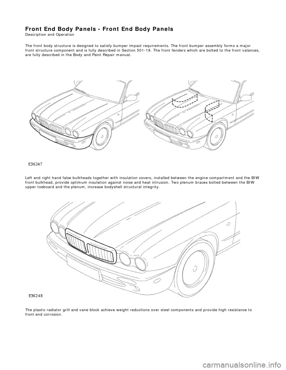
Front End Body Panels - Front End Body Panels
Description and Operation
The front body structure is de signed to satisfy bumper impact requiremen ts. The front bumper assembly forms a major
front structure component and is fully desc ribed in Section 501-19. The front fenders which are bolted to the front valances,
are fully described in the Body and Paint Repair manual.
Left and right hand false bulkheads together with insulation covers, installed between the engine compartment and the BIW
front bulkhead, provide optimum insulation against noise and heat intrusion. Two plenum braces bolted between the BIW
upper toeboard and the plenum, increa se bodyshell structural integrity.
The plastic radiator grill and vane block achieve weight reductions over steel components and provide high resistance to
front end corrosion.
Page 2421 of 2490
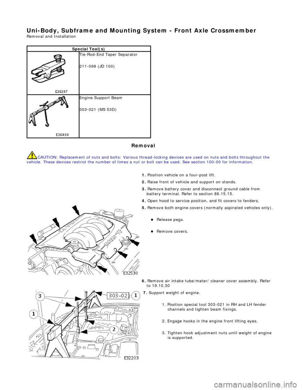
Uni-Body, Subframe and Mounting System - Front Axle Crossmember
Removal and Installation
Removal
CAUTION: Replacement of nuts and bolts: Various thread-locking devices are used on nuts and bolts throughout the
vehicle. These devices restrict the number of times a nut or bolt can be used. See section 100-00 for information.
Special Tool(s)
Tie-Rod-End Taper Separator
211-098 (JD 100)
Engine Support Beam
303-021 (MS 53D)
1. Position vehicle on a four-post lift.
2. Raise front of vehicle and support on stands.
3. Remove battery cover and disc onnect ground cable from
battery terminal. Refer to section 86.15.15.
4. Open hood to service position, and fit covers to fenders.
5. Remove both engine covers (nor mally aspirated vehicles only).
Release pegs.
Remove covers.
6. Remove air intake tube/meter/ cleaner cover assembly. Refer
to 19.10.30
7. Support weight of engine.
1. Position special tool 303-021 in RH and LH fender channels and tighte n beam fixings.
2. Engage hooks in the en gine front lifting eyes.
3. Tighten hook adjustment nuts until weight of engine is supported.
Page 2425 of 2490
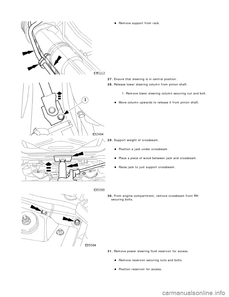
Remove support from rack.
27. Ensure that steering is in central position.
28. Release lower steering column from pinion shaft.
1. Remove lower steering co lumn securing nut and bolt.
Move column upwards to release it from pinion shaft.
29. Support weight of crossbeam.
Position a jack under crossbeam.
Place a piece of wood between jack and crossbeam.
Raise jack to just support crossbeam.
30. From engine compartment, remove crossbeam front RH
securing bolts.
31. Remove power steering fl uid reservoir for access.
Remove reservoir securing nuts and bolts.
Position reservoir for access.
Page 2434 of 2490
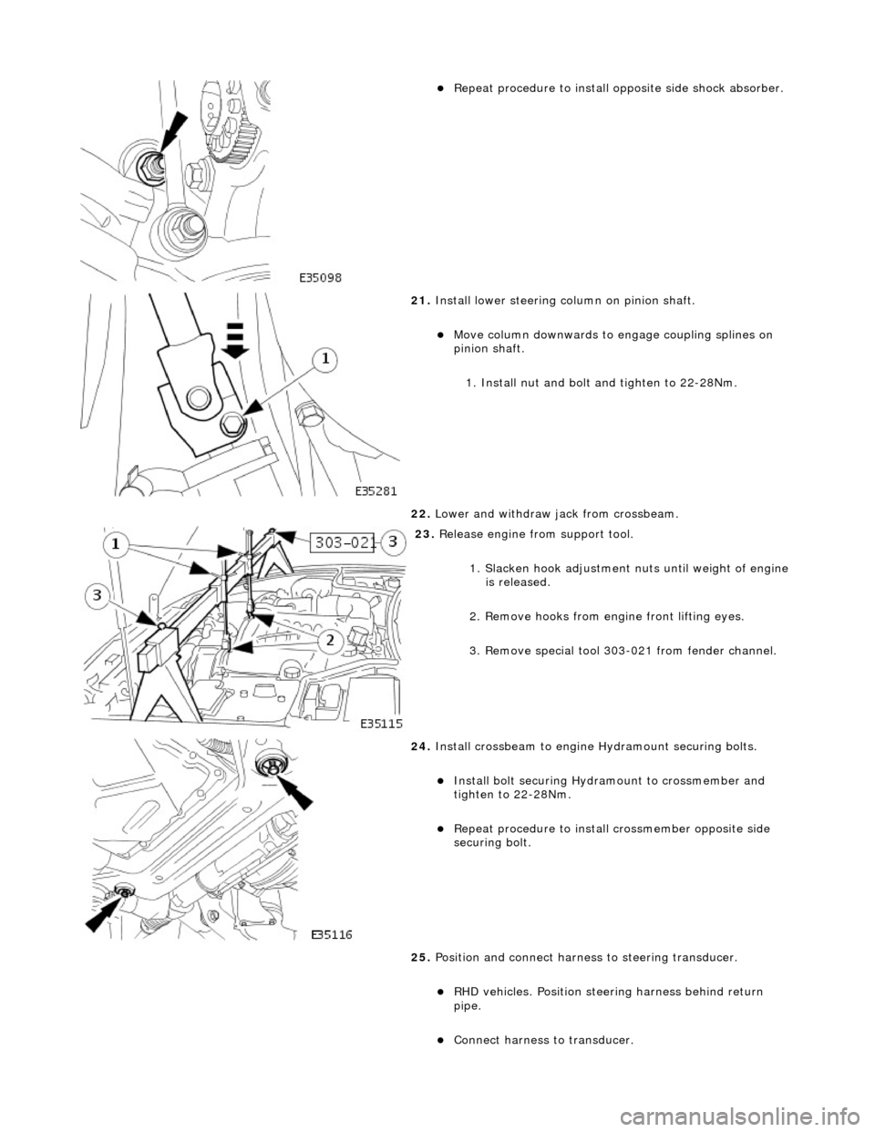
Repeat procedure to install opposite side shock absorber.
21. Install lower steering column on pinion shaft.
Move column downwards to engage coupling splines on
pinion shaft.
1. Install nut and bolt and tighten to 22-28Nm.
22. Lower and withdraw jack from crossbeam.
23. Release engine from support tool.
1. Slacken hook adjustment nuts until weight of engine is released.
2. Remove hooks from engine front lifting eyes.
3. Remove special tool 303- 021 from fender channel.
24. Install crossbeam to engine Hydramount securing bolts.
Install bolt securing Hydr amount to crossmember and
tighten to 22-28Nm.
Repeat procedure to install crossmember opposite side
securing bolt.
25. Position and connect harnes s to steering transducer.
RHD vehicles. Position steeri ng harness behind return
pipe.
Connect harness to transducer.
Page 2439 of 2490
Uni-Body, Subframe and Mounting System - Front Axle Crossmember
Front Bushing
Removal and Installation
Removal
CAUTION: Replacement of nuts and bolts: Various thread-locking devices are used on nuts and bolts throughout the
vehicle. These devices restrict the number of times a nut or bolt can be used. See Section 100-00 for information.
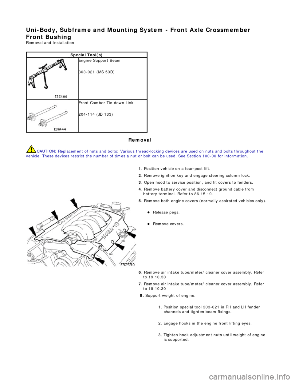
Special Tool(s)
Engine Support Beam
303-021 (MS 53D)
Front Camber Tie-down Link
204-114 (JD 133)
1. Position vehicle on a four-post lift.
2. Remove ignition key and en gage steering column lock.
3. Open hood to service position, and fit covers to fenders.
4. Remove battery cover and disc onnect ground cable from
battery terminal. Refer to 86.15.19.
5. Remove both engine covers (nor mally aspirated vehicles only).
Release pegs.
Remove covers.
6. Remove air intake tube/meter/ cleaner cover assembly. Refer
to 19.10.30
7. Remove air intake tube/meter/ cleaner cover assembly. Refer
to 19.10.30
8. Support weight of engine.
1. Position special tool 303-021 in RH and LH fender channels and tighte n beam fixings.
2. Engage hooks in the en gine front lifting eyes.
3. Tighten hook adjustment nuts until weight of engine is supported.