303 JAGUAR X308 1998 2.G Workshop Manual
[x] Cancel search | Manufacturer: JAGUAR, Model Year: 1998, Model line: X308, Model: JAGUAR X308 1998 2.GPages: 2490, PDF Size: 69.81 MB
Page 1231 of 2490
Is th
e voltage greater than 3 volts?
Yes REPAIR the short circuit. For addi tional information, refer to the wiring diagrams. CLEAR the DTC.
TEST the system for normal operation.
No GO to AB3
.
AB3
: CHECK THE RADIATOR FAN MODULE TO ECM
'PARALLEL' DRIVE CIRCUIT FOR SHORT TO GROUND
Turn the ignition swi
tch to the OFF
position.
1
Meas
ure the resistance between EM13, pin 16 (WU) and GROUND.
2
Is
the resistance less than 10,000 ohms?
Yes
REPAIR the short circuit. For addi tional information, refer to the wiring diagrams. CLEAR the DTC.
TEST the system for normal operation.
No GO to AA4
.
AB4
: CHECK THE RADIATOR FAN MODULE IGNITION SUPPLY
Re
connect the ECM electrical connector, EM13.
1
Turn the ignition swi
tch to the ON
position.
2
Measure the
voltage between LS
31, pin 08 (WP) and GROUND.
3
Is the vol
tage greater than 10 volts?
Yes INSTALL a new radiator fan module. REFER to Section 303
-0
3A Engine Cooling
/
30
3
-03
B
Supercharger
Cooling
. CLEA
R the DTC. TEST the sy
stem for normal operation.
No REPAIR the circuit between LS31, pin 08 (WP) and battery. This circuit includes the EMS fuse box-
(fuse 14), the EMS relay, etc. For additional information, refer to the wiring diagrams. CLEAR the
DTC. TEST the system for normal operation.
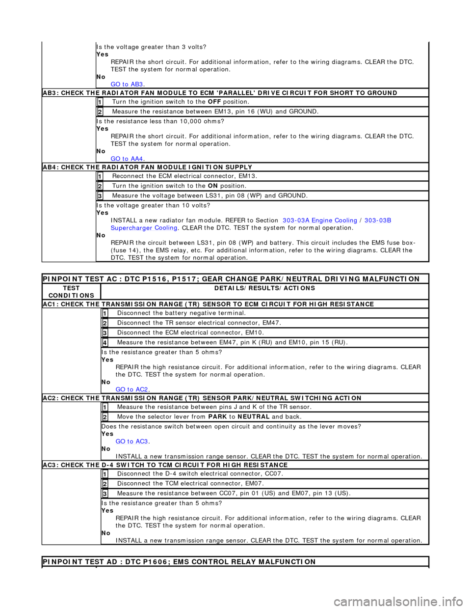
P
INPOINT TEST AC : DTC P1516, P1517; GEAR
CHANGE PARK/NEUTRAL DRIVING MALFUNCTION
TE
ST
CONDITIONS
D
ETAILS/RESULTS/ACTIONS
AC1: CH
ECK THE TRANSMISSION RANGE (TR) SE
NSOR TO ECM CIRCUIT FOR HIGH RESISTANCE
Di
sconnect the battery negative terminal.
1
Di
sconnect the TR sensor el
ectrical connector, EM47.
2
D
isconnect the ECM electrical connector, EM10.
3
Meas
ure the resistance between EM47, pin K (RU) and EM10, pin 15 (RU).
4
Is th
e resistance greater than 5 ohms?
Yes REPAIR the high resistance circui t. For additional information, refer to the wiring diagrams. CLEAR
the DTC. TEST the system for normal operation.
No GO to AC2
.
AC2: CH
ECK THE TRANSMISSION RANGE (TR)
SENSOR PARK/NEUTRAL SWITCHING ACTION
Meas
ure the resistance between pi
ns J and K of the TR sensor.
1
Mo
ve the selector lever from
PARK to NEUTRAL and back.
2
D
oes the resistance switch between open ci
rcuit and continuity as the lever moves?
Yes GO to AC3
.
No
INSTALL a new transmission range sensor. CLEAR th e DTC. TEST the system for normal operation.
AC3: CH
ECK THE D-4 SWITCH TO
TCM CIRCUIT FOR HIGH RESISTANCE
Di
sconnect the D-4 switch electrical connector, CC07.
1
Di
sconnect the TCM electrical connector, EM07.
2
Meas
ure the resistance between CC07,
pin 01 (US) and EM07, pin 13 (US).
3
Is th
e resistance greater than 5 ohms?
Yes REPAIR the high resistance circui t. For additional information, refer to the wiring diagrams. CLEAR
the DTC. TEST the system for normal operation.
No INSTALL a new transmission range sensor. CLEAR th e DTC. TEST the system for normal operation.
P
INPOINT TEST AD : DTC P1606;
EMS CONTROL RELAY MALFUNCTION
Page 1262 of 2490
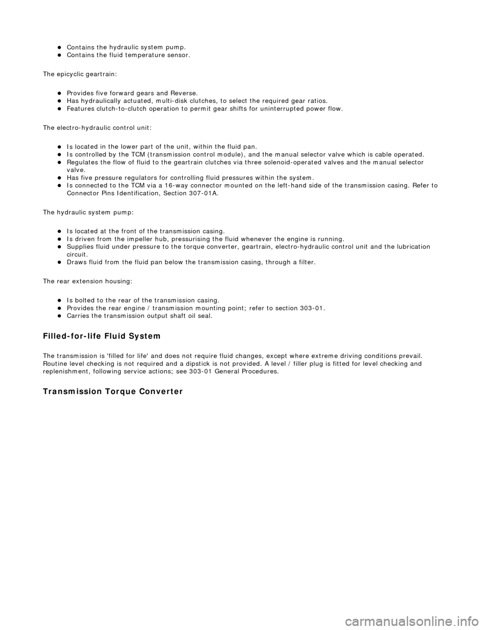
пЃ¬Contains th
e hydraulic system pump.
пЃ¬Contains
th
e fluid temperature sensor.
The epicyclic geartrain:
пЃ¬Provi des fi
ve forward gears and Reverse.
пЃ¬Has
h
ydraulically actuated, multi-disk clutches, to select the required gear ratios.
пЃ¬Feature
s clutch-to-clutch operation to permit
gear shifts for uninterrupted power flow.
The electro-hydraulic control unit:
пЃ¬Is lo c
ated in the lower part of
the unit, within the fluid pan.
пЃ¬Is controlled
by the TCM (transmissio
n control module), and the manual selector valve which is cable operated.
пЃ¬Re
gulates the flow of fluid to the ge
artrain clutches via three solenoid-operated valv es and the manual selector
valve.
пЃ¬Has fi ve pressure
regulators for controll
ing fluid pressures within the system.
пЃ¬Is con
nected to the TCM via a 16-way connector mounted on
the left-hand side of the transmission casing. Refer to
Connector Pins Identification, Section 307-01A.
The hydraulic system pump:
пЃ¬Is l o
cated at the front of the transmission casing.
пЃ¬Is dri
v
en from the impeller hub,
pressurising the fluid whenever the engine is running.
пЃ¬Supplie
s fluid under pressure to the torq
ue converter, geartrain, electro-hydr aulic control unit and the lubrication
circuit.
пЃ¬D r
aws fluid from the fluid pa
n below the transmission casing, through a filter.
The rear extension housing:
пЃ¬Is bolt
ed to the rear of the transmission casing.
пЃ¬Provides the rear engine / transmi
ssion mo
unting point; refer to section 303-01.
пЃ¬Carrie
s the transmission output shaft oil seal.
Filled-for-l
i
fe Fluid System
The
transm
ission is 'filled for life' and
does not require fluid changes, except where extreme driving conditions prevail.
Routine level checking is not required and a dipstick is not pr ovided. A level / filler plug is fitted for level checking and
replenishment, following service actions; see 303-01 General Procedures.
Transmission Torque Converter
Page 1271 of 2490
Controller Area Network (CAN)
The TCM is an integral part of the CAN system which facilitates the interchange of real-time data between control modules
and sensors. Please see section 303- 14 for a full description of CAN.
OBDII Interface
Data concerning OBDII related transmission failures is stored in the ECM for access via the J1962 socket.
System Functions
Range Selection
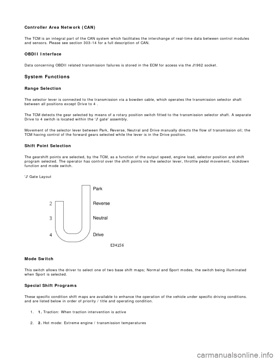
The selector lever is connected to the transmission via a bowden cable, which operates the transmission selector shaft
between all positions except Drive to 4 .
The TCM detects the gear selected by means of a rotary position switch fitted to the transmission selector shaft. A separate
Drive to 4 switch is located within the 'J' gate' assembly.
Movement of the selector lever between Park, Reverse, Neutral and Drive manually directs th e flow of transmission oil; the
TCM having control of the forward gears selected while the lever is in the Drive position.
Shift Point Selection
The gearshift points are selected, by the TCM, as a function of the output speed, engine load, selector position and shift
program selected. The operator has control over the shift points via the selector lever, throttle pedal movement, kickdown
function and mode switch.
'J' Gate Layout
Mode Switch
This switch allows the driver to select one of two base shift maps; Normal and Sport modes, the switch being illuminated
when Sport is selected.
Special Shift Programs
These specific condition shift maps are available to enhance the operation of the vehicle under specific driving conditions.
and are listed below in order of priority / title and operating condition.
1. 1. Traction: When traction intervention is active
2. 2. Hot mode: Extreme engine / transmission temperatures
Page 1375 of 2490

Automatic Transmission/Transaxle - 4.0L NA V8 - AJ27/3.2L NA V8 - AJ26
- Transmission
Removal
Removal
Special Tool(s)
Engine support
303-021
Engine lifting brackets
303-536
1. Select N gear position.
2. Open the engine compartment and fit paintwork protection
sheets.
3. Disconnect battery ground cable.
пЃ¬Remove the battery cover.
4. Remove the engine covers (12.30.06).
5. Remove the air intake tube, MAFM and air cleaner cover assy,
(19.10.30).
6. Install engine lifting bracket 303 - 536 at the rear RH.
7. Reposition the coolant he ader tank for access.
1. Remove the securing bolt.
Page 1376 of 2490

2. Reposition the tank.
8. Install engine lifting bracket 303 - 536 at the rear LH.
9. Support the engine using 303 - 021.
1. Adjust and locate the stan ds in the LH and RH fender
channels and tighten the beam fixings.
2. Engage the support hook s in the lifting brackets.
3. Tighten the support hook adjusters and take the weight of the engine.
10. Raise the vehicle for access.
11. Remove the LH downpipe cata lytic converter (17.50.09).
12. Remove the front muffler (30.10.18).
13. Remove the RH downpipe catalytic converter (17.50.09 and
17.50.10).
14. Drain the transmission fluid, (44.24.02).
15. Locate a transmission jack, Epco V-100 or similar, under the
transmission unit.
пЃ¬Adjust the angle of the jack to suit the transmission.
пЃ¬Secure the side clamps.
пЃ¬Pass the safety chain over the transmission unit and
secure.
Page 1383 of 2490
Automatic Transmission/Transaxle - 4.0L NA V8 - AJ27/3.2L NA V8 - AJ26
- Transmission
Installation
Installation
Special Tool(s)
Engine support
303-021
Engine lifting brackets
303-536
1. Clean all mating faces and relevant parts.
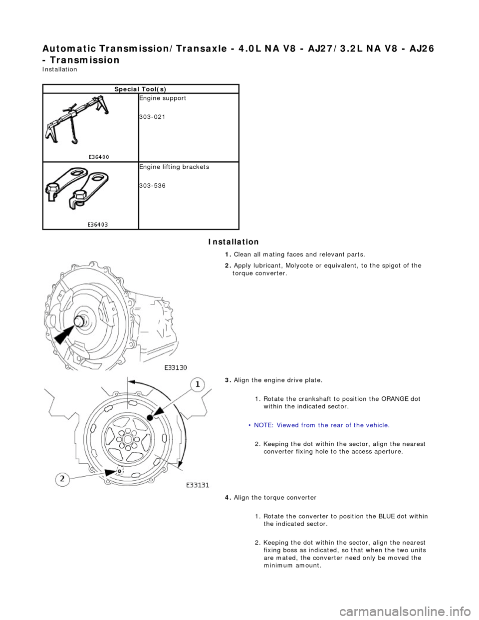
2. Apply lubricant, Molycote or equivalent, to the spigot of the
torque converter.
3. Align the engine drive plate.
1. Rotate the crankshaft to position the ORANGE dot
within the indicated sector.
• NOTE: Viewed from the rear of the vehicle.
2. Keeping the dot within the sector, align the nearest converter fixing hole to the access aperture.
4. Align the torque converter
1. Rotate the converter to position the BLUE dot within the indicated sector.
2. Keeping the dot within the sector, align the nearest fixing boss as indicated, so that when the two units
are mated, the converter need only be moved the
minimum amount.
Page 1386 of 2490
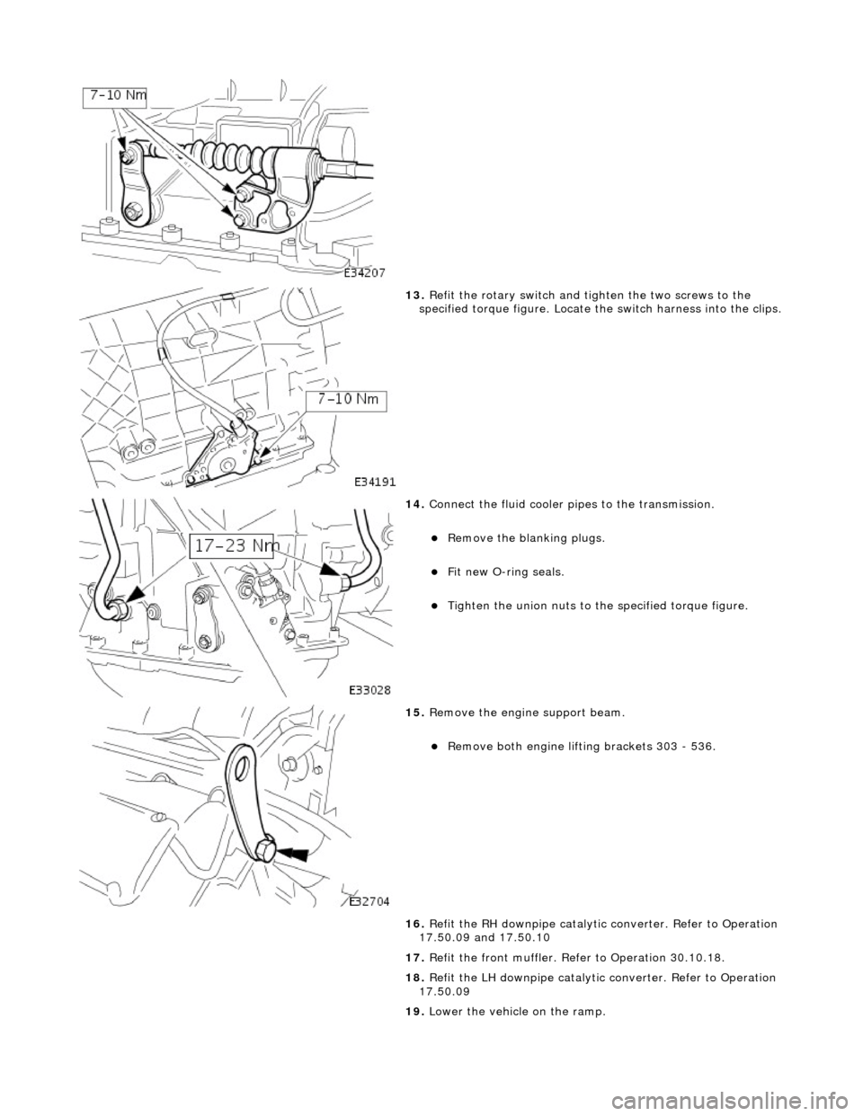
13. Refit the rotary switch and tighten the two screws to the
specified torque figure. Locate the switch harness into the clips.
14. Connect the fluid cooler pipes to the transmission.
пЃ¬Remove the blanking plugs.
пЃ¬Fit new O-ring seals.
пЃ¬Tighten the union nuts to the specified torque figure.
15. Remove the engine support beam.
пЃ¬Remove both engine lifting brackets 303 - 536.
16. Refit the RH downpipe catalytic converter. Refer to Operation
17.50.09 and 17.50.10
17. Refit the front muffler. Refer to Operation 30.10.18.
18. Refit the LH downpipe catalytic converter. Refer to Operation
17.50.09
19. Lower the vehicle on the ramp.
Page 1395 of 2490
and/or increased performance as appropriate.
Serial Communications Interfaces
Controller Area Network (CAN)
The TCM is an integral part of the CAN system which facilita tes the interchange of real-time data between control modules
and sensors; refer to 303-14 fo r a full description of CAN.
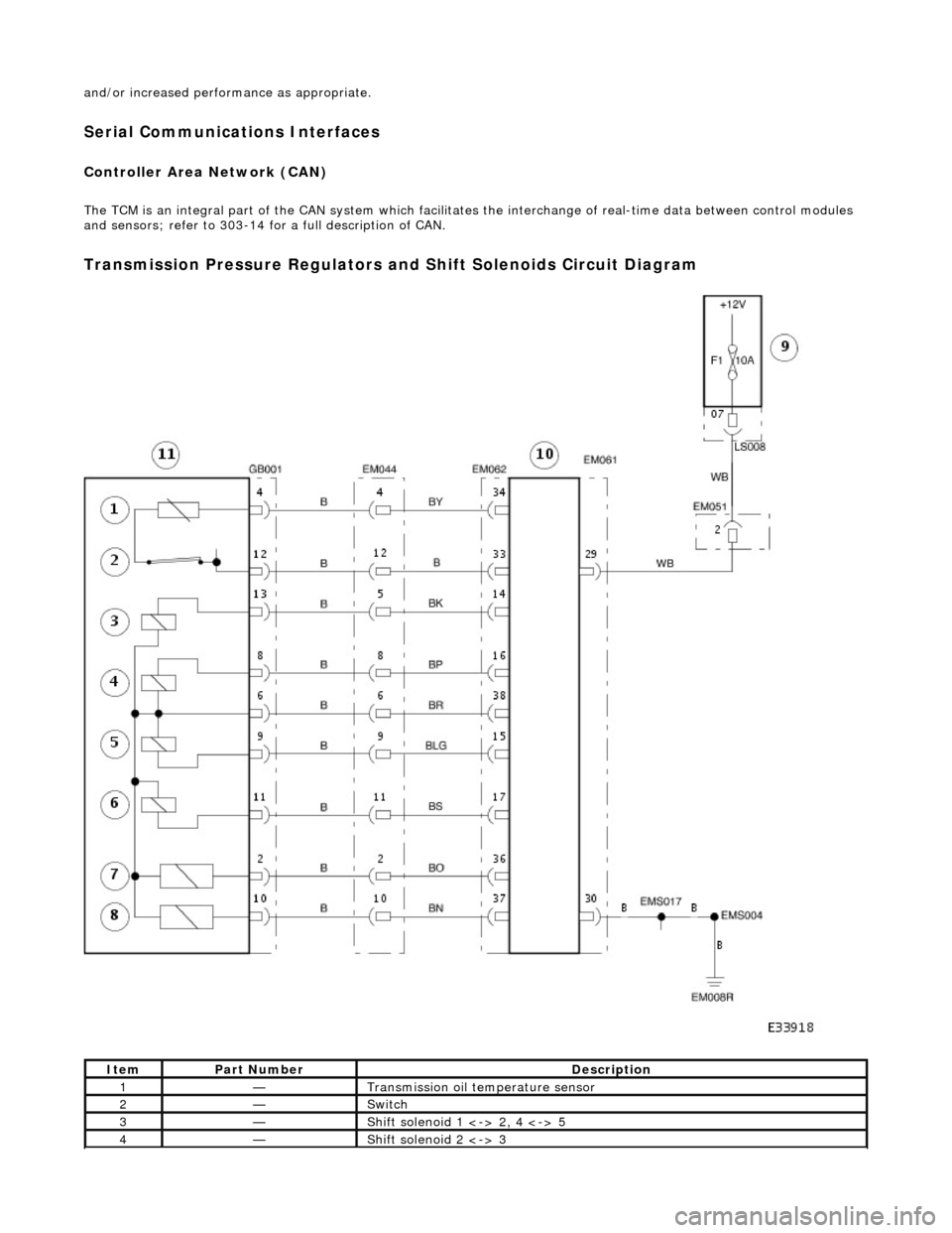
Transmission Pressure Regulators and Shift Solenoids Circuit Diagram
ItemPart NumberDescription
1—Transmission oil temperature sensor
2—Switch
3—Shift solenoid 1 <-> 2, 4 <-> 5
4—Shift solenoid 2 <-> 3
Page 1448 of 2490

Automatic Transmission/Transaxle - 4.0L SC V8 - AJ26 - Transmission
Removal
Removal
Special Tool(s)
Engine support
303-021
Engine lifting brackets
303-536
1. Select N gear position.
2. Disconnect the battery ground lead.
3. Remove the engine covers. Re fer to Operation 12.30.06.
4. Remove the air intake tube, MAFM and air cleaner cover
assembly. Refer to Operation 19.10.30.
5. Disconnect the transmission link lead connector.
1. Release the connector fr om its mounting bracket.
2. Disconnect the multiplug.
6. Remove the EMS harness mounting bracket.
пЃ¬Release the bolt, bracket to cylinder head.
7. Fit engine lifting bracket 307 - 536 at the rear RH.
Page 1458 of 2490

Automatic Transmission/Transaxle - 4.0L SC V8 - AJ26 - Transmission
Installation
Installation
Special Tool(s)
Engine support
303-021
Engine lifting brackets
303-536
1. CAUTION: A new transmission requires a NEW torque
converter.
Installation is the re verse of the removal procedure, noting the
following:
2. Clean all mating faces and relevant parts.
3. Apply lubricant, MOLYCOTE or equivalent to the torque
converter spigot.
4. Fit the screw (lower) securing th e harness link lead heatshield.
Tighten to the specified torque figure.
5. Fit the dipstick lower tube.
пЃ¬Remove the blanking plug and fit a new O-ring seal.
Tighten the bolt to the specified torque figure.