303 JAGUAR X308 1998 2.G Workshop Manual
[x] Cancel search | Manufacturer: JAGUAR, Model Year: 1998, Model line: X308, Model: JAGUAR X308 1998 2.GPages: 2490, PDF Size: 69.81 MB
Page 1162 of 2490
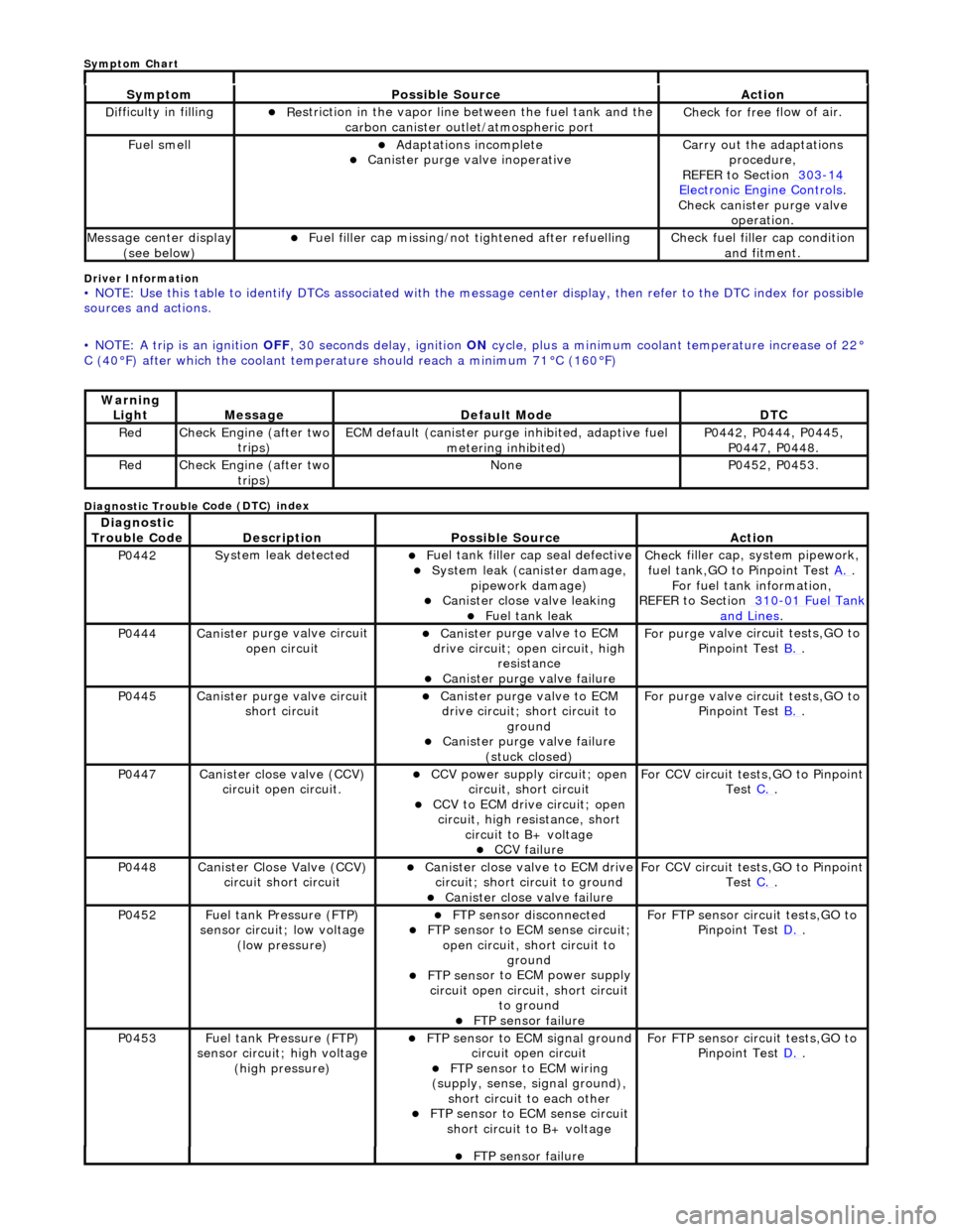
Driver Info
rmation
•
NOTE: Use this table to identify DTCs associated with the me
ssage center display, then refer to the DTC index for possible
sources and actions.
• NOTE: A trip is an ignition OFF, 30 seconds delay, ignition ON cycle, plus a minimum coolant temperature increase of 22°
C (40В°F) after which the coolant temperat ure should reach a minimum 71В°C (160В°F)
Diagnostic Trouble C
ode (DTC) index
Sy
m
ptom
Possib
l
e Source
Acti
o
n
D
i
fficulty in filling
пЃ¬R
e
striction in the vapor line between the fuel tank and the
carbon canister outlet/atmospheric port
Check f or free f
low of air.
F
u
el smell
пЃ¬Adaptat
i
ons incomplete
пЃ¬Cani
st
er purge valve inoperative
Carry
o
ut the adaptations
procedure,
REFER to Section 303
-14 Ele c
tronic Engine Controls
.
Chec k cani
ster purge valve
operation.
M e
ssage center display
(see below)
пЃ¬Fue l
filler cap missing/not
tightened after refuelling
Check fu
el filler cap condition
and fitment.
Warning Li
ght
Mess
age Defaul
t Mode
DT
C
RedCheck Engine (after two
trip
s)
ECM de
fa
ult (canister purge inhibited, adaptive fuel
metering inhibited)
P0442,
P0444, P0445,
P0447, P0448.
Re dCheck Engine (after two
trip
s)
No
neP04 52,
P0453.
Di
agno
stic
Trouble Code
De scr
iption
Possib
l
e Source
Acti
o
n
P0442Sy
st
em leak detected
пЃ¬F
u
el tank filler cap seal defective
пЃ¬Sy
ste
m leak (c
anister damage,
pipework damage)
пЃ¬Cani st
er close valve leaking
пЃ¬F
u
el tank leak
Chec
k fi
ller cap,
system pipework,
fuel tank,GO to Pinpoint Test A.
.
F o
r fuel tank information,
REFER to Section 310
-01 Fu
el Tank
and Lines.
P0444Canist
er purge valve circuit
open circuit
пЃ¬Cani st
er purge valve to ECM
drive circuit; open circuit, high
resistance
пЃ¬Cani st
er purge valve failure
F
or purge
valve circuit tests,GO to
Pinpoint Test B.
.
P0445Canist
er purge valve circuit
short circuit
пЃ¬Cani st
er purge valve to ECM
drive circuit; short circuit to ground
пЃ¬Canist
er purge valve failure
(stuck closed)
F or purge
valve circuit tests,GO to
Pinpoint Test B.
.
P0447Canist
er close valve (CCV)
circuit open circuit.
пЃ¬CCV power su pply ci
rcuit; open
circuit, short circuit
пЃ¬CCV to ECM drive circuit;
open
circuit, high resistance, short circuit to B+ voltage
пЃ¬CCV failure
Fo
r CCV circuit tests,GO to Pinpoint
Test C.
.
P0448Canist
er Close Valve (CCV)
circuit short circuit
пЃ¬Cani st
er close valve to ECM drive
circuit; short circuit to ground
пЃ¬Cani st
er close valve failure
F
o
r CCV circuit tests,GO to Pinpoint
Test C.
.
P0452 Fu
el tank Pressure (FTP)
sensor circuit; low voltage (low pressure)
пЃ¬FTP sen
sor disconnected
пЃ¬FTP sen
sor to ECM sense circuit;
open circuit, short circuit to ground
пЃ¬FTP sens
or to ECM power supply
circuit open circuit, short circuit to ground
пЃ¬FT
P sensor failure
For FT
P se
nsor circuit tests,GO to
Pinpoint Test D.
.
P0453Fu
el tank Pressure (FTP)
sensor circuit; high voltage
(high pressure)
пЃ¬FTP sen
sor to ECM signal ground
circuit open circuit
пЃ¬F T
P sensor to ECM wiring
(supply, sense, signal ground),
short circuit to each other
пЃ¬FTP sen
sor to ECM sense circuit
short circuit to B+ voltage
For FT P se
nsor circuit tests,GO to
Pinpoint Test D.
.
пЃ¬FT
P sensor failure
Sym
ptom Chart
Page 1179 of 2490
пЃ¬generates a signal when th
e dr
ive plate passes the sensor
пЃ¬sen
ds the ECM signals indicating crankshaft position and engine speed
пЃ¬is e
ssential for calculating spark timing
En
gine Coolant Temperature (ECT) Sensor
пЃ¬sen
ds the ECM a signal indicating the temperature of the engine coolant
пЃ¬is a t
emperature dependent resistor with a negative temperature coefficient (resistance changes inversely with
respect to temperature) and is constantly monitored by the ECM
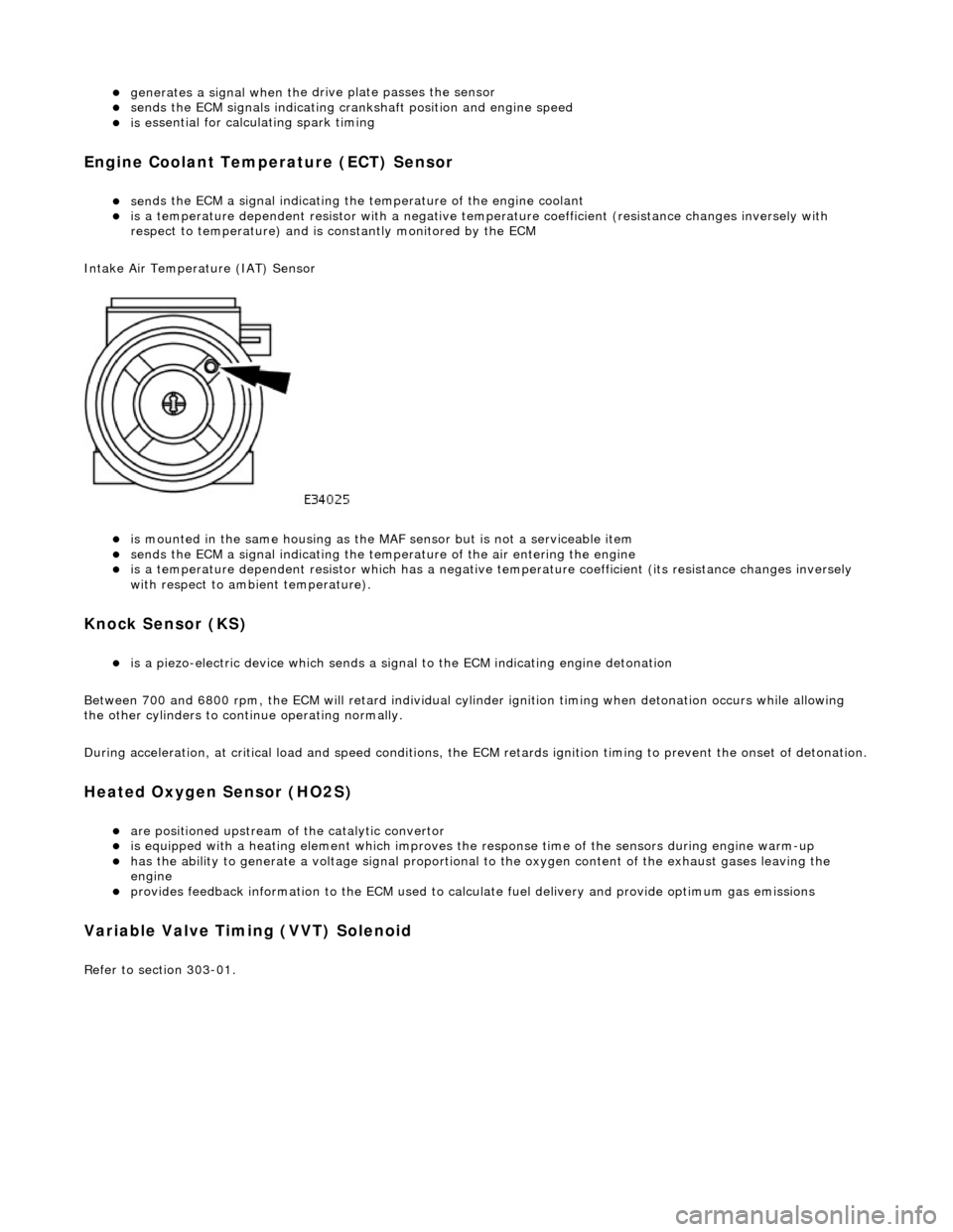
Intake Air Temperature (IAT) Sensor
пЃ¬is m
ounted in the same housing as the MA
F sensor but is not a serviceable item
пЃ¬sen
ds the ECM a signal indicating the temperature of the air entering the engine
пЃ¬is a t
emperature dependent resistor which has a negative
temperature coefficient (its resistance changes inversely
with respect to ambient temperature).
Knock S
ensor (KS)
пЃ¬is a pi
ezo-electric device which sends a signal
to the ECM indicating engine detonation
Between 700 and 6800 rpm, the ECM will retard individual cylinder ignition timing when detonation occurs while allowing
the other cylinders to continue operating normally.
During acceleration, at critical load and speed conditions, the ECM retards ignition timing to prevent the onset of detonation.
H
eated Oxygen Sensor (HO2S)
пЃ¬are
positioned upstream of the catalytic convertor
пЃ¬is equipped with
a heating element wh
ich improves the response time of the sensors during engine warm-up
пЃ¬h
as the ability to generate a voltage signal proportional to the oxygen content of the exhaust gases leaving the
engine
пЃ¬pr
ovides feedback information to the ECM used to calc
ulate fuel delivery and provide optimum gas emissions
Variable V
alve Timing (VVT) Solenoid
R
efer to section 303-01.
Page 1190 of 2490
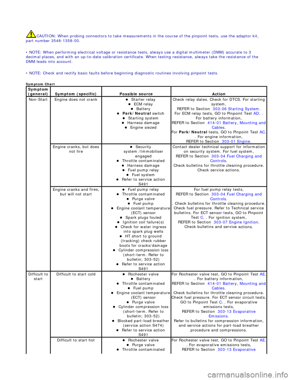
CAUTIO
N: When probing connectors to take
measurements in the course of the pinpoint tests, use the adaptor kit,
part number 3548-1358-00.
• NOTE: When performing electrical voltag e or resistance tests, always use a digital multimeter (DMM) accurate to 3
decimal places, and with an up-t o-date calibration certificate. When testing resistance, always take the resistance of the
DMM leads into account.
• NOTE: Check and rectify basic faults before beginning diagnostic ro utines involving pinpoint tests.
Sym
ptom Chart
Sym
ptom
(general)
S y
mptom (specific)
Possib
l
e source
Acti
o
n
No
n
-Start
Engine
does not cran
k
пЃ¬Starter relay пЃ¬ECM relay пЃ¬Batt
ery пЃ¬Park
/Neutral
switch
пЃ¬Starting system
пЃ¬Harness damage
пЃ¬Engine s
iezed
Check r
e
lay dates. Check
for DTCS. For starting
system,
REFER to Section 303
-06 Sta r
ting System
.
F or ECM
relay tests, GO to Pinpoint Test
AD.
.
F o
r battery information,
REFER to Section 414
-0 1
Battery, Mounting and
Cables.
Fo r
Park/Neutral tests, GO to Pinpoint Test AC.
. Fo
r engine information,
REFER to Section 303
-01 En
gine
.
Engine cranks, but does
not fireпЃ¬Security
syst
em /Immobiliser
engaged
пЃ¬Thr o
ttle contaminated
пЃ¬Harness damage
пЃ¬Fu
el pump relay
пЃ¬Fue
l
system
пЃ¬R
e
fer to service action
S491
Contact dealer techni
cal
support for information
on security system. For fuel system,
REFER to Section 303
-0 4
Fuel Charging and
Controls.
Check bull etins for throttl
e cleaning procedure.
Check service actions.
Engine cranks an d
fires,
but will not start
пЃ¬F u
el pump relay
пЃ¬Thr
o
ttle contaminated
пЃ¬Purge
val
ve
пЃ¬Fue
l
pump
пЃ¬Engine coolan
t
temperature
(ECT) sensor
пЃ¬Spark plugs
fouled
пЃ¬Ignition coil
fail
ure(s)
пЃ¬Check f
o
r water ingress
into spark plug wells
пЃ¬HT sh o
rt to ground
(tracking) check rubber
boots for cracks/damage
пЃ¬Cyli
nder compression loss
(short-term. Refer to bulletin; 303-52)
пЃ¬Re
fer to service action
S491
Fo
r fuel pump relay tests,
REFER to Section 303
-0 4
Fuel Charging and
Controls.
. Check bulletins for throttl
e cleaning procedure.
Check fuel pressure. Refe r to Technical service
bulletins. For ECT sensor tests, GO to Pinpoint Test C.
. Fo
r ignition system,
REFER to Section 303
-07 En
gine Ignition
.
Check bulletins an d service a
ctions.
Di
f
ficult to
start
D iff
icult to start cold
пЃ¬Roc
h
ester valve
пЃ¬Batt
ery пЃ¬Thro
ttle contaminated
пЃ¬Fue
l
pump
пЃ¬Engine coolan
t
temperature
(ECT) sensor
пЃ¬Purge val
ve
пЃ¬Cyl
i
nder compression loss
(short-term. Refer to bulletin; 303-52)
пЃ¬Blocked part-load breather (s
ervice action S474)
пЃ¬R
e
fer to service action
S491
For R
ochester valv
e test, GO to Pinpoint Test AE.
. Fo
r battery information,
REFER to Section 414
-0 1
Battery, Mounting and
Cables.
Check bull etins for throttl
e cleaning procedure.
Check fuel pressure. For ECT sensor circuit tests,
GO to Pinpoint Test C.
. F
or evaporative
emissions tests,
REFER to Section 303
-1 3
Evaporative
Emiss
i
ons
.
R e
fer to bulletins for co
mpression information,
and service actions for part-load breather procedure and compressions.
Diff
icult to start hot
пЃ¬Roc
h
ester valve
пЃ¬Purge
val
ve
пЃ¬Thr
o
ttle contaminated
F
or R
ochester valv
e test, GO to Pinpoint Test AE.
. F
or evaporative emissions tests,
REFER to Section 303
-1 3
Evaporative
Page 1191 of 2490
пЃ¬Fue
l pump
пЃ¬Engine coolan
t temperature
(ECT) sensor
пЃ¬Blocked part-load breather (
service action S474)
пЃ¬Injec
tor leak
Emiss
ions
.
Check bull
etins for throttle cleaning procedure.
Check fuel pressure. For ECT sensor circuit tests,
GO to Pinpoint Test C.
. Refer to Servi
ce action
S474 for part-load breather procedure. For
injector leak test, Refer to technical service bulletin 303-39.
D
ifficult to start after hot
soak (vehicle standing
after engine has reached operating temperature)
пЃ¬Roc
hester valve
пЃ¬Thr
ottle contaminated
пЃ¬Purge
valve
пЃ¬Fue
l pump
пЃ¬Engine coolan
t temperature
(ECT) sensor
пЃ¬Blocked part-load breather (
service action S474)
пЃ¬Injec
tor leak
Engine cranks too
fa
st/slow
пЃ¬Batt
ery
пЃ¬Starter relay пЃ¬Harness пЃ¬Cyl
inder compression loss
(NA short term only. Refer to technical service bulletin; 303-39)
пЃ¬R
efer to service action
S491
F
or battery information,
REFER to Section 414
-0
1 Battery, Mounting and
Cables.
F
or starting system.
REFER to Section 303
-06 Sta
rting System
.
R
efer to technical servic
e bulletins and service
actions.
Engine
stalls
Engine st
alls soon after
start
пЃ¬F
uel pump relay
пЃ¬ECM relay пЃ¬Thr
ottle contaminated
пЃ¬CMP/CKP sen
sor
synchronization malfunction
пЃ¬Harness пЃ¬Fue
l pump
пЃ¬MAF
sensor malfunction
пЃ¬Engine coolan
t temperature
(ECT) sensor
пЃ¬Fue
l lines
пЃ¬Air leakage
пЃ¬F
uel pressure regulator
Check r
elay dates. Chec
k for DTCs. For fuel
pump relay tests,
REFER to Section 303
-0
4 Fuel Charging and
Controls.
F
or ECM relay tests, GO to Pinpoint Test
AD.
.
Check bull
etins for throttle cleaning procedure.
For CMP sensor circuit test s, GO to Pinpoint Test
C.
, for
CKP sensor circuit tests, GO to Pinpoint
Test N.
. Check fuel
pressure. For MAF sensor
circuit tests, GO to Pinpoint Test A.
. For EC
T
sensor tests, GO to Pinpoint Test C.
. F
or fuel
system,
REFER to Section 303
-0
4 Fuel Charging and
Controls.
and
REF
ER to Section 310
-0
1 Fuel Tank and Lines
. F
or intake system information,
REFER to Section 303
-1
2 Intake Air Distribution
and F
iltering
.
Engine
stalls on overrun
пЃ¬Thr
ottle contaminated
пЃ¬ECM relay пЃ¬F
uel pump relay
пЃ¬CMP/CKP sen
sor
synchronization malfunction
Check bull
etins for throttle cleaning procedure.
Check relay dates. For ECM relay tests, GO to Pinpoint Test AD.
. F
or fuel pump relay tests,
REFER to Section 303
-0
4 Fuel Charging and
Controls.
F
or CMP sensor circuit test
s, GO to Pinpoint Test
O.
, for
CKP sensor circuit tests, GO to Pinpoint
Test N.
.
E
ngine stalls at steady
speed, with or without cruise enabled
пЃ¬Thr
ottle contaminated
пЃ¬ECM relay пЃ¬F
uel pump relay
пЃ¬CMP/CKP sen
sor
synchronization malfunction
пЃ¬Harness пЃ¬Blocked part-load breather
(
service action S474)
Check bull
etins for throttle cleaning procedure.
Check relay dates. For EC M relay circuit tests,GO
to Pinpoint Test AD.
. F
or fuel pump relay circuit
tests,
REFER to Section 303
-0
4 Fuel Charging and
Controls.
F
or CMP sensor circuit test
s,GO to Pinpoint Test
O.
, for
CKP sensor circuit tests,GO to Pinpoint
Test N.
. Che
ck service actions.
Engine st
alls when
maneuvering
пЃ¬ECM relay пЃ¬F
uel pump relay
пЃ¬CMP/CKP sen
sor
synchronization malfunction
Check r
elay dates. For EC
M relay circuit tests,GO
to Pinpoint Test AD.
. F
or fuel pump relay circuit
tests,
REFER to Section 303
-0
4 Fuel Charging and
Controls.
F
or CMP sensor circuit test
s,GO to Pinpoint Test
O.
, for
CKP sensor circuit tests,GO to Pinpoint
Test N.
.
Page 1192 of 2490
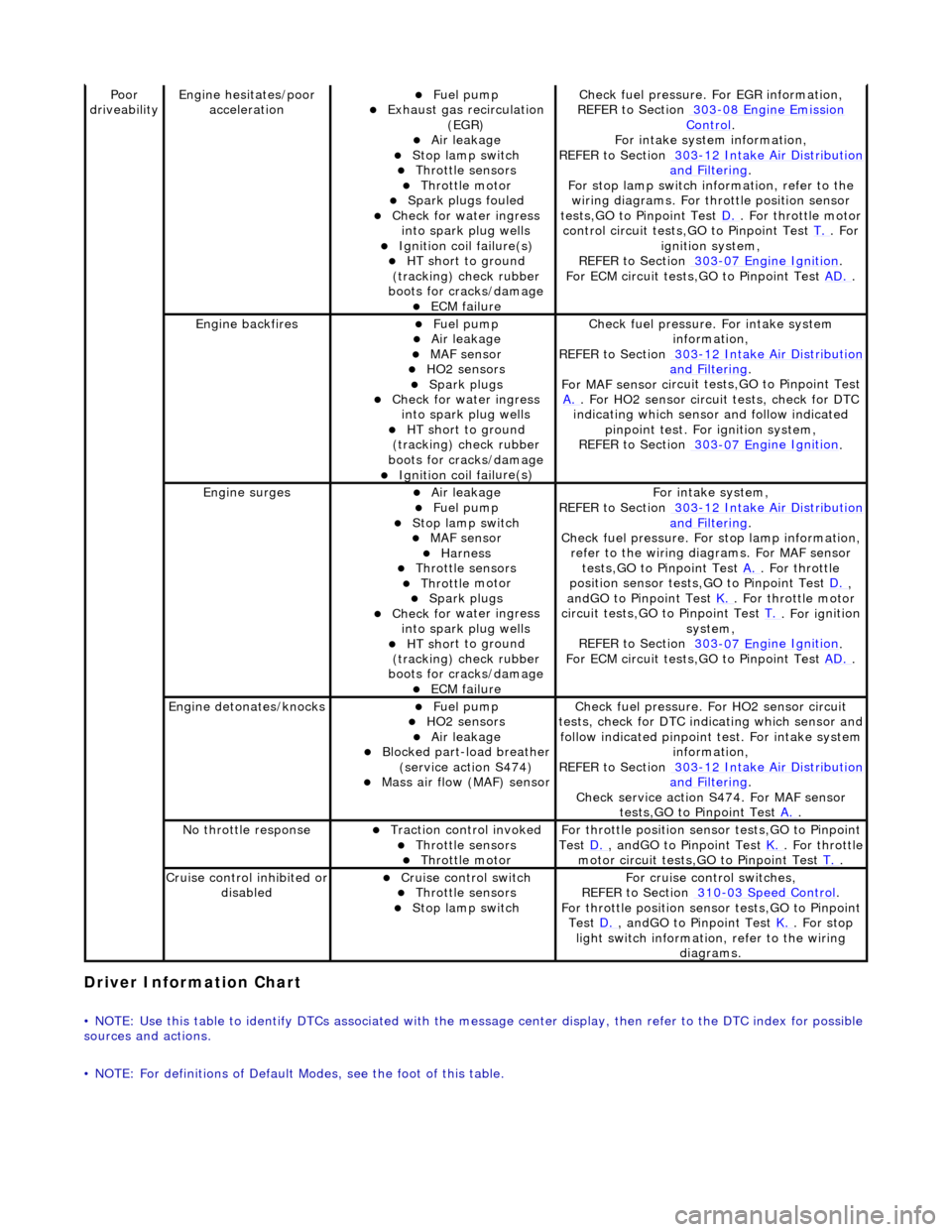
Driver Information
Chart
•
NOTE: Use this table to identify DTCs associated with the me
ssage center display, then refer to the DTC index for possible
sources and actions.
• NOTE: For definitions of Default Modes, see the foot of this table.
Poor
dr iveabilityEngine h e
sitates/poor
acceleration
пЃ¬Fue l
pump
пЃ¬Exhaus
t gas
recirculation
(EGR)
пЃ¬Air leakage пЃ¬Stop lamp swi t
ch
пЃ¬Throttl
e
sensors
пЃ¬Throttl
e
motor
пЃ¬Spark
plugs
fouled
пЃ¬Check f
o
r water ingress
into spark plug wells
пЃ¬Ignition coil fail
ure(s)
пЃ¬HT sh
o
rt to ground
(tracking) check rubber
boots for cracks/damage
пЃ¬ECM failu r
e
Check f
u
el pressure. For EGR information,
REFER to Section 303
-08 En gin
e Emission
Control.
F or i
ntake system information,
REFER to Section 303
-1 2
Intake Air Distribution
and F
ilt
ering
.
F or stop l
amp switch in
formation, refer to the
wiring diagrams. For throttle position sensor
tests,GO to Pinpoint Test D.
. Fo
r throttle motor
control circuit tests,GO to Pinpoint Test T.
. For
igni t
ion system,
REFER to Section 303
-07 En
gine Ignition
.
F or ECM
circuit tests,GO to Pinpoint Test
AD.
.
Engine backfiresпЃ¬Fuel
pump
пЃ¬Air leakage пЃ¬MAF se
nsor
пЃ¬HO2 sensors
пЃ¬Spark plugs пЃ¬Check fo
r water ingress
into spark plug wells
пЃ¬HT sh o
rt to ground
(tracking) check rubber
boots for cracks/damage
пЃ¬Ignition coil fail
ure(s)
Chec
k fu
el pressure. For intake system
information,
REFER to Section 303
-12
Intake Air Distribution
and Filt
ering
.
F or MAF sensor ci
rcuit test
s,GO to Pinpoint Test
A.
. F or HO2 sensor
circui
t tests, check for DTC
indicating which sensor and follow indicated pinpoint test. For ignition system,
REFER to Section 303
-07 En
gine Ignition
.
Engine
s
urges
пЃ¬Air leakage
пЃ¬Fuel
pump
пЃ¬Stop lamp swit
ch
пЃ¬MAF s
e
nsor
пЃ¬Harness пЃ¬Throttl
e
sensors
пЃ¬Throttl
e
motor
пЃ¬Spark plugs
пЃ¬Check fo
r water ingress
into spark plug wells
пЃ¬HT sh o
rt to ground
(tracking) check rubber
boots for cracks/damage
пЃ¬ECM failu r
e
Fo
r
intake system,
REFER to Section 303
-1 2
Intake Air Distribution
and Filt
ering
.
Check fu
el pressure. For
stop lamp information,
refer to the wiring diagrams. For MAF sensor tests,GO to Pinpoint Test A.
. Fo
r throttle
position sensor tests,GO to Pinpoint Test D.
,
a n
dGO to Pinpoint Test
K.
. Fo
r throttle motor
circuit tests,GO to Pinpoint Test T.
. For ig
nition
system,
REFER to Section 303
-07 En
gine Ignition
.
F or ECM
circuit tests,GO to Pinpoint Test
AD.
.
Engine detonates/k
nocks
пЃ¬Fue
l
pump
пЃ¬HO2 sensors
пЃ¬Air leakage пЃ¬Blocked part-load breather
(s
ervice action S474)
пЃ¬Mass ai
r fl
ow (MAF) sensor
Chec
k fu
el pressure. Fo
r HO2 sensor circuit
tests, check for DTC indicating which sensor and
follow indicated pinpoint test. For intake system
information,
REFER to Section 303
-1 2
Intake Air Distribution
and Filt
ering
.
Check service action S474
. For MAF sensor
tests,GO to Pinpoint Test A.
.
No t
hrottle response
пЃ¬Traction contr
o
l invoked
пЃ¬Throttl
e
sensors
пЃ¬Throttl
e
motor
Fo
r th
rottle position sensor tests,GO to Pinpoint
Test D.
, andG O to Pinpoint
Test
K.
. Fo
r throttle
motor circuit tests,GO to Pinpoint Test T.
.
Cru i
se control inhibited or
disabled
пЃ¬Cru i
se control switch
пЃ¬Throttle
sensors
пЃ¬Stop lamp swit
ch
For cru
i
se control switches,
REFER to Section 310
-03
Speed Control
.
For th
rottle position sensor tests,GO to Pinpoint
Test D.
, andG O to Pinpoint
Test
K.
. For s t
op
light switch information, refer to the wiring diagrams.
Page 1193 of 2490
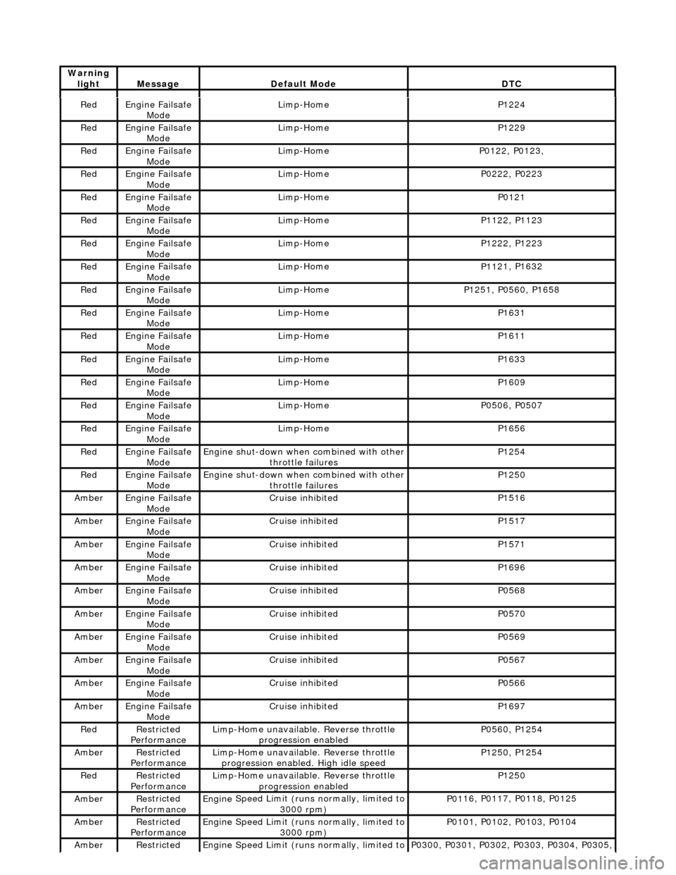
Re
d
Engine
Failsafe
Mode
Lim
p-Home
P1224
Re
d
Engine
Failsafe
Mode
Lim
p-Home
P1229
Re
d
Engine
Failsafe
Mode
Lim
p-Home
P01
22, P0123,
Re
d
Engine
Failsafe
Mode
Lim
p-Home
P02
22, P0223
Re
d
Engine
Failsafe
Mode
Lim
p-Home
P0121
Re
d
Engine
Failsafe
Mode
Lim
p-Home
P11
22, P1123
Re
d
Engine
Failsafe
Mode
Lim
p-Home
P12
22, P1223
Re
d
Engine
Failsafe
Mode
Lim
p-Home
P11
21, P1632
Re
d
Engine
Failsafe
Mode
Lim
p-Home
P12
51, P0560, P1658
Re
d
Engine
Failsafe
Mode
Lim
p-Home
P1631
Re
d
Engine
Failsafe
Mode
Lim
p-Home
P1611
Re
d
Engine
Failsafe
Mode
Lim
p-Home
P1633
Re
d
Engine
Failsafe
Mode
Lim
p-Home
P1609
Re
d
Engine
Failsafe
Mode
Lim
p-Home
P05
06, P0507
Re
d
Engine
Failsafe
Mode
Lim
p-Home
P1656
Re
d
Engine
Failsafe
Mode
Engine
shut-down when combined with other
throttle failures
P1254
Re
d
Engine
Failsafe
Mode
Engine
shut-down when combined with other
throttle failures
P1250
Ambe
r
Engine
Failsafe
Mode
Cruis
e inhibited
P1516
Ambe
r
Engine
Failsafe
Mode
Cruis
e inhibited
P1517
Ambe
r
Engine
Failsafe
Mode
Cruis
e inhibited
P1571
Ambe
r
Engine
Failsafe
Mode
Cruis
e inhibited
P1696
Ambe
r
Engine
Failsafe
Mode
Cruis
e inhibited
P0568
Ambe
r
Engine
Failsafe
Mode
Cruis
e inhibited
P0570
Ambe
r
Engine
Failsafe
Mode
Cruis
e inhibited
P0569
Ambe
r
Engine
Failsafe
Mode
Cruis
e inhibited
P0567
Ambe
r
Engine
Failsafe
Mode
Cruis
e inhibited
P0566
Ambe
r
Engine
Failsafe
Mode
Cruis
e inhibited
P1697
Re
d
Re
stricted
Performance
Li
mp-Home unavailable. Reverse throttle
progression enabled
P05
60, P1254
Ambe
r
Re
stricted
Performance
Li
mp-Home unavailable. Reverse throttle
progression enabled. High idle speed
P12
50, P1254
Re
d
Re
stricted
Performance
Li
mp-Home unavailable. Reverse throttle
progression enabled
P1250
Ambe
r
Re
stricted
Performance
Engine
Speed Limit (runs normally, limited to
3000 rpm)
P01
16, P0117, P0118, P0125
Ambe
r
Re
stricted
Performance
Engine
Speed Limit (runs normally, limited to
3000 rpm)
P01
01, P0102, P0103, P0104
Ambe
r
Re
stricted
Engine
Speed Limit (runs normally, limited to
P03
00, P0301, P0302, P0303, P0304, P0305,
Warning
lightMess
age
De
fault Mode
DT
C
Page 1195 of 2490
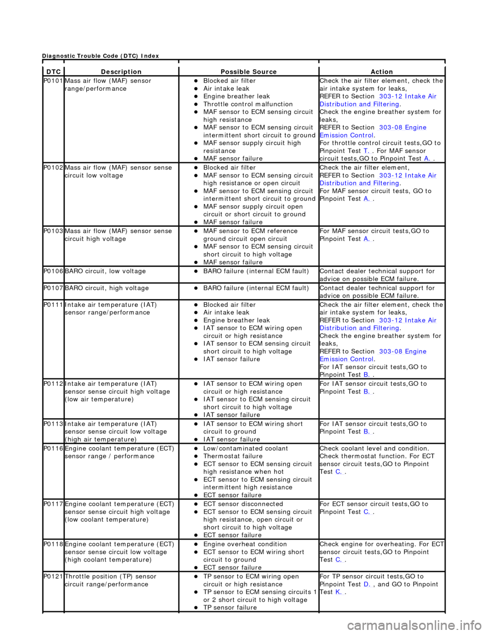
DT
C
De
scription
Possib
le Source
Acti
on
P0101Mass ai
r flow (MAF) sensor
range/performance
пЃ¬Bl
ocked air filter
пЃ¬Air
intake leak
пЃ¬Engine
breather leak
пЃ¬Throttl
e control malfunction
пЃ¬MAF
sensor to ECM sensing circuit
high resistance
пЃ¬MAF
sensor to ECM sensing circuit
intermittent short circuit to ground
пЃ¬MAF
sensor supply circuit high
resistance
пЃ¬MAF
sensor failure
Chec
k the air filter element, check the
air intake system for leaks,
REFER to Section 303
-1
2 Intake Air
Distribu
tion and Filtering
.
Chec
k the engine breather system for
leaks,
REFER to Section 303
-08
Engine
Emissi
on Control
.
F
or throttle control circuit tests,GO to
Pinpoint Test T.
. Fo
r MAF sensor
circuit tests,GO to Pinpoint Test A.
.
P0102Mass ai
r flow (MAF) sensor sense
circuit low voltage
пЃ¬Bl
ocked air filter
пЃ¬MAF
sensor to ECM sensing circuit
high resistance or open circuit
пЃ¬MAF
sensor to ECM sensing circuit
intermittent short circuit to ground
пЃ¬MAF
sensor supply circuit open
circuit or short circuit to ground
пЃ¬MAF
sensor failure
Chec
k the air filter element,
REFER to Section 303
-1
2 Intake Air
Distribu
tion and Filtering
.
For MAF
sensor circuit tests, GO to
Pinpoint Test A.
.
P0103Mass ai
r flow (MAF) sensor sense
circuit high voltage
пЃ¬MAF
sensor to ECM reference
ground circuit open circuit
пЃ¬MAF
sensor to ECM sensing circuit
short circuit to high voltage
пЃ¬MAF sensor
failure
For MAF
sensor circuit tests,GO to
Pinpoint Test A.
.
P0106BARO ci
rcuit, low voltage
пЃ¬BARO f
ailure (internal ECM fault)
Contact deal
er technical support for
advice on possible ECM failure.
P0107BARO ci
rcuit, high voltage
пЃ¬BARO f
ailure (internal ECM fault)
Contact deal
er technical support for
advice on possible ECM failure.
P0111In
take air temperature (IAT)
sensor range/performance
пЃ¬Bl
ocked air filter
пЃ¬Air
intake leak
пЃ¬Engine
breather leak
пЃ¬IAT sensor to
ECM wiring open
circuit or high resistance
пЃ¬IAT se
nsor to ECM sensing circuit
short circuit to high voltage
пЃ¬IAT sensor fail
ure
Chec
k the air filter element, check the
air intake system for leaks,
REFER to Section 303
-1
2 Intake Air
Distribu
tion and Filtering
.
Chec
k the engine breather system for
leaks,
REFER to Section 303
-08
Engine
Emissi
on Control
.
F
or IAT sensor circuit tests,GO to
Pinpoint Test B.
.
P0112In
take air temperature (IAT)
sensor sense circuit high voltage
(low air temperature)
пЃ¬IAT sensor to
ECM wiring open
circuit or high resistance
пЃ¬IAT se
nsor to ECM sensing circuit
short circuit to high voltage
пЃ¬IAT sensor fail
ure
F
or IAT sensor circuit tests,GO to
Pinpoint Test B.
.
P0113In
take air temperature (IAT)
sensor sense circuit low voltage
(high air temperature)
пЃ¬IAT sensor to
ECM wiring short
circuit to ground
пЃ¬IAT sensor fail
ure
F
or IAT sensor circuit tests,GO to
Pinpoint Test B.
.
P0116E
ngine coolant temperature (ECT)
sensor range / performance
пЃ¬Low/contaminated coolant пЃ¬Therm
ostat failure
пЃ¬ECT se
nsor to ECM sensing circuit
high resistance when hot
пЃ¬ECT se
nsor to ECM sensing circuit
intermittent high resistance
пЃ¬ECT sensor
failure
Che
ck coolant level and condition.
Check thermostat function. For ECT
sensor circuit tests,GO to Pinpoint
Test C.
.
P0117E
ngine coolant temperature (ECT)
sensor sense circuit high voltage
(low coolant temperature)
пЃ¬ECT se
nsor disconnected
пЃ¬ECT se
nsor to ECM sensing circuit
high resistance, open circuit or
short circuit to high voltage
пЃ¬ECT sensor
failure
F
or ECT sensor circuit tests,GO to
Pinpoint Test C.
.
P0118E
ngine coolant temperature (ECT)
sensor sense circuit low voltage
(high coolant temperature)
пЃ¬Engine
overheat condition
пЃ¬ECT se
nsor to ECM wiring short
circuit to ground
пЃ¬ECT sensor
failure
Chec
k engine for overheating. For ECT
sensor circuit tests,GO to Pinpoint
Test C.
.
P0121Thro
ttle position (TP) sensor
circuit rang e/performance
пЃ¬TP sensor
to ECM wiring open
circuit or high resistance
пЃ¬TP se
nsor to ECM sensing circuits 1
or 2 short circuit to high voltage
пЃ¬TP sensor
failure
F
or TP sensor circ
uit tests,GO to
Pinpoint Test D.
, and G
O to Pinpoint
Test K.
.
D
iagnostic Trouble Code (DTC) Index
Page 1196 of 2490
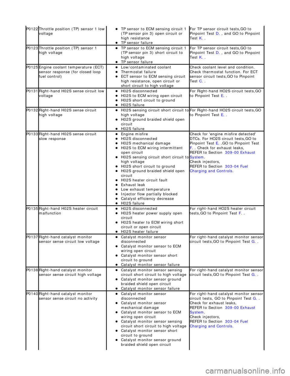
P0122Throttle
position (TP) sensor 1 low
voltage
пЃ¬TP se ns
or to ECM sensing circuit 1
(TP sensor pin 3) open circuit or
high resistance
пЃ¬TP sensor fail
ure
F
o
r TP sensor circ
uit tests,GO to
Pinpoint Test D.
, and GO
to Pinpoint
Test K.
.
P0123Throttl e
position (TP) sensor 1
high voltage
пЃ¬TP se ns
or to ECM sensing circuit 1
(TP sensor pin 3) short circuit to
high voltage
пЃ¬TP sensor fail
ure
F
o
r TP sensor circ
uit tests,GO to
Pinpoint Test D.
, and GO
to Pinpoint
Test K.
.
P0125En
gine coolant temperature (ECT)
sensor response (for closed loop
fuel control)
пЃ¬Low/contaminated coolant пЃ¬Therm o
stat failure
пЃ¬ECT se
ns
or to ECM sensing circuit
high resistance, open circuit or
short circuit to high voltage
Che c
k coolant level and condition.
Check thermostat function. For ECT
sensor circuit tests,GO to Pinpoint
Test C.
.
P0131Right -
hand H02S sense circuit low
voltage
пЃ¬H02 S
disconnected
пЃ¬H0
2S to
ECM wiring open circuit
пЃ¬H0
2S short ci
rcuit to ground
пЃ¬H0
2S fail
ure
F
or R
ight-hand HO2S circuit tests,GO
to Pinpoint Test E.
.
P0132Right-
hand H02S sense circuit
high voltage
пЃ¬H02 S
sensing circuit short circuit to
high voltage
пЃ¬H0 2S groun
d braided shield open
circuit
пЃ¬H0 2S fail
ure
F
or R
ight-hand HO2S circuit tests,GO
to Pinpoint Test E.
.
P0133Right-
hand H02S sense circuit
slow response
пЃ¬Engine m
isfire
пЃ¬H02
S
disconnected
пЃ¬H0
2S mechanical damage
пЃ¬H0
2S to
ECM wiring intermittent
open circuit
пЃ¬H02 S
sensing circuit short circuit to
high voltage
пЃ¬H02S short ci
rcuit to ground
пЃ¬H02S groun
d braided shield open
circuit
пЃ¬H0 2S heater circuit faul
t
пЃ¬Exhaus
t leak
пЃ¬Low e
x
haust temperature
пЃ¬Injector fl
ow parti
ally blocked
пЃ¬Catal
y
st efficiency decrease
пЃ¬H0
2S fail
ure
Chec
k for 'en
gine misfire detected'
DTCs. For HO2S circuit tests,GO to
Pinpoint Test E.
.G
O to Pinpoint Test
F.
. Check for exhaust leaks,
REF
ER to Section 309
-00
Ex
haust
Sy
ste
m
.
Chec k inje
ctors,
REFER to Section 303
-04 Fu
el
Charging and Cont
rols
.
P0135Right
-
hand H02S heater circuit
malfunction
пЃ¬H02 S
disconnected
пЃ¬H0
2S h
eater power supply open
circuit
пЃ¬H0 2S heater to ECM wi
ring short
circuit or open circuit
пЃ¬H0 2S heater fai
lure
F
o
r right-hand HO2S heater circuit
tests,GO to Pinpoint Test F.
.
P0137Right-
hand catalyst monitor
sensor sense circuit low voltage
пЃ¬Catal y
st monitor sensor
disconnected
пЃ¬Catal y
st monitor sensor to ECM
wiring open circuit
пЃ¬Catal y
st monitor sensor short
circuit to ground
пЃ¬Cat a
lyst monitor sensor failure
F
or ri
ght-hand catalyst monitor sensor
circuit tests,GO to Pinpoint Test G.
.
P0138Right -
hand catalyst monitor
sensor sense circuit high voltage
пЃ¬Catal y
st monitor sensor sensing
circuit short circuit to high voltage
пЃ¬Catalyst
monitor sensor ground
braided shield open circuit
пЃ¬Cata
lyst monitor sensor failure
F
or ri
ght-hand catalyst monitor sensor
circuit tests,GO to Pinpoint Test G.
.
P0140Right -
hand catalyst monitor
sensor sense circuit no activity
пЃ¬Catal y
st monitor sensor
disconnected
пЃ¬Catal y
st monitor sensor
mechanical damage
пЃ¬Catal y
st monitor sensor to ECM
wiring open circuit
пЃ¬Catal y
st monitor sensor sensing
circuit short circuit to high voltage
пЃ¬Cataly
st monitor sensor short
circuit to ground
пЃ¬Catalyst
monitor sensor ground
braided shield open circuit
F or ri
ght-hand catalyst monitor sensor
circuit tests, GO to Pinpoint Test G.
.
Check f o
r exhaust leaks,
REFER to Section 309
-00 Ex
haust
Sy
ste
m
.
Chec k inje
ctors,
REFER to Section 303
-04 Fu
el
Charging and Con
t
rols
.
Page 1197 of 2490

пЃ¬Exhaus
t leak
пЃ¬Low e
xhaust temperature
пЃ¬Cat
alyst monitor sensor failure
P0151Le
ft-hand H02S sense circuit low
voltage
пЃ¬H02
S disconnected
пЃ¬H0
2S to ECM wiring open circuit
пЃ¬H0
2S short circuit to ground
пЃ¬H0
2S failure
F
or left-hand HO2S circuit tests, GO
to Pinpoint Test H.
.
P0152Le
ft-hand H02S sense circuit high
voltage
пЃ¬H02
S sensing circuit short circuit to
high voltage
пЃ¬H0
2S ground braided shield open
circuit
пЃ¬H0
2S failure
F
or left-hand HO2S circuit tests,GO to
Pinpoint Test H.
.
P0153Le
ft-hand H02S sense circuit slow
response
пЃ¬Engine
misfire
пЃ¬H02
S disconnected
пЃ¬H0
2S mechanical damage
пЃ¬H0
2S to ECM wiring intermittent
open circuit
пЃ¬H02
S sensing circuit short circuit to
high voltage
пЃ¬H0
2S short circuit to ground
пЃ¬H0
2S ground braided shield open
circuit
пЃ¬H0
2S heater circuit fault
пЃ¬Exhaus
t leak
пЃ¬Low e
xhaust temperature
пЃ¬Injector fl
ow partially blocked
пЃ¬Catal
yst efficiency decrease
пЃ¬H0
2S failure
Chec
k for 'engine misfire detected'
DTCs. For HO2S circ uit tests, GO to
Pinpoint Test H.
. Check for exhaust
leak
s,
REFER to Section 309
-00
Exhaust
Sy
stem
.
Chec
k injectors,
REFER to Section 303
-04
Fuel
Charging and Con
trols
.
P0155Left-hand H02S heater
circuit
malfunction
пЃ¬H02
S disconnected
пЃ¬H0
2S heater power supply open
circuit
пЃ¬H0
2S heater to ECM wiring short
circuit or open circuit
пЃ¬H0
2S heater failure
F
or left-hand HO2S heater circuit
tests,GO to Pinpoint Test I.
.
P0157Le
ft-hand catalyst monitor sensor
sense circuit low voltage
пЃ¬Catal
yst monitor sensor
disconnected
пЃ¬Catal
yst monitor sensor to ECM
wiring open circuit
пЃ¬Catal
yst monitor sensor short
circuit to ground
пЃ¬Cat
alyst monitor sensor failure
F
or left-hand catalyst monitor sensor
circuit tests,GO to Pinpoint Test J.
.
P0158Le
ft-hand catalyst monitor sensor
sense circuit high voltage
пЃ¬Catal
yst monitor sensor sensing
circuit short circuit to high voltage
пЃ¬Catalyst
monitor sensor ground
braided shield open circuit
пЃ¬Cat
alyst monitor sensor failure
F
or left-hand catalyst monitor sensor
circuit tests,GO to Pinpoint Test J.
.
P0160Le
ft-hand catalyst monitor sensor
sense circuit no activity
пЃ¬Catal
yst monitor sensor
disconnected
пЃ¬Catal
yst monitor sensor
mechanical damage
пЃ¬Catal
yst monitor sensor to ECM
wiring open circuit
пЃ¬Catal
yst monitor sensor sensing
circuit short circuit to high voltage
пЃ¬Catal
yst monitor sensor short
circuit to ground
пЃ¬Catalyst
monitor sensor ground
braided shield open circuit
пЃ¬Exhaus
t leak
пЃ¬Low e
xhaust temperature
пЃ¬Cat
alyst monitor sensor failure
F
or left-hand catalyst monitor sensor
circuit tests,GO to Pinpoint Test J.
.
Check f
or exhaust leaks,
REFER to Section 309
-00
Exhaust
Sy
stem
.
P0171Right
-hand cylinders combustion
too lean
пЃ¬Air
intake leak between MAF senso
r and th
rottle
пЃ¬F
uel filter system blockage
пЃ¬F
uel injector blockage
пЃ¬F
uel pressure regulator failure (low
fuel pressure)
пЃ¬Low f
uel pump output
Check ai
r intake system for leaks,
REFER to Section 303
-1
2 Intake Air
Distribu
tion and Filtering
.
Check the fuel fi
lter,
REFER to Section 310
-01
Fuel Tank
and Lines.
Chec
k the fuel injectors and fuel
Page 1198 of 2490

пЃ¬H02S harness wiri
ng fault
пЃ¬E
x
haust leak (before catalyst)
пЃ¬ECM receivi
n
g incorrect signal from
one or more of the following
sensors - ECT, MAF, IAT, TP
pr essure regulator,
REF
ER to Section 303
-04
Fu
el
Charging and Con
t
rols
.
Chec k the
fuel pressure. Check the
exhaust system for leaks,
REFER to Section 309
-00 Ex
haust
Sy
ste
m
.
R e
fer to pinpoint tests for sensors
listed.
P0172Right -
hand cylinders combustion
too rich
пЃ¬Engine m
isfire
пЃ¬Bl
ocked air
filter
пЃ¬F
u
el system return blockage
пЃ¬Leak
i
ng fuel injector(s)
пЃ¬F
u
el pressure regulator failure
(high fuel pressure)
пЃ¬ECM receivi n
g incorrect signal from
one or more of the following
sensors - ECT, MAF, IAT, TP
Chec k for 'en
gine misfire detected'
DTCs. Check the air filter element,
REFER to Section 303
-1 2
Intake Air
Distribu
tion and Filterin
g
.
Chec k the
fuel lines,
REFER to Section 310
-01 Fu
el Tank
and Lines.
Chec k the
fuel injectors and fuel
pressure regulator,
REFER to Section 303
-04 Fu
el
Charging and Con
t
rols
.
R e
fer to pinpoint tests for sensors
listed.
P0174L e
ft-hand cylinders combustion
too lean
пЃ¬Air in
take leak between MAF senso
r and th
ro
ttle
пЃ¬F
u
el filter system blockage
пЃ¬F
u
el injector blockage
пЃ¬F
u
el pressure regulator failure (low
fuel pressure)
пЃ¬Low fu
el pump output
пЃ¬H0
2S harness wiri
ng fault
пЃ¬E
x
haust leak (before catalyst)
пЃ¬ECM receivi
n
g incorrect signal from
one or more of the following
sensors - ECT, MAF, IAT, TP
Check the ai r intak
e system for leaks,
REFER to Section 303
-1 2
Intake Air
Distribu
tion and Filterin
g
.
Check the fuel fi lter,
REF
ER to Section 310
-01
Fu
el Tank
and Lines.
Chec k the
fuel injectors and fuel
pressure regulator,
REFER to Section 303
-04 Fu
el
Charging and Con
t
rols
.
Chec k the
fuel pressure. For HO2S
circuit tests,GO to Pinpoint Test H.
,
a n
dGO to Pinpoint Test
I.
. Check
the
exhaust system for leaks,
REFER to Section 309
-00 Ex
haust
Sy
ste
m
.
R e
fer to pinpoint tests for sensors
listed.
P0175L e
ft-hand cylinders combustion
too rich
пЃ¬Engine m
isfire
пЃ¬Bl
ocked air
filter
пЃ¬F
u
el system return blockage
пЃ¬Leak
i
ng fuel injector(s)
пЃ¬F
u
el pressure regulator failure
(high fuel pressure)
пЃ¬ECM receivi n
g incorrect signal from
one or more of the following
sensors - ECT, MAF, IAT, TP
Chec k for 'en
gine misfire detected'
DTCs. Check air filter element,
REFER to Section 303
-1 2
Intake Air
Distribu
tion and Filterin
g
.
Chec k the
fuel lines,
REFER to Section 310
-01 Fu
el Tank
and Lines.
Chec k the
fuel injectors and fuel
pressure regulator,
REFER to Section 303
-04 Fu
el
Charging and Cont
rols
.
Re
fer to pinpoint tests for sensors
listed.
P0201 Fu
el injector circuit malfunction,
cyl 1
пЃ¬Injector discon n
ected
пЃ¬Inject
or wir
ing open or short circuit
пЃ¬Injector fail
ure
F
o
r fuel injector
circuit tests,
REFER to Section 303
-04 Fu
el
Charging and Con
t
rols
. P0202F
u
el injector circuit malfunction,
cyl 3
P0203F u
el injector circuit malfunction,
cyl 5
P0204F u
el injector circuit malfunction,
cyl 7
P0205F u
el injector circuit malfunction,
cyl 2
P0206F u
el injector circuit malfunction,
cyl 4
P0207F u
el injector circuit malfunction,
cyl 6
P0208F u
el injector circuit malfunction,