lower JAGUAR X308 1998 2.G Workshop Manual
[x] Cancel search | Manufacturer: JAGUAR, Model Year: 1998, Model line: X308, Model: JAGUAR X308 1998 2.GPages: 2490, PDF Size: 69.81 MB
Page 988 of 2490

Engine Cooling - Radiator Lower Hose4.0L SC V8 - AJ26
Remo
val and Installation
Remov
a
l
1.
Op
en the engine compartment and fit paintwork protection
sheets.
2. Drain the radiator. Refer to Ge neral Procedures. Retain the
coolant drain tray in position to catch any spillage when
removing the thermostat cover.
3. Re
move the two screws which se
cure the radiator grille and
remove the grille for access.
4. Re
lease and reposition the spring
clip, and disconnect the hose
from the charge air cooler radiator.
5. Di
sconnect the bottom hose from the radiator.
1. Slacken the hose retaining clip and reposition the clip
along the hose.
2. Disconnect the hose from the radiator.
6. Disconnect the radiator bottom hose from the thermostat cover
and air charge cooler.
1. Release and reposition th e hose clip, and disconnect
the bottom hose from th e thermostat cover.
2. Release and reposition the hose clips, and disconnect the two sections of moulded hose from the air charge
cooler.
Page 1070 of 2490

Starting System - Starter Motor
Remo
val and Installation
Remov
a
l
1.
Op
en the engine compartment and fit paintwork protection
sheets.
2. Disc
onnect the batt
ery ground cable.
Re
move the battery cover.
3. Place the vehicle on a ramp.
4. Working from below the vehicle, remove the power steering
rack for access. Refer to Operation 57.10.01.
5. Disc
onnect the starter motor main terminal.
1. Reposition the rubber b oot from the main terminal.
2. Remove the nut from the starter motor main terminal.
3. Disconnect the main cable from the terminal.
6. Di
sconnect the starter motor solenoid terminal.
1. Reposition the rubber boot from the terminal.
2. Remove the nut from the solenoid terminal.
3. Disconnect the cable from the terminal.
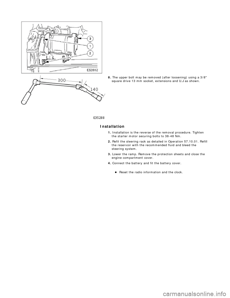
7. Remove the starter mo tor securing bolts.
1. Remove the upper securing bolt. Preferably, use a short 13 mm spanner or a Snap On Half Moon
spanner CMX1113 to initially loosen the bolt. (Refer
to the next step).
2. Remove the lower securing bolt.
3. Carefully remove the starter motor.
Page 1071 of 2490
I
nstallation
8.
The u
pper bolt may be removed (a
fter loosening) using a 3/8"
square drive 13 mm socket, ex tensions and U.J as shown.
1. Installation is the reverse of the removal procedure. Tighten
the starter motor securing bolts to 38-48 Nm.
2. Refit the steering rack as detail ed in Operation 57.10.01. Refill
the reservoir with the reco mmended fluid and bleed the
steering system.
3. Lower the ramp. Remove the protection sheets and close the
engine compartment cover.
4. Connect the battery and fit the battery cover.
R
eset the radio informat
ion and the clock.
Page 2
of 2
Page 1092 of 2490
Engine Ignition - Spark
Plugs
Re
mo
val and Installation
Remov
a
l
Installation
1.
Disc onne
ct battery ground cable (IMPORTANT, see SRO
86.15.19 for further information).
2. Remove air intake tube / meter / air cleaner cover for access;
refer to 19.10.30.
3. Remove ignition coils; refer to 18.20.41 (bank 1) and 18.20.42
(bank 2).
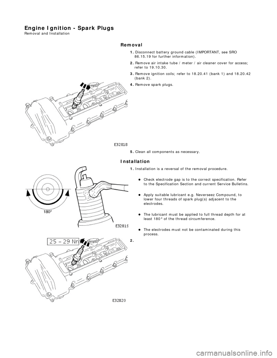
4. Re
move spark plugs.
5. Clean all components as necessary.
1. Installation
is a reversal
of the removal procedure.
Check ele
ctrode gap is to the
correct specification. Refer
to the Specification Section and current Service Bulletins.
Apply su
itable lubricant e.
g. Neverseez Compound, to
lower four threads of spark plug(s) adjacent to the
electrodes.
The lubrican t must be applied
to full thread depth for at
least 180° of the thread circumference.
T h
e electrodes must not be
contaminated during this
process.
2.
Page 1117 of 2490
I
nstallation
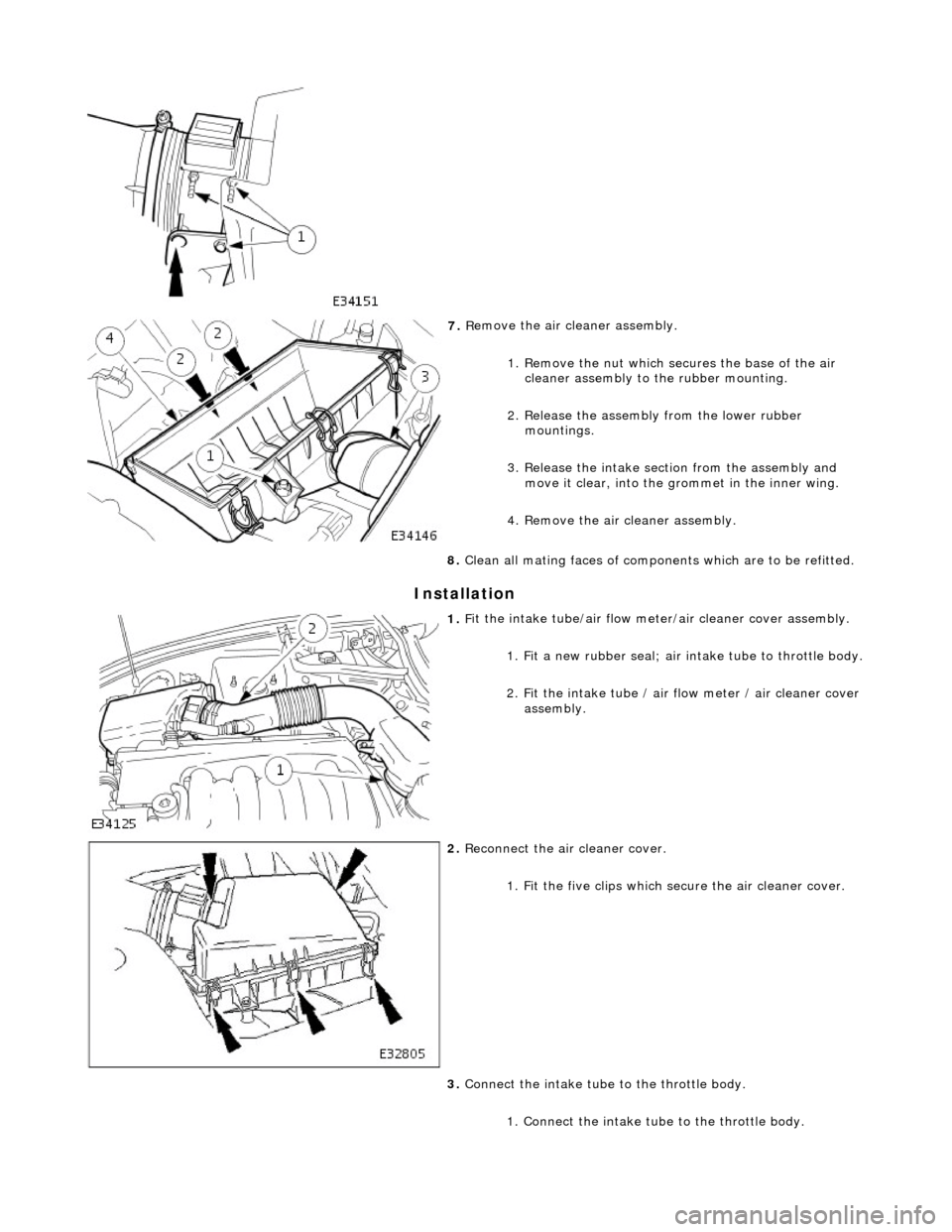
7.
R
emove the air cleaner assembly.
1. Remove the nut which se cures the base of the air
cleaner assembly to the rubber mounting.
2. Release the assembly from the lower rubber mountings.
3. Release the intake section from the assembly and move it clear, into the grommet in the inner wing.
4. Remove the air cleaner assembly.
8. Clean all mating faces of compon ents which are to be refitted.
1. F
it the intake tube/air flow meter/air cleaner cover assembly.
1. Fit a new rubber seal; air in take tube to throttle body.
2
. Fit the intake tube / air
flow meter / air cleaner cover
assembly.
2. R
econnect the air cleaner cover.
1. Fit the five clips which secure the air cleaner cover.
3. Connect the intake tube to the throttle body.
1. Connect the intake tube to the throttle body.
Page 1134 of 2490

Intake Air Distribution and Filtering - Thrott
le Body Elbow
Re
mo
val and Installation
Remov
a
l
1.
WARNING: B E
FORE PROCEEDING, IT IS ESSENTIAL THAT
WARNING NOTES GIVEN IN SECTION 100-00 (UNDER HEADING
'SAFETY PRECAUTIONS') AR E READ AND UNDERSTOOD.
Disconnect battery ground cable (IMPORTANT, see SRO
86.15.19 for further information).
2. Re
move air cleaner cover / inta
ke assembly; refer 19.10.30.
3. Remove throttle assemb ly; refer to 19.70.04.
4. Remove exhaust gas recirculation (EGR) valve where installed;
refer 17.45.01.
5. Re
lease intake elbow from right-hand support bracket.
Re
lea
se brake servo vacuum pi
pe and disconnect pipe.
1. Disconnect vacuum pipe.
2. Remove upper bolt.
6. Relea
se intake elbow from le
ft-hand support bracket.
1. Disconnect vacuum pipe.
2. Disconnect engine breather T-piece.
3. Remove upper bolt.
4. Loosen, but do not remove, lower two bolts.
7. Re
move intake elbow from supercharger.
1. Release and pull back cl ips securing bypass hoses
at charge air coolers.
2. Remove four bolts.
3. Remove hoses from charge air cooler stub pipes.
Re move as
sembly from vehicle.
4. Discard gasket.
Cle a
n all mating faces.
8. Remove by-pass valve assembly from intake elbow.
Page 1142 of 2490
Intake Air Distribution and Filtering - Throttle B
ody Elbow4.0L SC V8 -
AJ26
Re mo
val and Installation
Remova
l
1.
WARNING: BE
FORE PROCEEDING, IT IS ESSENTIAL THAT
WARNING NOTES GIVEN IN SECTION 100-00 (UNDER HEADING
'SAFETY PRECAUTIONS') AR E READ AND UNDERSTOOD.
Disconnect battery ground cable (IMPORTANT, see SRO
86.15.19 for further information).
2. Re
move air cleaner cover / inta
ke assembly; refer 19.10.30.
3. Remove throttle assemb ly; refer to 19.70.04.
4. Remove exhaust gas recirculation (EGR) valve where installed;
refer 17.45.01.
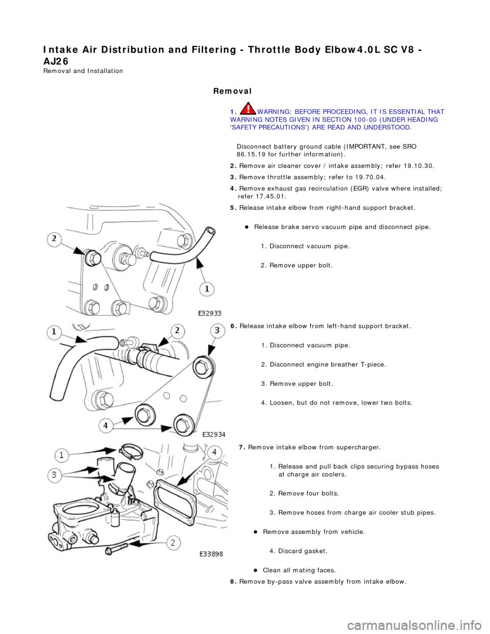
5. Re
lease intake elbow from right-hand support bracket.
Re
lea
se brake servo vacuum pi
pe and disconnect pipe.
1. Disconnect vacuum pipe.
2. Remove upper bolt.
6. Relea
se intake elbow from le
ft-hand support bracket.
1. Disconnect vacuum pipe.
2. Disconnect engine breather T-piece.
3. Remove upper bolt.
4. Loosen, but do not remove, lower two bolts.
7. Re
move intake elbow from supercharger.
1. Release and pull back cl ips securing bypass hoses
at charge air coolers.
2. Remove four bolts.
3. Remove hoses from charge air cooler stub pipes.
Re move as
sembly from vehicle.
4. Discard gasket.
Cle a
n all mating faces.
8. Remove by-pass valve assembly from intake elbow.
Page 1157 of 2490
The OR
VR system features are :
N
arrow fuel filler pipe and tank check valve.
Fue
l level vent valve (FLVV) fitted to the evaporative flan
ge and consisting of a two stage shut-off valve with rollover
protection and a pressure relief valve.
Grade ven
t valve with rollover protection, fitted to the ev
aporative flange and with an outlet pipe connected to the
FLVV vapour outlet pipe.
Large bore vapour vent pipes.
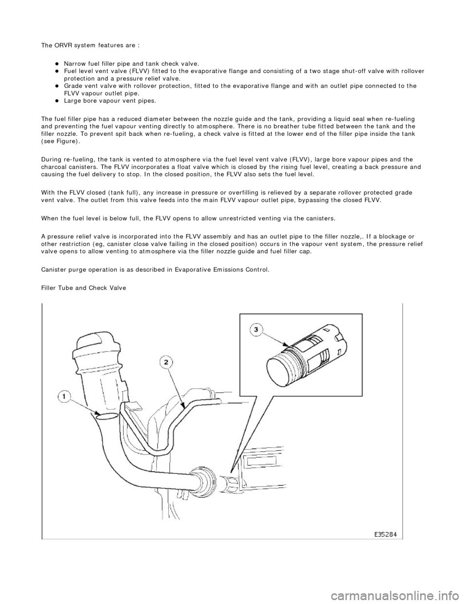
The fuel filler pipe has a reduced diameter between the nozzle guide and the tank, providing a liquid seal when re-fueling
and preventing the fuel vapour venting directly to atmosphere. There is no breather tube fitted between the tank and the
filler nozzle. To prevent spit back when re-fueling, a check valv e is fitted at the lower end of the filler pipe inside the tank
(see Figure).
During re-fueling, the tank is vented to atmosphere via the fuel level vent valv e (FLVV), large bore vapour pipes and the
charcoal canisters. The FLVV incorp orates a float valve which is closed by the rising fuel level, creating a back pressure and
causing the fuel delivery to stop. In the closed position, the FLVV also sets the fuel level.
With the FLVV closed (tank full), any increase in pressure or overfilling is relieved by a separate rollover protected grade
vent valve. The outlet from this valve feeds into the main FLVV vapour outlet pipe, bypassing the closed FLVV.
When the fuel level is below full, the FLVV opens to allow unrestricted venting via the canisters.
A pressure relief valve is incorp orated into the FLVV assembly and has an outlet pipe to the filler nozzle,. If a blockage or
other restriction (eg, canister close valve failing in the closed position) occurs in the vapour vent system, the pressure reli ef
valve opens to allow venting to atmosphere via the filler nozzle guide and fuel filler cap.
Canister purge operation is as described in Evaporative Emissions Control.
Filler Tube and Check Valve
Page 1169 of 2490
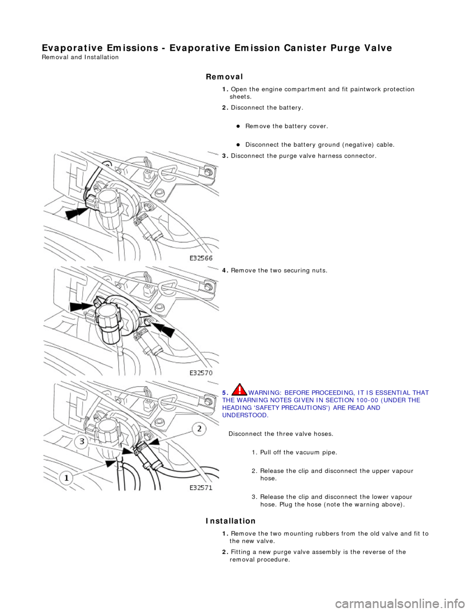
Evaporative Emissions - Evaporative Emission Canister Purg
e Valve
Re
moval and Installation
Remov
al
Installation
1. O
pen the engine compartment and fit paintwork protection
sheets.
2. Disconnect the battery.
R
emove the battery cover.
Di
sconnect the battery ground (negative) cable.
3. Di
sconnect the purge valve harness connector.
4. R
emove the two securing nuts.
5. WARNING: B
EFORE PROCEEDING, IT IS ESSENTIAL THAT
THE WARNING NOTES GIVEN IN SECTION 100-00 (UNDER THE
HEADING 'SAFETY PRECAUTIONS') ARE READ AND
UNDERSTOOD.
Disconnect the three valve hoses.
1. Pull off the vacuum pipe.
2. Release the clip and di sconnect the upper vapour
hose.
3. Release the clip and disconnect the lower vapour hose. Plug the hose (note the warning above).
1. R
emove the two mounting rubbers from the old valve and fit to
the new valve.
2. Fitting a new purge valve asse mbly is the reverse of the
removal procedure.
Page 1201 of 2490

leak
/blockage
EVAP valve failure
P0444Evaporati
ve emissions system
(EVAP) valve circuit open circuit
EVAP t
o ECM drive circuit open
circuit or high resistance
EVAP failu
re
F
or evaporative emissions pinpoint
tests,
REFER to Section 303
-1
3 Evaporative
Emiss
ions
.
P0445Evaporati
ve emissions system
(EVAP) valve circuit short circuit
E
VAP to ECM drive circuit short
circuit to ground
EVAP failu
re
F
or evaporative emissions pinpoint
tests,
REFER to Section 303
-1
3 Evaporative
Emiss
ions
.
P0447Cani
ster close valve (CCV) circuit
open circuit
CCV to ECM
drive circuit open
circuit, high resi stance or short
circuit to ground
EVAP failu
re
F
or evaporative emissions pinpoint
tests,
REFER to Section 303
-1
3 Evaporative
Emiss
ions
.
P0448Cani
ster close valve (CCV) circuit
short circuit
CCV to
ECM drive circuit short
circuit to high voltage
CCV failure
F
or evaporative emissions pinpoint
tests,
REFER to Section 303
-1
3 Evaporative
Emiss
ions
.
P0452F
uel tank pressure (FTP) sensor
circuit low voltage
FTP
sensor disconnected
FTP
sensor to ECM sense circuit
open circuit or short circuit to
ground
FTP sen
sor to ECM power supply
circuit open circuit or short circuit
to ground
F
TP sensor failure
F
or evaporative emissions pinpoint
tests,
REFER to Section 303
-1
3 Evaporative
Emiss
ions
.
P0453F
uel tank pressure (FTP) sensor
circuit high voltage
FTP
sensor to ECM signal ground
circuit open circuit
F
TP sensor to ECM wiring (supply,
sense, signal, ground) short circuit
to each other
FTP
sensor to ECM sense circuit
short circuit to high voltage
F
TP sensor failure
F
or evaporative emissions pinpoint
tests,
REFER to Section 303
-1
3 Evaporative
Emiss
ions
.
P0460Fue
l level sense signal
performance
Fue
l level sensor
to instrument
cluster circuits in termittent short or
open circuit
F
uel level sensor failure
Instrument cluster
faul
t (incorrect
fuel level data)
F
or fuel level sensor
circuit tests,
REFER to Section 303
-04
Fuel
Charging and Con
trols
.
P0506Idl
e rpm lower than expected
Ai
r intake blockage
Acce
ssory drive overload
(defective/siezed component)
Thr
ottle valve stuck closed
Throttl
e assembly failure
Chec
k the air intake system.
REFER to Section 303
-1
2 Intake Air
Distribu
tion and Filtering
.
Check t
he accessory drive
components,
REFER to Section 303
-0
5 Accessory
Dr
ive
.
F
or throttle body information,
REFER to Section 303
-04
Fuel
Charging and Con
trols
.
P0507Idle rpm
higher than expected
Inta
ke air leak between MAF
sensor and throttle
Inta
ke air leak between throttle
and engine
Engine
breather leak
Cruis
e (speed) control vacuum
failure
Thr
ottle valve stuck open
Throttl
e assembly failure
Chec
k the air intake system.
REFER to Section 303
-1
2 Intake Air
Distribu
tion and Filtering
.
Chec
k the engine breather system,
REFER to Section 303
-08
Engine
Emissi
on Control
.
F
or cruise (speed) control information,
REFER to Section 310
-03
Speed
Control.
F
or throttle body information,
REFER to Section 303
-04
Fuel
Charging and Con
trols
.
P0560Vehicle voltage
malfunction
ECM battery
power supply open
circuit, high resistance
F
or ECM power supply circuit tests,
GO to Pinpoint Test AD.
.
P0566Cruise (speed) contr
ol
CANCEL
switch ON fault
Cru
ise (speed) control switches
internal steering wheel short circuit
to ground
For cru
ise (speed) control circuit tests,
REFER to Section 310
-03
Speed